
- About Us
- Information
-

The Author ensures that the research has been conducted responsibly and ethically with adherence to all relevant regulations. read more..
- For Authors
- For Reviewer
- Manuscript Guidelines
- Membership
- Publication Ethics
-
- Journals
- Reprints
- e-Books
- Videos
- Policies
- Contact Us
 COVID-19
- Submissions


Full Text
Research & Development in Material Science
Creep and Fatigue Performance of Partial Vapor Conditioned Asphalt Binder
Mohammad Hossain1*, A S M Atiqur Rahim Khan2, Hasan Faisal3 and Rafiqul Tarefdar3
1 Department of Civil Engineering and Construction, Bradley University, USA
2 Department of Mechanical Engineering, Bradley University, USA
3 Department of Civil Engineering, The University of New Mexico, USA
*Corresponding author:Mohammad Hossain, Department of Civil Engineering and Construction, Assistant Professor, Bradley University, 1501 W Bradley Ave, Peoria, IL-61625, USA, Email: mihossain@fsmail.bradley.edu
Submission: February 13, 2018; Published: April 25, 2018

ISSN: 2576-8840 Volume5 Issue4
Abstract
Films of asphalt binders were prepared and partially vapor-conditioned in enclosed chambers at 25% Relative Humidity (RH), 49%RH, and 71%RH. Creep nanoindentation tests were performed on the partial vapor-conditioned asphalt film samples. The creep nanoindentation data were fitted using Burgers model. The Burgers model showed that the elasticity of the asphalt binder increases and viscosity decreases with the increase of RH%. Creep nanoindentation test data is used to understand fatigue performance of asphalt binder at the partial vapor conditioned situation. Finite Element Method (FEM) models are developed to examine the fatigue performance of the asphalt binder. Simulations are run using the spring and dashpot elements of Burgers model as the FEM inputs. Fatigue simulation indicates that an increase in binder viscosity would reduce permanent deformation in the asphalt binder.
Keywords: Asphalt; Creep; Fatigue; Nanoindentation; Vapor; Viscoelastic
Introduction
Moisture-induced damage in Asphalt Concrete (AC) has been studied for many years by conventional and sophisticated laboratory tests, and by using advanced numerical methods [1- 8]. Recently, researchers have shown interest on vapor-induced damage in AC since micro- and macro-scale laboratory tests can be performed on vapor conditioned test samples [8-12]. Moisture diffuses through the AC in both liquid and vapor form [8,13]. Vapor diffusion is a common scenario for AC since it is exposed to the environment. Continuous vapor diffusion occurs in the AC both at dry and moist weather condition.
A laboratory experiment was performed to determine vapor diffusion coefficient of AC samples, as well as numerical modeling, was done to show the vapor accumulation over time in the asphalt binder, aggregate, and asphalt-binder interface [8]. Later, fatigue test was done on AC samples at 100% and 0% Relative Humidity (RH) [14]. Following the footsteps, asphalt binder samples were partially vapor conditioned, and nanoindentation test was done to access the vapor-induced damage by developing a mechanical model of the asphalt binder [10,11]. One viscoelastic (i.e., Bargers model) and one viscoelasticplastic (i.e., Spring-Dashpot-Rigid or SDR model) mechanical models were developed based on the creep nanoindentation tests. However, it is unknown how partial vapor conditioning affects fatigue behavior of viscoelastic materials and what steps can be taken to reduce the damage, and that brings the motivation of the current study.
Objectives
A film of asphalt binders was prepared and partially vapor conditioned using an aqueous solution, and the mechanical model was developed to access the vapor-induced damage. The following objectives are considered for this study.
a) Develop Finite Element Method (FEM) model considering viscoelastic properties and validate FEM model with creep nanoindentation laboratory data.
b) Perform fatigue analysis on the FEM model and evaluate the fatigue performance of asphalt binder at partial vaporconditioned states.
c) Perform parametric study by changing the viscoelastic properties of the asphalt binder with a goal to reduce vaporinduced damage.
Methodology
The asphalt binder films were conditioned at 25% RH, 49% RH and 71% RH by using an aqueous solution of Potassium Acetate, Potassium Carbonate, and Sodium Chloride salts respectively. Following that, nanoindentation test on this three different RH% conditioned asphalt binder film was performed by applying creep load. The laboratory data were fitted with selected viscoelastic mechanical models such as Burgers model, and the model parameters were obtained. In the current study, Burgers model is developed in a FEM framework by using commercially available software ABAQUS. The laboratory test data are validated with the FEM model by applying a creep load on the models. After validating the FEM model, fatigue load is applied for various RH% conditions. A parametric study is done afterward to observe the fatigue behavior of the models due to changes in viscoelastic model parameters
Laboratory Tests
Partial vapor conditioning of asphalt binder
The following literature is summarized from Hossain et al. [11] and Hossain [5]. A laboratory humidity controlling chamber was developed following ASTM E104-02 standard [15]. An aqueous solution is used to create constant RH in an enclosed desiccator. Figure 1 shows an enclosed desiccator. Three salts, Potassium Acetate (CH3COOK), Potassium Carbonate (K2CO3), and Sodium Chloride (NaCl), were used to create an aqueous solution. The RH of Potassium Acetate solution varies from, 23.4% to 21.6% with a temperature range of 10 °C to 25 °C respectively. RH of Potassium Carbonate solution ranges from 43.1% to 43.2% with a temperature range of 5 °C to 25 °C respectively. RH of the Sodium Chloride solution ranges from 75.7% to 73.9% with a temperature range of 5 °C to 80 °C. The salts were mixed with distilled water in desiccators at room temperature in such a way that free water was visible after complete mixing and remain in supersaturating condition. More details on the test can be obtained from the abovementioned references.
Figure 1:

Nanoindentation test on partial vapor-conditioned asphalt binder film
Figure 2:

The following literature is summarized from Hossain et al. [11]. After partial vapor conditioning of asphalt binder, the sample was placed on the stud. The stud was fixed with glue at the bottom of a glass slide which follows vapor conditioning. The stud was put on the base of nanoindentation chamber. Figure 2 shows the nanoindentation setup for tests. A Berkovich tip was used for the tests. In some previous studies, it was observed that the Berkovich tip works better on soft asphalt binders compared to the rounded tip [16]. The loading and unloading rate was selected as 0.002mN/sec. A sitting load of 0.02mN was initially applied for each indentation. The sitting load was applied to satisfy proper contact between the binder and the nanoindenter. Load control tests were performed on binder samples, and the maximum 0.05mN load was applied for each indentation.
Ten indentations were done on each vapor-conditioned sample. In a previous study, ten indentations have been done on each phase (i.e., dispersed phase, continuous phase, and bee structure phase) of the asphalt binder for determining relaxation modulus [17]. However, in other studies, 30-40 indentations have been done on the AC mixes or mastic materials [5,18]. Mastic materials behave non-homogeneously due to the combination of fines and asphalt binder. Indentation on non-homogeneous materials such as mastic materials is challenging since the indenter can hit fines, binders, or penetrate through microvoids [19]. For this reason, the number of indentation is higher for testing non-homogeneous materials compared to homogeneous materials. Ten indentations are considered sufficient due to the homogeneous behavior of asphalt binder. The dwell time of 200 seconds was applied to observe the creep behavior of the binder [20]. The tests were done at laboratory temperature, which was set at 21 °C.
Nanoindentation Test Results
Normalized creep behavior
A normalized creep time to normalize depth plot is plotted to compare the creep behavior of the asphalt binder for different RH% conditioned states. The normalized plot provides clear differences between vapors conditioned creep data. For each conditioning state, average time and the average depth are calculated from the ten creep data. After that, the data are shifted to the origin to compare among each other. This shifted data are named as normalized data. Figure 3 shows the normalized data for three vapor conditioned states. At 200sec. of normalized creep time, the maximum normalized depth is 2282.36nm for 25%RH conditioned, 2423.72nm for 49% conditioned, and 2866.86nm for 71%RH conditioned.
Figure 3:

Viscoelastic mechanical model
Figure 4:

Several mechanical models are available to describe the viscoelastic materials using an arrangement of springs and dashpots. Springs represent the elastic effects and dashpots represent viscous effects of material. One widely used viscoelastic mechanical model is the Burgers model [21]. The Burgers model has one spring and one dashpot in series and a parallel combination of a spring and a dashpot, all of which are connected in series. Figure 4 shows the representation of the Burgers model. In the rest of the manuscript, the spring with stiffness E1 is referred as Spring-1, spring with stiffness E2 is referred as Spring-2, dashpot with dashpot coefficient η1 is referred as Dashpot-1, and dashpot with dashpot coefficient η2 is referred as Dashpot-2.
The Burgers model for the nanoindentation tests can be represented by the following Eq. (1) [22]:
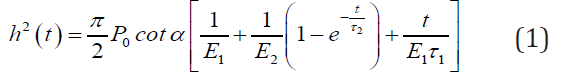
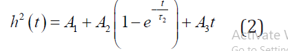
where h is the displacement due to applied load on a material, P0 is the indentation load, α includes a half angle of Berkovich indenter, E1 and E2 are the elastic moduli, t is the time, and τ 1 is the relaxation time, and τ2 is the retardation time. The dashpot coefficient can be found as η1=τ1E1 and η2=τ2E2. The total strain of the materials has three components, an instantaneous elastic strain, a viscous strain, and a retarded strain. For known values of h, P0 and t, from the indentation test, the values of E1, E2, τ1, and τ2 can be obtained from the simplified Eq. (2).
where

Burgers model parameters
The Burgers model parameters for different vapor conditioned asphalt binder are given in Table 1 [23]. Both E1 and E2 values are increased with an increase in vapor conditioning. For 71% conditioning, the E1 value is approximately 32% and 35% higher compared to the 49%RH and 25%RH respectively. For 71% conditioning, the E2 value is 49% and 54% higher compared to the 49%RH and 25%RH respectively. The relaxation time τ1 and the retardation time τ2 decreases with increase in vapor conditioning. For 71% conditioning, the τ1 is approximately 47% and 56% lower compared to the 49%RH and 25%RH respectively. For 71% conditioning, the τ2 is approximately 4% and 12% lower compared to the 49%RH and 25%RH respectively.
Table 1:Viscoelastic mechanical model parameters [23].

The results indicate that binder becomes more elastic due to vapor conditioning. An increase in elasticity in AC is usually considered a desirable effect. However, in this case, this increase in elasticity is also associated with a decrease in viscosity of the asphalt binder; which is not advantageous since this could cause de-bonding in AC materials [24].
FEM model
Burgers model is developed by using spring and dashpot elements in the ABAQUS FEM framework. Figure 5 shows the model developed in ABAQUS. The Spring-1 end is roller supported, and the Dashpot-1 end is hinged supported towards a horizontal direction. A compressive load is applied vertically to the Spring-1 end. It could be seen that Spring-2 and Dashpot-2 are overlapping and that is due to the limitation of ABAQUS visualization.
Figure 5:

FEM model verification
The creep strain of Burgers model can be calculated from Eq. (3) [21]:
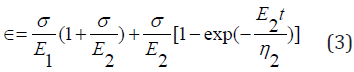
Where ⋲ is the strain, E is the modulus of elasticity and η is viscosity. The value of the parameters E and η were obtained and calculated from the laboratory test data shown in Table 1 respectively.
A creep load is applied on the FEM model, and the strain is plotted with respect to time. On the same plot the strain calculated from Eq. (3) is plotted. Figure 6 shows the time vs. strain plot for the Burgers model. From the plot, it is observed that the strain from Eq. (3) is perfectly matched to the strain found from the ABAQUS model. This is an indication that the FEM model is performing well. After this verification, fatigue analysis is carried out to determine the effect of RH% in the asphalt binder.
Figure 6:

Fatigue analysis on FEM model
A 1Hz cyclic load of magnitude 0.07mN was applied on the spring-dashpot FEM model. The spring stiffness respectively. 2500 cycles were applied on Burgers model. Figure 7 shows the Cycle vs. Strain plots for 25%RH, 49%RH and 71%RH for Burgers model. The strain shown in Figure 7 has two components; one is an elastic strain, and another is a plastic strain [25]. Elastic strain returns after the end of each cycle but the plastic strain increases with the increase of cycle numbers. It is expected that plastic strain will increase since continuous fatigue load is applied without any rest period.
In Figure 7, it is observed that plastic strain increases with increase in RH%. Though for 71% conditioning, the increase in plastic strain was lower compared to 49% and 25% RH conditioning until 1500 cycles, but it increases afterward. At 2500 cycles, the plastic strain is 1.88E-5 for 25% RH conditioning, and it is increased to 11.7% for 49% RH, and it is further rose to 38.3% for 71% RH conditioning. Also, it is observed that elastic strain is decreased with the increase of vapor conditioning since according to Table 1, Elastic Modulus is increased with increase in vapor conditioning.
Figure 7:

Parametric study of Burgers model
Plastic strain increases with increase in vapor conditioning, but it is unclear which viscoelastic material parameter (i.e., Dashpot-1 or -2) controls the shape of the strain curve for the Burgers model. Also, it is unknown how an increase in plastic strain affects asphalt binder that causes damage or permanent deformation in the AC. For this reason, a parametric study of the fatigue behavior of Burgers model is performed.
The dashpot coefficient (i.e., viscosity) which is in a series connection with a spring (denoted as Dashpot-1 in Figure 5) is increased by an increment of 15%. The fatigue analysis is run for 1000 cycles in ABAQUS. The Cycle vs. Strain curves for 25% RH with the original values and 15%, 30%, and 45% increase in Dashpot-1 coefficient are plotted in the left side of Figure 8a. It is observed that plastic strain is decreased when the Dashpot-1 coefficient is increased. After 1000 cycles and for each 15% increase in the Dashpot-1 coefficient, there is 6.9%, 11.9% and 15.9% decrease in plastic strain is observed. According to Figure 8b and for 49% RH, for each 15% increase in the Dashpot-1 coefficient, there is 7.8%, 13% and 17.4% decrease in plastic strain is observed. According to Figure 8c and for 71% RH, for each 15% increase in the Dashpot-1 coefficient, there is 9.6%, 16.8% and 22.7% decrease in plastic strain is observed.
Figure 8:

The Dashpot-1 coefficient is decreased with a decrement of 15%. The Cycle vs. Strain curves for 25 %RH with the original values and 15%, 30%, and 45% decrease in Dashpot-1 coefficient are plotted in Figure 8a. It is observed that plastic strain increases with the reduction of the Dashpot-1 coefficient. For each 15% decrease in the Dashpot-1 coefficient, there are 8.4%, 21.5% and 41.1% increase in plastic strain is observed. According to Figure 8b and for 49% RH, for each 15% decrease in Dashpot-1 coefficient, there are 9.6%, 23.5% and 44.5% increase in plastic strain is observed. According to Figure 8c and for 71% RH, for each 15% decrease in the Dashpot-1 coefficient, there are 12%, 30.4% and 58.4% increase in plastic strain is observed. From the above two parametric studies, it can be deduced that if the viscosity of asphalt binder is increased than the elastic strain remains unchanged but the plastic strain decreases. Plastic strain causes the permanent deformation in binder and AC in general.
The value of the Dashpot-2 coefficient is increased in a 15% increment similar to Dashpot-1, and the results are shown in the left side of Figure 9a. Afterward, the coefficient of Dashpot-2 is decreased similar to Dashpot-1, and the results are shown in the right side of Figure 9a. From Figure 9a it is observed that with an increase of Dashpot-2 coefficient, plastic strain decreases initially and after a certain number of cycles the slope of the Cycle vs. Strain curve starts to grow. So, increase or decrease in Dashpot-2 coefficient would not help in reducing plastic strain. Similar results are observed for 49% RH in Figure 9b and 71% RH in Figure 9c.
Figure 9:

The Spring-1 stiffness values are increased in 15% increment, and for each change, a fatigue analysis for 1000 cycles is performed in ABAQUS, and the results are shown in the left side of Figure 10a. Afterward, the Spring-1 stiffness value is decreased with a decrement of 15%, 30%, and 45% and is plotted in the right side of Figure 10a. As expected, after increasing Spring-1 stiffness, it is observed that the plastic strain remains unchanged and only elastic strain changes with the increase of Spring-1 stiffness. Similarly, after decreasing the Spring-2 stiffness, it is noted that the plastic strain remains unchanged and only elastic strain changes with a reduction in spring stiffness. From the above two parametric studies, it can be deduced that increase of Spring-1 stiffness (i.e., modulus of elasticity) results in a decrease in elastic strain. Similar results are observed for 49% RH in Figure 10b and 71% RH in Figure 10c.
Figure 10:

The Spring-2 stiffness values are increased in 15% increment, and for each change, a fatigue analysis for 1000 cycles is performed in ABAQUS, and the results are plotted in the left side of Figure 11a. Afterward, the Spring-2 stiffness value is decreased with a decrement of 15%, 30%, and 45% and is plotted in the right side of Figure 11a. After increasing Spring-2 stiffness it is observed that the plastic strain decreases with the growth of Spring-2 stiffness. For each 15% increase in Spring-2 stiffness, there are 6.5%, 11.4%, and 15.3% decrease in plastic strain are observed. On the other hand, after decreasing the Spring-2 stiffness, it is noted that the plastic strain increases with the reduction of spring stiffness. For each 15% decrease in stiffness, there are 7.4%, 18.7%, and 33.6% increase in plastic strain are observed. From the above two parametric studies, it can be deduced that increase of Spring-2 stiffness (i.e., modulus of elasticity) results in a decrease in plastic strain. It should be noted that Spring-2 and Dashpot-2 are in parallel and for this reason increase in Spring-2 value improves the retarded strain and that reduces the plastic strain in the asphalt binder.
According to Figure 11b and for 49% RH, for each 15% increase in Spring-2 stiffness, there are 6.1%, 10.4%, and 14.1% decrease in plastic strain is observed. On the other hand, after decreasing the Spring-2 stiffness, it is noted that the plastic strain increases with the decrease of spring stiffness. For each 15% decrease in stiffness, there are 7%, 17.4%, and 31.3% increase in plastic strain are observed. According to Figure 11c and for 71% RH, for each 15% increase in Spring-2 stiffness, there are 4%, 6.4%, and 8.8% decrease in plastic strain is observed. On the other hand, after decreasing the Spring-2 stiffness, it is noted that the plastic strain increases with the decrease of spring stiffness. For each 15% decrease in stiffness, there are 4%, 10.4%, and 19.2% increase in plastic strain are observed.
Figure 11:

Discussion
The asphalt binder films were vapor conditioned at 25%RH, 49%RH and 71%RH by using an aqueous solution of Potassium Acetate, Potassium Carbonate, and Sodium Chloride salts respectively. Following that, nanoindentation test on this three different RH% conditioned asphalt binder film was performed by applying creep load. The laboratory data were fitted with selected viscoelastic mechanical models such as Burgers model, and the model parameters were obtained. In the current study, Burgers model is developed in a FEM framework by using commercially available software ABAQUS. The laboratory test data are validated with the FEM model by applying a creep load on the models. After validating the FEM model, fatigue load is applied for various RH% conditions. A parametric study is done afterward to observe the fatigue behavior of the models due to changes in viscoelastic model parameters.
It is noted that with an increase of vapor conditioning elastic strain decreases but plastic strain increases. The plastic strain that causes permanent deformation and damage in asphalt binder or AC, in general, is affected by vapor conditioning. The increase of vapor conditioning thus results in early damage and failure. From the parametric study, it is observed that if the viscosity of the material is increased, then the plastic deformation is decreased in the asphalt binder. Also, the increase of elasticity in the asphalt binder could decrease the plastic deformation. Thus, it is preferable to have an AC material that has higher viscoelastic properties. This study will help to engineer new asphalt binder or improve current antistripping materials that use to reduce vapor- or moisture-induced damage in AC. However, more research is needed to draw a definite conclusion on reducing moisture- or vapor-induced damage in AC.
Acknowledgment
The current research is funded by the Center for Teaching Excellence and Learning (CTEL) and Office of Sponsored Programs (OSP) at the Bradley University. The nanoindentation laboratory tests were done at the University of New Mexico.
References
- Caro S, Masad E, Bhasin A, Little D (2010) Coupled micromechanical model of moisture-induced damage in asphalt mixtures. J Mater Civ Eng ASCE 22: 380-389.
- Copeland AR (2007) Influence of moisture on bond strength of asphaltaggregate systems. Vanderbilt University, USA.
- Hefer AW (2004) Adhesion in bitumen-aggregate systems and quantification of the effects of water on the adhesive bond. Texas A&M University, USA.
- Hossain MI, Tarefder RA (2014) Quantifying moisture damage at mastic– aggregate interface. Int J Pavement Eng 15: 174-189.
- Hossain MI (2013) Modeling moisture-induced damage in asphalt concrete. The University of New Mexico, USA.
- Kringos N, Scarpas T, Kasbergen C, Selvadurai P (2008) Modelling of combined physical-mechanical moisture-induced damage in asphaltic mixes, part 1: governing processes and formulations. Int J Pavement Eng 9(2): 115-128.
- Kringos N, Scarpas A, Copeland A, Youtcheff J (2008) Modeling of combined physical-mechanical moisture induced damage in asphaltic mixes, Part 2: moisture susceptibility parameters. Int J Pavement Eng 9(2): 129-151.
- Arambula E, Caro S, Masad E (2010) Experimental measurement and numerical simulation of water vapour diffusion through asphalt pavement materials. J Mater Civ Eng ASCE 22(6): 588-598.
- Barlas G (2013) Materials characteristics of hot mix asphalt and binder using freeze-thaw conditioning, The University of New Mexico, USA.
- Faisal HM, Hossain MI, Tarefder RA (2015) Nanomechanical evaluation of vapor-conditioned and unconditioned asphalt. Transp Res Rec J Transp Res Board 2506: 126-136.
- Hossain MI, Faisal HM, Tarefder RA (2015) Characterisation and modelling of vapour-conditioned asphalt binders using nanoindentation. Int J Pavement Eng 16(5): 382-396.
- Hossain MI, Tarefder RA (2015) Behavior of asphalt mastic films under laboratory controlled humidity conditions. Constr Build Mater 78: 8-17.
- Spinel SC (2009) A coupled micromechanical model of moistureinduced damage in asphalt mixture: formulation and applications, Texas A&M University, USA.
- Tong Y, Luo R, Lytton RL (2013) Modeling water vapor diffusion in pavement and its influence on fatigue crack growth of fine aggregate mixture. Transp Res Rec J Transp Res Board 2373: 71-80.
- ASTM Designation No E104-02 (2012) Standard practice for maintaining constant relative humidity by means of aqueous solutions.
- Gopalakrishnan K, Birgisson B, Taylor P (2011) Nano-technology in civil infrastructure: a paradigm shift. Springer, Berlin, Germany.
- Allen RG, Little DN, Bhasin A, Lytton RL (2013) Identification of the composite relaxation modulus of asphalt binder using AFM nanoindentation. J Mater Civ Eng ASCE 25: 530-539.
- Khorasani S, Masad E, Kassem E, Abu Al-Rub RK (2013) Nano-mechanical characterization of mastic, aggregate, and interfacial zone in asphalt composites. J Test Eval 41: 1-9.
- Hossain M, Faisal H, Tarefder R (2014) Viscoelastic behavior of mastic phase of asphalt concrete. In: Kim RY (Ed.), 12th Int Soc Asph Pavements Conf Asph Pavement, Taylor & Francis Group, London, Raleigh, North Carolina, USA, pp. 1375-1384.
- Tarefder RA, Faisal H (2013) Effects of dwell time and loading rate on the nanoindentation behavior of asphaltic materials. J Nanomechanics Micromechanics ASCE 3: 17-23.
- Huang YH (2004) Pavement analysis and design, (2nd edn), Pearson Prentice Hall, Upper Saddle River, NJ, USA.
- Fischer-Cripps AC (2004) A simple phenomenological approach to nanoindentation creep. Mater Sci Eng A 385: 74-82.
- Hossain M, Khan ASMAR, Faisal H, Tarefder R (2015) Finite element and mechanical modeling of fatigue behavior of partial vapor-conditioned viscoelastic material. Proc ASME Int Eng Congr Expo, Micro- Nano- System Eng Packag, ASME 10: V010T13A010-1-10.
- Hossain MI, Tarefder RA (2014) Determining normal and shear pull-off strength of asphalt mastic films due to diffusion of water vapour. Transp Res Board 93rd Annu Meet, Transportation Research Board, Washington DC, USA.
- Richard Kim Y (2009) Modeling of asphalt concrete. ASCE Press and McGraw-Hill, USA.
© 2018 Mohammad Hossain . This is an open access article distributed under the terms of the Creative Commons Attribution License , which permits unrestricted use, distribution, and build upon your work non-commercially.
Editor In Chief


.jpg)


Signup for Newsletter

Quick Links
 Editorial Board Registrations
 Submit your Article
 Refer a Friend
 Advertise With Us
Our Recent Edition

.jpg)


Top Editors


.jpg)


.bmp)
.jpg)
.png)
.jpg)


.jpg)


.png)

.png)


.png)


Financial Support

Sponsors

Latest e-Books

Latest Video

 a Creative Commons Attribution 4.0 International License. Based on a work at www.crimsonpublishers.com.
Best viewed in
a Creative Commons Attribution 4.0 International License. Based on a work at www.crimsonpublishers.com.
Best viewed in