- Submissions

Full Text
Polymer Science: Peer Review Journal
The Investigation of Damage Mechanisms of Thermally Aged 4/3 Glare with Cone Beam Computed Tomography
Hamdi Fidan1, Mustafa Özgür Bora2*, Onur Çoban2 and Eyüp Akagündüz3
1Turkish Airlines Technic Inc, Turkey
2Kocaeli University, Faculty of Aeronautics and Astronautics, Turkey
3TUBITAK-MAM, Materials Institute, Turkey
*Corresponding author: Mustafa Özgür Bora, Kocaeli University, Faculty of Aeronautics and Astronautics, 41285, Kocaeli, Turkey
Submission: March 30, 2021;Published: June 03, 2021
ISSN: 2770-6613 Volume2 Issue1
Abstract
In this paper, the effect of thermal cycles on the flexural properties of 4/3 configured Glass Reinforced Aluminum (GLARE) has been evaluated with Cone Beam Computed Tomography (CBCT). GLARE is manufactured by Turkish Airlines Technic Inc. composite workshop with autoclave method. After manufacturing process, GLARE samples are subjected to thermal cycles (0, 25, 50, 100, 200 and 300 cycles) in a full function climatic chamber at temperature ranges -30 °C to +40 °C for 120min. Threepoint bending tests are applied to thermally aged GLARE samples by using Zwick Z-250 universal test machine. The variation on the flexural modulus and strength values of GLARE samples is determined. From test results, the decrements of the flexural strength and modulus of GLARE samples are occurred for 300 thermal cycles as 4.95% and 4.85%, respectively. From CBCT observations, it is determined that delamination and metallic layer fractures are the main damage mechanisms.
Keywords: Ageing; Composites; Damage zone; Mechanical properties; Nondestructive technique
Abbreviations: CBCT: Cone Beam Computed Tomography; FMLs: Fiber Metal Laminates; NDT: Non- Destructive Testing; SRM: Structure Repair Manuel; GLARE: Glass Reinforced
Introduction
Structural weight of an aircraft has an extreme importance on fuel consumption, transport capacity and flight performance due to the ratio (maximum payload)/(maximum take-off weight). High design stress levels have to be adopted for achieving weight savings for aircraft structural parts. By this way, materials which have a high specific property are required. The design of a modern aircraft fuselage structure demands more refined techniques and improved materials [1]. Fiber Metal Laminates (FMLs) have unique characteristics such as manufacturing flexibility (metallic layer and composite layer configurations), material selections (aluminum alloy, magnesium alloy, titanium alloy, carbon fiber, glass fiber or aramid fiber), bearing strength, high impact resistance, low density according to the conventional metals, lightening resistance, corrosion free due to glass fiber reinforced epoxy composites. Due to these unique properties, FMLs are promising as performance materials for aircraft structural parts such as fuselage and wing skin panels [2]. By using FMLs, both production costs and operating costs reduce. In the entire top half of the A3XX fuselage around the passenger cabin, FMLs are used to achieve this cost reduction and to increase the safety level. FMLs also use cargo floor panels, liners, bulkheads, flap skin panels and stabilizers leading edge panels [3,4]. Typically these structural panels have a thickness of 2-5mm. Aluminum alloys (2024-T3 and 7475-T76) and each prepreg (glass, carbon or aramid based) layers are generally used with a thin thickness (0.2 to 0.5mm) and 0.125mm, respectively. The volume fraction of metallic layers is nearly about 50-60%, depending on the number of prepreg layers employed that is generally 2, 3 or 4 [4].
JAR 25.603 requires one to “take into account the effects of environmental conditions, such as temperature and humidity, expected in service.” The Glass Reinforced Aluminum (GLARE) includes two materials with different thermal expansion coefficients, i.e. aluminum and glass fibres. Since the GLARE will be cured at 120 °C and operated in a temperature range between approximately −50 °C and +70 °C, temperature related effects have to be taken into account [5]. During flight time period, structural parts of an aircraft can be subject to thousands of such thermal cycles. Due to these environmental effects, damages can be occurred, especially at the interface region of metal/composite, due to differences up to 80% in coefficient of thermal expansion of the metallic layers and composite layers [2]. Graafmans [6] investigated the delamination behaviour of GLARE edges by using time consuming cycling tests. Results showed that the shear stresses between aluminum layer and glass fibres were decreased due to the resin plasticizing effect. By this way, environment-related delamination occurred [6]. From literature surveys on FMLs, there is not easily found an article which is subjected to thermal cycling. The information probably exists, as it is used on aircrafts that are submitted to a rigorous certification process to guarantee that they operate under safe conditions. However, this information may be restricted by confidentiality agreements [2]. The increasing demand, from the engineering viewpoint, for using advanced composite materials in critical load bearing components in a variety of structures under different loading modes, requires great efforts in various research areas such as development of reliable methodologies for life prediction, characterization of damage evolution and elucidation of fracture micro-mechanisms. These complicated issues are still long term goals, however, in recent years intense activity has been devoted. Non-Destructive Testing (NDT) techniques were used for the characterization of damage progress and micro-mechanisms of failures in composite materials [7]. NDT techniques allowed to understand the evolution of material degradation under mechanical loads and to anticipate the delamination’s or buckling. NDT and evaluation of FML is still a challenge, especially considering that large structures are typically sought (e.g., aircraft fuselage) [8]. From literature survey, researchers investigated the damage mechanisms which were occurred in the FML materials due to the applied loads with NDT techniques such as acoustic emission [9], flying laser spot thermography technique [10] and active thermography technique [8]. For determining and tracking the damage mechanisms which were occurred in the composite materials due to mechanical loads, these NDT techniques had been lacked micrometer resolution. What is desirable is an NDT technique that offers high resolution to evaluate the internal damage mechanisms with 3D, without the issues of destroying the composite sample or introducing new damage. Cone Beam Computed Tomography (CBCT) can successfully determine the internal damage mechanisms at voxel resolutions in the order of 100mm and above. Reconstructing interior structural details with a high resolution on a scale of interest for damage evaluation is possible by using CBCT [11]. However, the use of CBCT technique for studying bending damage in FML materials has not been reported.
First of all, 4/3 configured GLARE was manufactured by Turkish Airlines Technic Inc. composite workshop with autoclave method according to the Structure Repair Manuel (SRM) of Boeing 737-800. After manufacturing process, GLARE materials were subjected to the thermal cycles (0, 25, 50, 100, 200 and 300) in a full function climatic chamber according to typical A Check interval for commercial aircraft maintenance programs. Three point bending tests were applied to determine the variation of flexural properties such as flexural modulus and flexural strength of various thermal cycled GLARE materials. At last, for identifying the internal flexural damage mechanisms of 4/3 configured GLARE materials, CBCT technique was used.
Materials and Methods
Materials and manufacturing technique
Figure 1:Autoclave method process steps for manufacturing 4/3 configured GLARE [12].
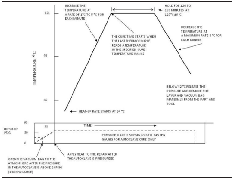
GLARE material with the configuration 4/3 (four layer of AA2024-T3 aluminum sheets and three layer of BMS 8-79 Style 120 38” CL3 prepreg) manufactured at Turkish Airlines Technic Inc. composite workshop by using autoclave method according to the Structure Repair Manuel (SRM) of Boeing 737-800. BMS 8-79 Style 120 38” CL3 is a fiberglass pre-preg style that contains HexPly® F155 resin system. It is an advanced modified epoxy formulation designed for autoclave curing to offer very high laminate strengths, coupled with increased fracture toughness and adhesive properties. A vacuum bag was prepared over the GLARE material and the set was cured at 121±5 °C for 180min under an autoclave pressure of 345kPa (50psi). The heat-up rate started at 54 °C as the autoclave pressure reached the programmed value, and as the temperature reached 52 °C the pressure released and removed the layup and vacuum bag materials from the part and tool to prevent excessive resin bubbling at the edges of the plate. Figure 1 shows the autoclave method process steps used in this work according to [12]. Adequate temperature levels to be used during the consolidation process can be determined by using Boeing 737-800 Structural Repair Manual 51-70-05. The manufactured GLARE sample has a thickness of 3.2mm and the dimensions of 550mmx550mm.
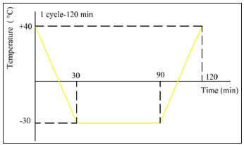
Thermal aging condition and three point bending tests After manufacturing, GLARE samples were carefully lasermachined in the form of test coupons for three point bending tests according to ASTM D790-15. Dimensions of the GLARE sample test coupons and the configuration of GLARE sample are depicted in Figure 2. For accelerated thermal aging process, Atlas SC 600 Solar Simulator climatic chamber was used. GLARE samples are subjected to the thermal cycles (0, 25, 50, 100, 200 and 300 cycles) in a full function climatic chamber at a temperature ranges -30 °C to +40 °C for 120min. 300 thermal cycles corresponds to typical A Check interval for commercial aircraft maintenance programs. Samples were subjected to cyclic environments with the following controlled factors: the Relative Humidity (RH) and the surrounding temperature (T). After thermal aging, GLARE samples were removed from the climatic chamber. Figure 3 illustrates the applied temperature changes during the thermal cycling tests. From Figure 3, one cycle of thermal aging process was 120min according to a flight of an aircraft which was serviced from Venice to Istanbul [13]. In addition, RH was only applied between 0° and +40 °C. Accelerated thermal aging cycles imposed on GLARE samples at a temperature range of -30 to +40 °C with 98% RH. After thermal aging at climatic chamber, three point bending tests were applied to GLARE samples. Support span of 16 times the depth of the GLARE samples was used for three point bending tests. Rigid rollers which were used for loading and supporting devices had a diameter of 12mm. In addition, for preventing the local core damage at the face skin of the GLARE samples rubber pressure pads which had a width of 12mm were used. At least five samples of GLARE were tested under 10min/min flexural strain rates and flexural load/strain values were recorded using Zwick Z-250 universal test machine. Average values were given. The variation of flexural properties such as flexural modulus and flexural strength of GLARE samples was determined.
Figure 2:Three point bending test coupon of GLARE sample and the configuration of GLARE sample.

Figure 3:The temperature variations imposed during the accelerated thermal cycling test of GLARE samples.
Cone Beam Computed Tomography (CBCT) scanning
GLARE samples were scanned with Newtom Vgi-CBCT system after three point bending tests. NewTom Vgi-CBCT introduces a new image chain consisting of elements that boost standard CBCT performance. CBCT scanning process schematic and scanning parameters of GLARE samples are given in Figure 4 [11] and (Table 1), respectively. A series of divergent X-rays were used to determine the internal damage mechanisms in the GLARE samples in CBCT technique. A motorized turntable fitted between the X-ray source and the planar detector. During scanning process, GLARE samples fixed above the turntable and a rotational movement applied to sample by means of angular steps. As a result of the acquisition of 2D projections throughout this rotation, only one rotation or less is needed to acquire a 3D dataset. Typically, a few hundreds of projections are collected. 2D image slices received by the planar detector are used by computer for image processing. Various algorithms can be used for reconstruction of 2D (surface) or 3D (volumetric) sample images. This process is called rendering. At the last step of process, damage zones can be visualized by means of surfaces (multi-planar) or volumetric [14].
Table 1:

Figure 4: Schematic representation of CBCT scanning process [11].

Results and Discussion
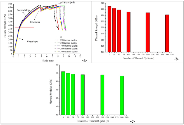
The effect of thermal aging cycle on the flexural properties of GLARE samples is presented in Figure 5. Flexural strength is the maximum stress which is calculated by using Eq. 1 [15].

Where; σ=stress in the outer fibers at midpoint, MPa, P=load at a given point on the load-deflection curve, N, L=support span, mm, b=width of beam tested, mm and d=depth of beam tested, mm. From Figure 5b, the flexural strength is obtained on qualification three point bending tests are of the order of 687MPa. After exposing the GLARE samples for thermal cycles of 300 (600h), the flexural strength values decrease about 4.95% (653MPa). It is clearly said that the variation of the number of thermal cycle has been caused for a change on the flexural strength of GLARE samples. The flexural strength/strain behavior of thermally aged GLARE samples with various cycles is very similar, highlighting the strong influence of the aluminum in these samples as similar to [16]. It is expected that any degradation of the GLARE samples, if present, would be restricted to the thermal expansion mismatch between the metallic layer and the polymeric composite ply [2]. It has been reported that such thermal cycling applied to multi layered fiber reinforced polymers would result in damages similar to a mechanical fatigue process [17]. From flexural strength/strain curves (Figure 5a), dual slope curve are obtained for all the tested samples. In the first slope, flexural load and strain maintain an approximate linear relationship, as deformation of fiber layers and aluminum alloy layers are both elastic. The coordinate deformation between layers and interface contributes to ensure the structural integrity of GLARE samples. For second slope, 2024-T3 material begins to yield with the increased deflection while the composite layers still remains elastic due to its feature of linear elasticity. Thus the tangent slope in second slope is clearly lower compared with that of the initial straight-line portion of the flexural load-strain profile as similar to [18]. Good repeatability is also another characteristic of the three point bending tests, irrespective to the various numbers of thermal cycles. Beside this, the GLARE samples have not failed after reaching the first peak load (Figure 5a). The emergence of fluctuating downward after the first peak load is a consequence of complex failure, which includes fiber breakage and delamination between metallic layer and composite layer. Hence, the support span/GLARE sample thickness ratio value within a range from 14 to 24 is the necessary condition for effective flexural failure of GLARE samples [18]. Flexural modulus is defined as a tendency of material to bend and determined from the slope of stress-strain curve. Flexural modulus also can be calculated using Eq. 2 [15,19];

Where; EB=modulus of elasticity in bending, MPa, L=support span, mm, b=width of beam tested, mm, d=depth of beam tested, mm, and m=slope of the tangent to the initial straight-line portion of the load-deflection curve, N/mm of deflection. From Figure 5c, similar to the change of the flexural strength values it is determined that the flexural modulus values decrease with the increment of number of thermal cycles. The flexural modulus values decrease approximately 4.85% for 300 thermal cycles according to unaged GLARE samples.
Figure 5: a. Flexural strength/strain curves of various thermally aged GLARE samples, b. The variation of flexural strength values according to number of thermal cycles, c. The variation of flexural modulus values according to number of thermal cycles.
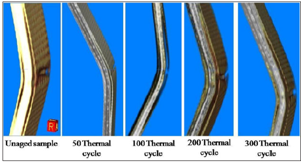
The cross sectional images and 3D images of various thermally aged GLARE samples are obtained by using CBCT technique (Figures 6 & 7). A scattering of X-rays can occur at interfaces between metallic layers and composite layers. The shining boundary in the image can be considered due to the partial scattering of X-rays at the interface [20]. As a result, black regions with a boundary between the metallic layer (white regions) and composite layer (grey regions) are deemed to represent a set of delamination. It is clear that the delamination appears all of the GLARE samples. Beside this, delamination is extended through between the both rear and upper face layers of 2024-T3 and composite plies as similar to [21]. The length of the delamination increases with the number of thermal cycles. For unaged GLARE sample, the length of the delamination 12.2mm and 11.2mm from the midpoint of the material. In addition, these values increase totally 1.1mm. It is investigated that both flexural strength and modulus values decrease due to this increment which is about the length of the delamination. Another important investigation is that the bending angles between the legs of the GLARE samples decreases with the increment of the number of thermal cycles. V-shaped geometry occurs for the entire of the GLARE samples after three point bending tests. Angles between the legs of V-geometry shapes are measured from the 3D tomograms and 154.3° for unaged GLARE sample and 141.1° for 300 thermal cycles. This result implies that higher thermal cycles affect the flexural properties of the GLARE sample. From 3D views of the GLARE samples, it is easily determined that damage areas are extended through both axial and longitudinal directions (Figure 7). On the other hand, the metallic layer which is placed at the rear face side of the material also fractures through the axial direction for all the GLARE samples. This damage mechanism (fracture of the 2024-T3 layer) occurs at the failure peak load of the flexural loadstrain curves.
Figure 6:Typical cross-sectional images of GLARE samples obtained from CBCT.
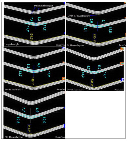
Figure 7:3D images of GLARE samples obtained from CBCT.
Conclusion
Flexural properties and damage mechanisms of 4/3 GLARE materials were investigated after the thermal aging with various number of cycles. From the obtained results, the following conclusions can be drawn: Flexural strength that was obtained on qualification three point bending tests is of the order of 687MPa. After exposing the GLARE samples to thermal aging with 300 cycles (600h), the flexural strength values decrease about 4.95% (653MPa). Beside this, the flexural modulus values decrease with the increment of number of thermal cycles. The flexural modulus values decrease approximately 4.85% for 300 thermal cycles according to unaged GLARE samples. The delamination and metallic layer fractures were clearly identified in the CBCT sectional view and 3D images, and the propagation of delamination and the bending angle values were determined. The length of the delamination values was increased nearly 1.1mm for 300 thermal cycles according to undamaged GLARE samples. In addition, the bending angle of the 300 thermal cycled GLARE sample was calculated as 141.1°. This result implies that higher thermal cycles affect the flexural properties of the GLARE sample. From 3D views of the GLARE samples, damage areas are extended through both axial and longitudinal directions.
References
- Asundi A, Choi AYN (1997) Fiber metal laminates: An advanced material for future aircraft. Journal of Materials Processing Technology 63(1-3): 384-394.
- da Costa AA, da Silva DFNR, Travessa DN, Botelho EC (2012) The effect of thermal cycles on the mechanical properties of fiber-metal laminates. Materials and Design 42: 434-440.
- Vlot A, Vogelesang LB, de Vries TJ (1999) Towards application of fibre metal laminates in large aircraft. Aircraft Engineering and Aerospace Technology 71(6): 558-570.
- Vlot A (2001) Glare: history of the development of a new aircraft material. Kluwer Academic Publishers, Netherlands.
- Vermeeren CAJR, Beumler TH, DE Kanter JLDG, Van Der Jagt OC, Out BCL (2003) Glare design aspects and philosophies. Applied Composite Materials 10: 257-276.
- Graafmans G (1995) Thermal behaviour of fibre metal laminates. Delft University of Technology, Netherlands.
- Bussiba A, Kupiec M, Ifergane S, Piat R, Böhlke T (2008) Damage evolution and fracture events sequence in various composites by acoustic emission technique. Composites Science and Technology 68(5): 1144-1155.
- Ibarra Castanedo C, Avdelidis NP, Grinzato EG, Bison PG, Marinetti S, et al. (2011) Delamination detection and impact damage assessment of GLARE by active thermography. International Journal of Materials and Product Technology 41(1-4): 5-16.
- Woo SC, Choi NS (2006) Analysis of dominant frequencies of glass-fiber/aluminum laminates during acoustic emission measurement. Key Engineering Materials 321-323: 901-906.
- Montinaro N, Cerniglia D, Pitarresi G (2017) Flying laser spot thermography technique for the NDE of fibre metal laminates disbonds. Composite Structures 171: 63-76.
- Fidan S, Bora MÖ, Çoban O, Tuna V (2016) Damage characterization of repeatedly impacted glass fiber reinforced polyester-armor steel composites with cone beam computed tomography technique. Polymer Composites 37(2): 583-593.
- (2012) Boeing 737-800 Structural Repair Manual, Chapter 51, Structures-General, US.
- https://www.flightradar24.com/data/aircraft/tc-jst#f81e26a
- Akatay A, Bora MÖ, Fidan S, Çoban O (2015) Damage characterization of three point bended honeycomb sandwich structures under different temperatures with cone beam computed tomography technique. Composite Structures 39(1): 46-54.
- (2016) ASTM D790-15, Standard test methods for flexural properties of unreinforced and reinforced plastics and electrical insulating materials.
- Carrillo JG, Cantwell WJ (2009) Mechanical properties of a novel fiber-metal laminate based on a polypropylene composite. Mechanics of Materials 41(7): 828-838.
- Henaff Gardin C, Lafarie Frenot MC (2002) Specificity of matrix cracking development in CFRP laminates under mechanical or thermal loadings. International Journal of Fatigue 24(2-4): 171-177.
- Li H, Xu Y, Hua X, Liu C, Tao J (2018) Bending failure mechanism and flexural properties of GLARE laminates with different stacking sequences. Composite Structures 187: 354-363.
- Nurhaniza M, Ariffin MKAM, Mustapha F, Baharudin BTHT (2015) Flexural analysis of aluminum/carbon-epoxy fiber metal laminates. Australian Journal of Basic and Applied Sciences 9(19): 35-39.
- Na W, Kwon D, Yu WR (2018) X-ray computed tomography observation of multiple fiber fracture in unidirectional CFRP under tensile loading. Composite Structures 188: 39-47.
- Rajkumar GR, Krishna M, Narasimhamurthy HN, Keshavamurthy YC, Nataraj JR (2014) Investigation of tensile and bending behavior of aluminum based hybrid fiber metal laminates. Procedia Materials Science 5: 60-68.
© 2021 Mustafa Özgür Bora. This is an open access article distributed under the terms of the Creative Commons Attribution License , which permits unrestricted use, distribution, and build upon your work non-commercially.
 a Creative Commons Attribution 4.0 International License. Based on a work at www.crimsonpublishers.com.
Best viewed in


.jpg)


 Editorial Board Registrations
 Submit your Article
 Refer a Friend
 Advertise With Us
.jpg)


.jpg)


.bmp)
.jpg)
.png)
.jpg)


.jpg)


.png)

.png)


.png)


