
- About Us
- Information
-

The Author ensures that the research has been conducted responsibly and ethically with adherence to all relevant regulations. read more..
- For Authors
- For Reviewer
- Manuscript Guidelines
- Membership
- Publication Ethics
-
- Journals
- Reprints
- e-Books
- Videos
- Policies
- Contact Us
 COVID-19
- Submissions


Full Text
Progress in Petrochemical Science
Modeling of Chemical Reacting Transport Phenomena in a PEM Fuel Cell using Finite Volume Method
Mohammed Jourdani*, Hamid Mounir and Abdellatif El Marjani
Department of Mechanical Engineering, Mohamed V University, Morocco
*Corresponding author: Mohammed Jourdani, Department of Mechanical Engineering, Mohamed V University, Morocco, North Africa
Submission: April 11, 2018;Published: September 19, 2018

ISSN 2637-8035Volume2 Issue5
Abstract
Modeling the transport phenomena in a fuel cell system is important to the development of fuel cells. Numerical models can be used to improve some important areas in PEMFCs design, such as water management, fuel cell thermal management, fuel cell stack design, and fuel delivery. The purpose of this work is to present a two-dimensional transient model of the gas flow in the fuel cell (PEMFC). The model includes various conservation equations such movement and energy equations. The governing equations were resolved by the finite volume method.
Keywords: Water; Modeling; Degradation; Performance; Finite volume method; PEMFC
Introduction
PEFC is a device that converts chemical energy in fuels directly into electricity with high efficiency, no combustion or moving parts [1]. PEMFC has many advantages, including clean, efficient and high-power density, etc., and it is regarded as an ideal power source for vehicles in the future [2,3]. Water management is one of the critical issues in the performance modeling of a PEMFC. At high cell current densities, excessive water transport throughout the membrane and water production in the cathode catalyst layer result in mass transport limitations and flooded GDL gas pores with water. At low cell current densities membrane dehydration may occurs at the anode side resulting in membrane ohmic losses. These losses cause reduction of the PEMFC performance. Modeling the transport phenomena in a fuel cell system is important to the development of fuel cells. Numerical models can be used to improve some important areas in PEMFCs design, such as water management, fuel cell thermal management, fuel cell stack design, and fuel delivery.
Problem Description
The computational domain is depicted in Figure 1. The model consists of gas channel, gas diffusion layer, cathode catalyst layer. The interfaces between the GDL and membrane are impregnated with a platinum catalyst and are called catalyst layer (CL).
Figure 1:Structure of the diffusion layer.

Mathematical Modeling
Assumptions
In our model, the following assumptions are used
A. Stationery model
B. The temperature of the cell is constant
C. The gas flow is laminar and incompressible
D. Viscosity of the mixing gas is constant
E. Isotropic and homogeneous electrodes
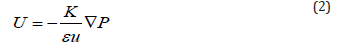
F. The momentum equations will be reduced Darcy equations
G. The water in the cathode is a vapor
H. Two-dimensional mathematical model
Governing equations
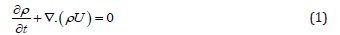
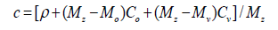
Mixing speed U is expired as a function of the concentration of mixture C using ideal gas law (P = CRT), and the concentration is expired as a function of the density ρ of the mixture, the concentrations of oxygen and water vapor CO and CV, and the molar masses of species (O2,H2O,N2)
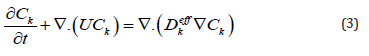
DeffD Effective diffusion coefficients are obtained using Bruggeman correlation and their dependencies of temperature and pressure [4]
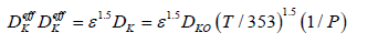
K,μ,ε,DK0 respectively are permeability, viscosity, medium porosity and species diffusion coefficients under standard conditions.
Boundary conditions
The unknown is ρ,CO2,CH2O, so the external borders of the field calculation (Figure 2) zero flow condition is used except for the air inlet and the catalyst layer.
Figure 2:Field Calculation.

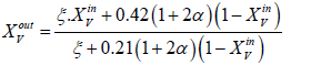
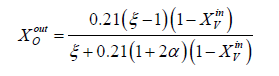
a. y=0 at the air inlet, we take the average values in the air channel
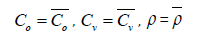
To calculate the average values
Between the input and the output of the channel, we need the expression of mole fractions of species to the outputs which are written [5]
b. y=0 on the surface of the collector plate of the current, this segment is a non-permeable boundary
(wall) applying conditions of zero flow and speeds:
c. x=0 and x=W are the axis passing through the half of the channels of the opening’s gases, which
are axes of symmetry where the condition of symmetry is applied.
d. y=H It is on the border with the catalyst layer where it is assumed that the electrochemical reaction is going to a fast, so concentrations are negligible downstream of the layer and the diffusive flux Jk species are depending on the density I which varies according to the distance x according to the curve in Figure 3 given by BAO and others [5] which can be interpolated by a polynomial.
Figure 3:Current density curve.

Numerical Procedure
The governing equations are discretized by using the finite volume method [6]. For the variables of space, we apply an interpolation of difference centered, and with an implicit scheme for the time variable. To accelerate convergence, we choose a cartesian grid nxxny=16x12 to 1646 iterations converges with a relative error of 4x10⁻⁴. The results obtained for the profiles of the mole fractions of oxygen and water vapor and the velocity profile are illustrated respectively in Figure 4-6. The influence on the water management caused by the variation of the air humidification parameters, the pressure of the stack, the air stoichiometry, the diffusion layer thickness and the width of the plate collector current, are shown respectively in Figure 7-11. By analyzing these profiles and curves can be seen that the upper part of the axis of the half of the collector plate is the most embedded location of the cell so it is taken as an indicator of the evacuation of water by varying the parameters from the stack. The results for the concentration profiles and velocity are in good agreement with those published in references [5,7].
Figure 4:

Figure 5:

Figure 6:

Figure 7:

Figure 8:

Figure 9:

Figure 10:

Figure 11:

Conclusion
An algorithm for water management in the cathode side of the PEMFC was developed. The net water transported coefficient through the membrane decreases from the cathode side to anode side because of the decreasing of electro-osmotic drag coefficient. The net water transported coefficient depends on the cell current density, water activity and water partial pressure. Electroosmotic drag has the main contribution to the net water flux transported through the membrane. The amount of water condensation becomes much more at the GDL/CL interface than other regions of GDL.
Nomenclature
a. A=Electrode area, m2
b. A=Effective catalyst area per unit volume, m2/m3
c. Ck=Molar concentration of species k, mol/m3
d. Cp=Specific heat, J/kg K
e. D=Species diffusivity, m2/s
f. EW=Equivalent weight of dry membrane, kg/mol
g. F=Faraday’s constant, 96,487 C/equivalent
h. I=Current density, A/cm2
i. i=Superficial current density, A/cm2
j. j=Transfer current density, A/cm3
k. k=Thermal conductivity, W/m K
l. M=Molecular weight, kg/mol
m. P=Pressure, Pa
n. R=Universal gas constant, 8.134J/mol K
o. S=Source term
p. T=Time, s
q. T=Temperature, K
r. velocity vector, m/s
Greeks
a. ρ-density, kg/m3
b. v-kinematic viscosity, m2/s
c. φ-phase potential, V
d. ξ-stoichiometric flow ratio
e. λ-membrane water content
f. ε-porosity
g. η-surface overpotential, V
h. τ-shear stress, N/m2
i. σ-electronic conductivity, S/m
Superscripts and Subscripts
a. a=Anode
b. c=Cathode; capillary
c. CL=Catalyst layer
d. E=Electrolyte
e. eff=Effective value
f. GDL=Gas diffusion layer
g. In=Inlet
h. k=Species; liquid or gas phase
i. m=Membrane phase
j. o=Gas channel inlet value; reference value ref=Reference value
References
- Springer TE, Zawodzinski TA, Gottesfeld S (1993) Polymer electrolyte fuel cell model. J Electrochem Soc 138(8): 2334-2342.
- Larminie J, Dicks A (2002) Fuel cell systems Explained. (2nd edn), West Sussex: Wiley, Chichester, England, UK.
- Karimi G, Baschuk JJ, Li X (2005) Performance analysis and optimization of PEM fuel cell stacks using flow network approach. Journal of Power Sources 147(1): 162-177.
- Sukkee U, Wang CY, Chen KS (2000) Computational fluid dynamics modeling of proton exchange membrane fuel cells. J Electrochem Soc 147(12): 4485-4493.
- Bao C, Ouyang M, Baolian YI (2006) Analysis of water management in proton exchange membrane fuel cells. J Tsinghua Science and Technology 10(21): 54-64.
- Patankar S (1980) Numerical heat transfer and fluid flow. Hemisphere, Washington DC, USA.
- Mingruo H , Xinjian Z, Minghua W, Anzhong G, Lijun Y (2004) Three dimensional, two phase flow mathematical model for PEM fuel cell: Part II. Analysis and discussion of the internal transport mechanisms. Energy Conversion and Management 45(11-12): 1883-1916.
© 2018 Mohammed Jourdani. This is an open access article distributed under the terms of the Creative Commons Attribution License , which permits unrestricted use, distribution, and build upon your work non-commercially.
Editor In Chief


.jpg)


Signup for Newsletter

Quick Links
 Editorial Board Registrations
 Submit your Article
 Refer a Friend
 Advertise With Us
Our Recent Edition

.jpg)


Top Editors


.jpg)


.bmp)
.jpg)
.png)
.jpg)


.jpg)


.png)

.png)


.png)


Financial Support

Sponsors

Latest e-Books

Latest Video

 a Creative Commons Attribution 4.0 International License. Based on a work at www.crimsonpublishers.com.
Best viewed in
a Creative Commons Attribution 4.0 International License. Based on a work at www.crimsonpublishers.com.
Best viewed in