- Submissions

Full Text
Orthopedic Research Online Journal
Computational Description of a Spinal Compression Mechanism based on Stress-Shielding in an Anteroposteriorly Osteolytic Lumbar Vertebra
Ali Reza Nazari1,2*
1Department of Civil Engineering, Technical & Vocational University, Tehran, Iran
2Biomechanics Research Lab., Technical & Vocational University, Tehran, Iran
*Corresponding author:Ali Reza Nazari, Assistant Professor, Department of Civil Engineering, Biomechanics Research Lab, Technical & Vocational University, Tehran, Iran
Submission: April 08, 2024;Published: April 24, 2024

ISSN: 2576-8875 Volume10 Issue5
Abstract
Background: Involvement of the vertebral components with tumor may be followed by spinal compression, however the degree of spine instability depends on various factors such as vertebral level and damage configuration. This study aimed to assess the mechanism of a severe spinal compression in an anteroposteriorly tumor-involved lumbar vertebra using the computational models.
Methods: The strategy was simulation of a vertebral segment damaged by multiple myeloma using a verified FE model and then comparison of the deformations, estimated by the model, with MRIs. Progression and propagation of the tumor were simulated using a virtual thermal flux and conductivity, based on a valid scenario, reported in the literature. The FE model, associated with the healthy state of the vertebral segment, was verified by comparison of its estimations for load carrying shares by the various vertebral components with these values, demonstrated in prior In-Vitro tests.
Results: Estimation of the FE model from deformations and spinal compression through progression of the disease was promising. The precedence of the softening in the posterior half of the vertebral body caused an extra backward rotation and increase of the load carrying share by the posterior elements of the damaged vertebra equal to 58%, known as stress-shielding. Diffusion of the osteolytic damage to the posterior elements of the vertebra was followed by instability and compression of the spine.
Conclusion: Determination of a sequential propagation of tumor in the anteroposteriorly osteolytic lumbar vertebra for the FE model according to the patterns, proposed by the prior studies, was enough to simulate spinal compression. This model could estimate the amount of secondary bending moment on the posterior elements of the damaged vertebra due to stress-shielding and osteolytic damage.
Keywords:Spinal compression; Tumor progression; Lumbar vertebrae; Stress-shielding; Multiple myeloma
Introduction
The spinal canal, playing the most significant role in the neurologic system of the body, is protected by the vertebral column. However, regarding its weak mechanical properties, it is vulnerable relative to any problem in the adjacent tissues. For example, it is exposed to compression by degeneration of the intervertebral discs (IVDs) or involvement of a vertebra with a tumor [1]. In this context, the existence of tumors in the nearby tissues may cause different configurations of spinal compression. However, this problem may depend on various factors such as the type of metastasis [2,3], the level of the diseased vertebra [4-6], and the medical characteristics of the patient such as age, osteoporosis etc. In such conditions, the main concern of a medical crew is finding a way to release the spine from compression and averting a vertebral fracture, so estimation of the progression and propagation scenarios for a tumor, related to the increase of cancerous cells in a location and spreading to adjacent regions seems very helpful to prescribe the most efficient treatment program. This matter is challenging now, because in spite of the many findings related to the mechanism of osteoclastic and osteoblastic processes [7], there is a lack of enough knowledge on the mechanism of propagation pattern and rate of degradation due to concentration of the cancerous cells (tumor progression) for most tissues [8]. This shortfall seems mainly due to loss of appropriate non-invasive techniques to characterize such events in In-Vivo conditions. To establish an easy investigation method in this paper, it is noted that the involvement with tumors in many tissues is usually incorporated with considerable deformations such as a spinal narrowing that takes place due to the existence of vertebral tumors. So, knowing that the amount of deformation in the tissues may be related directly to the amount of degradation, using computational models, one may achieve good estimates from the characteristics of the damaged parts, by comparison of the deformations, simulated by the computational models, with the captured images of the diseased tissues.
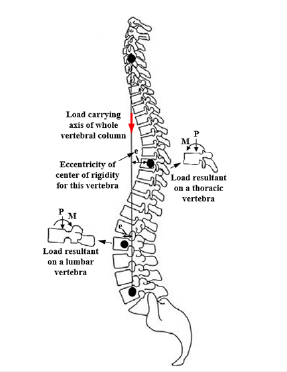
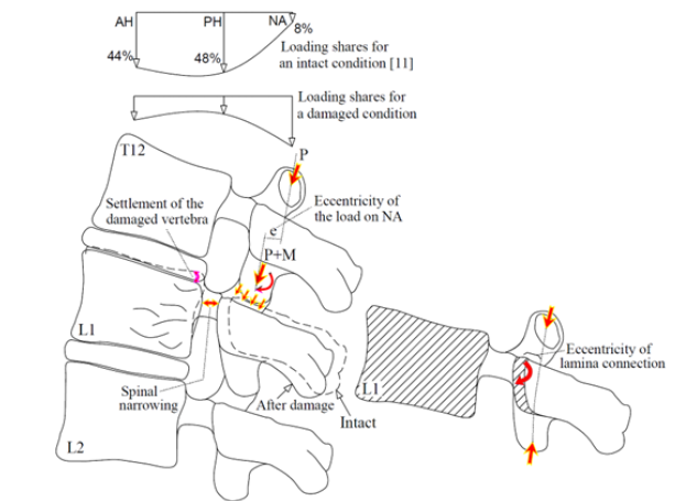
This paper aimed to describe the spinal compression mechanism for an anteroposteriorly tumor-involved vertebra. Although the effective factors for propagation of a tumor to the posterior elements of a vertebral body are not definite, this occurrence seems to increase the severity of the spinal compression, because propagation of damage to these parts is followed by instability of these components exposing the spinal canal posteriorly. Of course, this influence seems different for different levels of the vertebral column. Figure 1 shows larger deformation of an anteroposteriorly damaged thoracic vertebral body [9], in comparison to a lumbar vertebra, examined by the present study. In spite of larger deformation and failure of the thoracic vertebral body in this figure, instability of the posterior elements of the lumbar vertebra has exposed the spinal canal to larger compression. Figure 2 illustrates the cause of this different response for the vertebrae at the different levels. According to this figure, because of different natural curvature for different segments of the vertebral column, the distance between the center of rigidity for each vertebra and the load carrying axis of the whole vertebral column changes [10]. Due to this eccentricity (shown by “e” in Figure 2), in addition to the influence of axial compression, a clockwise or counterclockwise bending moment also exposes each vertebra. The existence of a clockwise bending moment for the lumbar vertebra leads to an increase in the load carrying share and stress for the posterior elements. However, for an anteroposteriorly osteolytic lumbar vertebra, the occurrence of stress-shielding in the posterior elements, a secondary bending moment on these elements seems to expose the spinal canal to a larger compression.
Figure 1:Comparison of the boundaries related to spinal stenosis around a tumor, observed for (a) a thoracic vertebra [9] and (b) a lumbar vertebra (examined in this study). (Hatched area denotes the regions involved with the tumor).
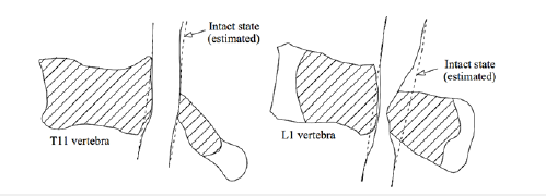
Figure 2:Schematic of a vertebral column and eccentricity for the center of rigidity of each vertebra relative to the load carrying axis of the whole vertebral column.
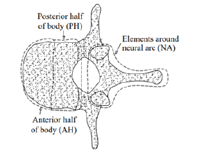
An experimental study on stress-shielding has been reported by Pollintine et al. [11] who reported an increase in the load carrying share for the posterior elements of a lumbar vertebra due to disc degeneration under an In-Vitro test. In this study, they determined three load carrying regions for each vertebra, consisting of the anterior (AH) and the posterior (PH) halves of a vertebral body and the elements around the neural arc (NA), shown in Figure 3. They used the stress profilometry technique to estimate the load carrying shares for AH, PH and NA regions equal to 44%, 48% and 8%, respectively, in an intact state and 19%, 41% and 40% after degeneration of the disc. In the present paper, it was aimed to estimate these load carrying shares for a lumbar vertebra with progressive osteolytic damage using a computational model, so the model had to simulate progressive failure of the vertebral components according to a valid scenario. In the following, some of the failure studies on the tumor-involved vertebrae are reviewed.
Figure 3:A schematic to denote the load carrying regions of a lumbar vertebra [11].
Hipp et al. [12] investigated the influence of endosteal metastatic lesions on structural consequences of long bones through observation of the In-Vitro tests and simulation of the FE models. They demonstrated the major significance of minimum wall thickness in the bone specimens for estimation of the bone strength. Mizrahi et al. [13] tried to simulate the existence of metastatic lesions in lumbar vertebrae using the 3D FE models and estimated the influence of various parameters such as location and size of lesion, modulus of the cortical and the trabecular bone and osteoporosis for prediction of the fracture load. Whyne et al. [14,15] simulated metastatically involved spinal segments by 3D poroelastic FE models to evaluate the influence of various parameters such as bone density, pedicle involvement, disc degeneration and tumor size to assess a burst fracture risk for thoracolumbar vertebrae. Tschirhart et al. [16] using the FE models demonstrated a higher risk of burst fracture for the tumors, located in the PH of a vertebral body, in comparison to the central tumors. Through another study, Tschirhart et al. [17] reported a higher risk of fracture for the upper thoracic vertebrae when involved with a tumor but a lower risk for the kyphotic motion segments. Alkaly [18] assessed the influence of lytic defects on thoracolumbar vertebral units under In-Vitro compression tests by observation of stresses and strains for the intact and artificially defected specimens. They tried to simulate the In-Vitro specimens using the nonlinear FE models and demonstrated that simulation of the lytic defects in the bones by considering a certain boundary between the healthy and lytic bones did not correspond to a real pattern of bone degradation due to a neoplastic infiltration [19,20]. Groenen et al. [21] examined the existence of a tumor for some two-level thoracolumbar vertebral units defected artificially and tried to simulate these units using nonlinear FE models, while the mechanical properties of the bony elements were determined according to the ash density using the formulae, proposed by Keyak et al. [22], Kopperdahl et al. [23] and Morgan et al. [24,25]. They compared the estimations of the models for the failure load and the stiffness with the experimental values. However, for some specimens, the estimations of the deformations were considerably different from the deformations captured by MRIs. Costa et al. [26] tried to assess the fracture risk for some metastatic vertebrae using the FE models in which the residual strength of the tumor was determined to be equal to 5% of the original bone strength. However, they did not consider a major influence on the existence of a lesion on the failure load of the metastatic vertebrae.
In the present paper, degradation of the mechanical properties in the bony elements of an osteolytic vertebral segment was simulated using a virtual thermal flux and a virtual thermal conductivity, according to the clinical report for a specific patient. Accurate simulation of the hyperelastic response for IVDs and spinal materials had a significant influence on the accuracy of the load distribution mechanism in the vertebral segment and occurrence of stress-shielding in the posterior elements of the damaged vertebra. The novel results of the paper, related to estimation of the secondary bending moment on the posterior elements and redistribution of the load on the vertebral components by progression of osteolytic damage were dependent on the accurate simulation of the interactions between the various components of the vertebral segment. The main strategy of the study was comparison of the deformations, estimated by the verified models and the capture of the MRIs to describe the mechanism of spinal compression due to instability of the vertebral components in the clinical case with anteroposteriorly osteolytic lumbar vertebra.
Clinical case of the study
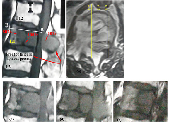
The specific case of the study, related to the subject of the paper, was a 68-year-old male, 68kg and 170cm tall, who suffered from an osteolytic lumbar vertebra due to multiple myeloma. Multiple myeloma is a hematological malignancy due to an increase in osteoclastic bone resorption and insufficient bone formation, thereby, gradual destruction of bone with the most common localization around the spine that may cause vertebral compression fracture and spinal compression [27,28]. The patient signed the consent forms to provide his results for this study. Figure 4 shows involvement of L1 vertebral body and its posterior elements with the lesion in the clinical case. In the transverse image, the location of some sagittal slices has been shown to realize the lesion front in the damaged vertebra. These figures exhibit larger progression of damage in the PH of the vertebral body and diffusion of the lesion to the posterior elements with an obvious lesion front in the spinous process. The sagittal views in Figure 4 show different densities of damage to the various regions of the damaged vertebra. The specific characteristic of the clinical case of this study, in addition to propagation of the tumor to the posterior elements of a vertebra, was the obvious front of damage in the vertebral components that allowed to depict a damage propagation pattern and compare this pattern with the available discussions on this matter. Since simulation of the osteolytic damage propagation in the vertebral components required for determination of a real scenario, using a simple image processing program, the intensity of damage to various regions of the diseased vertebra was evaluated and some of the values were shown in Figure 4(a), where the highest intensity of damage, related to complete replacement of the healthy cells by the cancerous cells, was ascribed by 100%. This pattern of damage seemed in good consistence with the configuration of a Batson’s venous plexus [29,30] and the central role of a red bone marrow [31] to spread cancerous cells. The reports on precedence of a vertebral body to the posterior elements of a vertebra to progress a tumor [32] is parallel to this scenario. Regarding this scenario, the reports of disease survival after laminectomy surgery for the patients with tumor-involved vertebra and spinal compression seem rational [33-35].
Figure 4:(a) Sagittal view from the diseased vertebral segment of the clinical case, (b) transverse view (section B-B) and location of the sagittal views, shown by (c) Sl 7, (d) Sl 5, (e) Sl 3.
For simulation of disease propagation in the models, the scenario described above was implemented. Activation of damage was determined for three regions according to the configuration of a Batson’s venous plexus inside a vertebral foramen, by a rational time sequence to consider a damage progression pattern according to Figure 4(a). The sequence of damage propagation was at first, around the basivertebral vein in the vertebral body, the second, related to the pedicle and around the vertebral foramen, and the third, in the lamina and the spinous process. Figure 5 shows a schematic of these regions for a vertebra, where t1, t2 and t3 denoted the times related to initiation of damage to these regions and tn denoted the time that was estimated for completion of damage in the vertebral body, while Db, Dp, Ds denoted the average value of the damage estimated for the volume of the vertebral body, the posterior elements and the spinous process, respectively [36]. Figure 6 shows a schematic for this mechanism. By earlier initiation of damage in region 1, according to this scenario, the PH of the vertebral body experienced some softening and settlement, followed by a backward rotation of the vertebra and a minor displacement of the center of rigidity into the posterior elements in the damaged vertebra. Through this occurrence, not only the eccentricity of the center of rigidity from the load carrying axis of the vertebral column increased, but also an additional eccentricity (“e” in Figure 6(a)) was created for the load, endured by the articular processes which exposed the posterior elements to a higher stress due to the secondary bending in addition to available compression (P+M). Pollintine et al. [11] showed that through degeneration of an IVD, the load carrying share on the posterior elements of the lumbar vertebra increased by 30% due to stressshielding. In this study using a computational model, it was tried to estimate variation of the load carrying shares for the vertebral components through propagation of the tumor. In the present mechanism, instability of the posterior elements seemed to be the major factor in the occurrence of spinal compression, so, due to the existence of the bending moment on the lamina according to Figure 6(b), the rotation of the spinous process through movement to the spinal canal was rational, according to the MRIs.
Figure 5:Schematic location of a Batson’s venous plexus in a vertebra and three regions for propagation of cancerous cells [36].
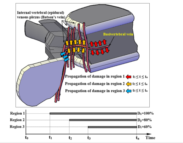
Figure 6:(a) Schematic description of the mechanism of spinal instability in an anteroposteriorly tumor involved lumbar vertebra, (b) the location of the secondary bending moment which led to rotation and movement of the spinous process to the spinal canal after softening of the lamina.
FE modeling and verification
Using a commercial package (Abaqus 6.10; Dassault Systems Simulia Corporation, Pennsylvania, USA), the FE model was generated. The geometry of the 3D models was estimated according to the 2D images captured by the MRIs, using the technique proposed by Prats-Galino et al. [37]. A three-level FE model was sufficient to examine the subject of the paper. It consisted of the diseased middle L1, surrounded by T12 and L2, while the whole segment was assumed between two rigid plates and each vertebra was surrounded by IVDs. To reduce the time of analysis, just half of the vertebral segment was modeled, while the appropriate boundary conditions were applied to the plane of symmetry. The superiority of this model was the inclusion of the posterior elements of the vertebrae. However, in many studies, the posterior elements have been removed from the models. The advantage of the rigid plates at the top and bottom ends of the model was the application of the boundary and loading conditions on these plates, so for each plate a reference point was determined, tied to the plates and the DOFs of the plates were tied to the DOFs of the reference points. The bottom reference point was fixed, while the top one was free to move vertically with a weight load equal to 2000 N [11]. The mechanical properties of the materials were assigned according to the available data in the literature, shown in Table 1; [38-46]. The IVDs were segmented into two regions of nucleus pulposus (NP) and the annulus fibrosus (AF). The hyperelastic response for these parts was determined using the second order polynomial energy functions. Existence of the collagenous fibers in the AF was the cause of its different response under tensile and compressive stresses. The same reaction was simulated using an adaptive model [47], which intelligently selected the appropriate material properties from a material library. The efficiency of this modeling procedure has been verified by a recent study [48]. The spinal canal was composed of three regions, related to white and gray materials on the inside and the subarachnoid space at the exterior region, while the hyperelastic response of the internal materials was simulated according to the data, reported by Ichihara et al. [44] and Oakland [45], and to simulate a weak response for the subarachnoid space, the mechanical properties related to a water-like material were assigned.
Table 1:Mechanical properties of the materials for different tissues in the FE model.

The mechanical properties of the ligaments have been simulated using hyperelastic functions to produce the forcedeformation response, according to the data obtained by Schmidt et al. [49]. The relation between the various components of each vertebra was determined using tie constraints. By selection of mesh size equal to 2mm for all eight-node C3D8R brick elements (with three rotational and three translational DOFs per node) of the model, based on a mesh convergence study, the total number of the elements was about 75,000. Figure 7 shows the various components and the boundary conditions for this FE model.
Figure 7:Various components of the vertebral segment and the regions of virtual thermal flux in the FE model (spinal canal was removed from view).
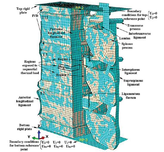
For simulation of the tumor progression and propagation in the bony elements, application of a virtual temperature in the tissues as per density of the osteolytic damage has been observed successfully [48]. Regarding the lack of knowledge on the rate of bone degradation due to osteolytic damage, by assumption of a monotonic rate, the osteolytic damage criterion for each location of the diseased tissues was determined by:

where T and Tf were the available and the final conditions of osteolytic damage through replacement of the healthy cells by the cancerous cells at any point and denoted the damage variable. The zero density of the osteolytic damage was considered by a zero temperature. The stiffness of the damaged elements was determined dependent on the damage variable according to the framework, explained in a recent study [48]. The residual strength of the bone lesion has been determined to be equal to the bone residual strength after a compressive failure, estimated by reduction of the stiffness to 1% of the original value. The values of strains, related to the initiation and completion of osteolytic damage, were determined for all bony elements equal to 0.015 and 0.034, measured for metastatic vertebral bones by Costa et al. [26]. The influence of stress-based damage was ignored for osteolytic bones. Progression and propagation of damage was simulated by assuming the values of virtual thermal conductivity ratio and virtual specific heat equal to 1 W/mK and 10 J/kg.K, respectively [48] for all bony elements of the model. By determination of a virtual thermal expansion ratio equal to zero, the influence of the virtual thermal characteristics on the mechanical stresses of the tissues was neutralized. Determination of the appropriate values for the time laps to activate damage in the various regions, shown in Figure 5, was essential since it directly influenced the softening sequence of the vertebral components and the configuration of the spinal compression. By a rough estimation of the volumes, related to Db, Dp and Ds, the damage initiation times were determined for the model. Regarding the clinical reports of the patient, the influence of any other diseases such as osteoporosis and degeneration of disc was ignored in the model.
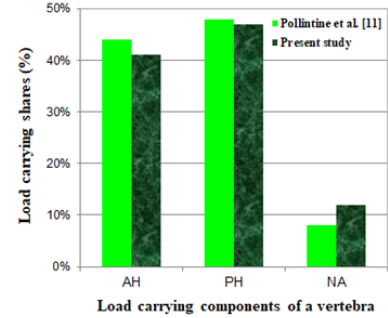
To verify the FE model, the results of load carrying shares estimated for the various vertebral components in an intact state, were compared with the similar results, obtained by Pollinitne et al. [11] using the stress profilometry technique. Figure 8 shows good accuracy of the FE results. Of course, it must be noted that the values of the load carrying shares may be different for various levels of a vertebral column because of the different geometry and eccentricity from the center of rigidity of the whole vertebral column for the different vertebrae.
Figure 8:The load carrying shares for various regions of a L1 vertebra, estimated in this study in comparison to the values, obtained by experiment [11].
Discussion of Results
In the first step, by a static analysis, deformation of the model was examined due to the weight load for the intact state of the vertebral segment. Then the sequential virtual thermal flux was activated, according to the damage propagation scenario. Initiation of damage around the basivertebral vein corresponded to the softening of the PH region in the vertebral body and stress-shielding in the other regions of the vertebra (for t1 < t < t2, 0 < Db < 20%) but there was not any compression on the spinal canal yet. Figure 9 shows the load carrying shares by three load carrying regions of the vertebra versus the increase of damage in the vertebral body (Db). This figure also shows the load carrying capacity of the vertebral segment, called strength, versus Db. Because of the activation of damage in Region 1, in spite of no influence on the strength of the vertebral segment, the load carrying share of PH considerably decreased, while there was a minor reduction in the load carrying share of AH, but a fast increase of that for NA. By increase of Db from 20%, the load carrying capacity started to decrease, however the load carrying share by NA was increasing yet. The maximum value of the load carrying share by NA reached 70% when Db=33%. Figure 10 shows the distribution of damage and deformation of the vertebral segment for four values of Db. Reduction of the load carrying share by NA corresponded to the propagation of damage to the pedicle and the top part of the lamina. Figure 10(a) shows damage to the vertebra at the time maximum load carrying share by NA. Diffusion of damage in the connection region between the superior and inferior articular processes led to the main reduction of the load carrying share by NA at Db=55%, according to the deformation shape, shown by Figure 10(c). Through enough propagation of damage in the vertebral components after Db=70%, the load carrying shares by the various regions of the vertebra seemed to be compromised. The major instability of the posterior elements and the main reduction of the strength in the vertebral segment occurred when Db=75%. Figure 10(d) shows the distribution of damage and spinal compression, related to this description. Figure 11 shows a good agreement between the deformations, captured by the MRI and estimated by the FE model for the damaged vertebra and the spinal canal when Db=75%.
Figure 9:Variation of load carrying share for the various load carrying regions of the damaged vertebra (L1) versus increase of Db. (Figure 10 shows the state of damage, associated to each letter, shown in this figure).
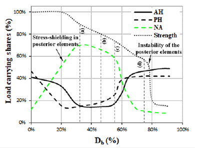
Figure 10:Propagation of damage for the vertebral components when (a) Db=35%, (b) Db=45%, (c) Db=55%, (d) Db=75%. (Figure 9 shows the reduction of the strength associated with the letters in this figure. Ligaments were removed from the view)
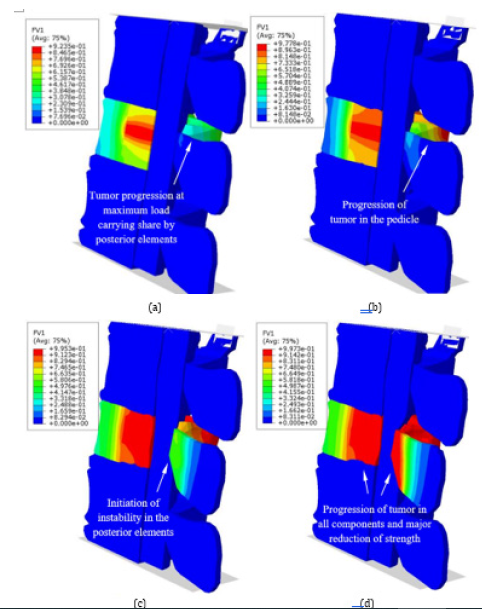
Figure 11:Comparison of the boundaries of deformations in the damaged vertebra and the spinal canal, estimated by the FE model for Db=75% and the MRI.
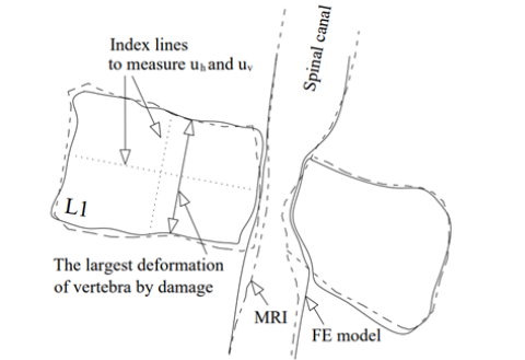
Figure 12:(a) Horizontal and vertical deformations versus the average damage index in the vertebral body (Db), (b) the values of average damage and the secondary bending moment in the posterior elements of the vertebra versus Db.
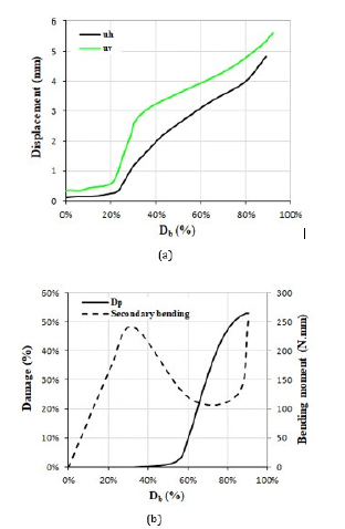
In some studies, to assess the risk of fracture in the vertebral body and the endplates, the values of vertebral bulge and vertical deformation have been observed in the FE models [14,50]. Figure 12 shows the vertical (uv) and horizontal (uh) deformations of the damaged vertebra in the present study on the plane of symmetry versus increase of Db. Figure 12 shows the index lines for measurement of uh and uv. This figure showed a minor range of deformations of the damaged vertebra, even after the major involvement of the vertebral body with a lesion, so the deformation of the vertebral body seemed to have a minor influence on the occurrence of a severe spinal compression rather than the major influence of the posterior elements of the vertebra. Figure 12(b) shows the average value of damage in the posterior elements (Dp) versus increase of Db. According to this figure, the rate of damage in the posterior elements increased considerably because of activation of the damage in region 3. The same figure shows the amount of the secondary bending moment (M) on the superior articular process of L1 vertebra, shown in Figure 6(b), versus the increase of Db. The amount of secondary bending moment in this figure was calculated equal to the value of the axial load on NA multiplied by the value of the eccentricity for the superior articular process from its original location in the intact state. According to this figure, through the increase of Db up to 30%, the amount of the secondary bending moment was increased, however for Db=30%-70%, reduction of the load carrying share by NA led to reduction of this bending moment.
The latter part of this graph showed considerable increase in this bending moment due to instability of the posterior elements when the lesion diffused enough to the connection region between the superior and inferior articular processes in the damaged vertebra. The same bending moment led to rotation and movement of the spinous process and exposing the spinal canal to a large compression. The values of the secondary bending moment, shown in Figure 12(b), were enough to cause instability of the posterior elements after softening. The interaction, simulated in this study between the spinal canal and the vertebrae seemed a most accurate one in comparison to the prior simulations [51,52].
Summary and Conclusion
The purpose of this study was a computational investigation into the spinal compression mechanism around an anteroposteriorly tumor-involved lumbar vertebra and the strategy for verification of the estimations was comparison of the deformations in the vertebral components, obtained by the model with the MRIs. An appropriate clinical case for the subject with multiple myeloma was selected to be simulated. Because the occurrence of spinal compression was attributed to degradation of the mechanical properties in the osteolytic vertebra, dependent on a virtual temperature, progression and propagation of disease was determined according to the available reports of failure of the In-Vitro test specimens under mechanical loads and spreading of cancerous cells in a Batson’s venous plexus. The hyperelastic response for the IVDs and the spinal materials was simulated using the second order polynomial energy functions to observe an accurate load transmission mechanism by the model. The load carrying characteristics of the lumbar vertebra estimated by this model were consistent with those reported for In-Vitro test specimens.
The model could simulate stress-shielding in the posterior elements of the damaged vertebra due to earlier occurrence of damage in the vertebral body and estimate an increase in the load carrying share by the posterior elements equal to 58%. Diffusion of the osteolytic damage to the posterior elements was followed by instability and displacement of the spinous process to the spinal canal. The low values of axial and bulge deformations in the damaged vertebral body indicate the significant influence of the posterior elements of a vertebra if involved with osteolytic damage, causing more severe spinal compression. The computational model developed in this study seemed sufficient for prediction of a spinal compression configuration due to progression of osteolytic damage in the various levels of the vertebral column.
Ethics Statement
All research will be conducted with an ethic of respect for cultures, communities, the individual/person, and independent knowledge. This ethic of respect informs our approach to research design and the development of our projects at every stage.
Acknowledgement
The author would like to thank Dr. M. Pourghasemian from Department of Internal Medicine in Ardabil University of Medical Sciences for his helpful advice related to the clinical case study. The author, however, bears full responsibility for the paper.
Declaration of Funding and Competing Interests
The author received no financial support for the research, authorship, and/or publication of this article. Also, the author has no conflict of interest to declare.
References
- White III AA, Panjabi MM (1990) Clinical biomechanics of the spine. JB Lippincott Company.
- Van Goethem JWM, van den Hauwe L, Özsarlak Ö, De Schepper AMA, Parizel PM (2004) Spinal tumors. Eur J Radiol 50: 159-176.
- Nguyen TT, Thelen JC, Bhatt AA (2020) Bone up on spinal osseous lesions: a case review series. Insights into Imaging 11(1): 80.
- Krishnaney AA, Steinmetz MP, Benzel EC (2004) Biomechanics of metastatic spine cancer. Neurosurg Clin N Am 15(4): 375-
- Benzel EC (2001) Trauma, tumor and infection, in: Biomechanics of spine stabilization, Rolling Meadows, IL: American Association of Neurological Surgeons, pp: 61-82.
- Ṣincari M, Cabrita F, P Gabriel, Nunes AF (2023) Severe spine cord compression by plasmacytoma/multiple myeloma, Series of Cases. Tech Neurosurg Neurol 5(4).
- Roodman GD (2004) Mechanisms of bone metastasis. N Engl J Med 350(16): 1655-1664.
- Jiang K, Liang L, Lim CT (2021) Engineering confining microenvironment for studying cancer metastasis. iScience 24(2): 102098.
- Chen CJ, Yan TB, Liu YD, Wang Y, Zhao X, et al. (2023) Multiple myeloma rather than metastatic lung cancer: an unexpected cause of spinal cord compression. World J Oncol 14(5): 438-442.
- Benzel EC (2001) Biomechanics of spine stabilization. Thieme, New York, USA.
- Pollintine P, Dolan P, Tobias JH, Adams MA (2004) Intervertebral disc degeneration can lead to “stress-shielding” of the anterior vertebral body. Spine 29(7): 774-
- Hipp JA, McBroom RJ, Cheal EJ, Hayes WC (1989) Structural consequences of endosteal metastatic lesions in long bones. J Orthop Res 7(6): 828-
- Mizrahi J, Silva MJ, Hayes WC (1992) Finite element stress analysis of simulated metastatic lesions in the lumbar vertebral body. J Biomed Eng 14(6): 467-
- Whyne CM, Hu SS, Lotz JC (2003) Burst fracture in the metastatically involved spine: development, validation, and parametric analysis of a three-dimensional poroelastic finite-element model. Spine 28(7): 652-
- Whyne CM, Hu SS, Lotz JC (2001) Parametric finite element analysis of vertebral bodies affected by tumors. J Biomech 34(10): 1317-
- Tschirhart CE, Nagpurkar A, Whyne CM (2004) Effects of tumour location, shape and surface serration on burst fracture risk in the metastatic spine. J Biomech 37(5): 653-
- Tschirhart CE, Finkelstein JA, Whyne CM (2007) Biomechanics of vertebral level, geometry, and transcortical tumors in the metastatic spine. J Biomech 40(1): 46-
- Alkalay RN, Harrigan TP (2016) Mechanical assessment of the effects of metastatic lytic defect on the structural response of human thoracolumbar spine. J Orthop Res 34(10): 1808-1819.
- Whyne CM, Hu SS, Wolkman KL, Lotz JC (2000) Biphasic material properties of lytic bone metastases. Ann Biomed Eng 28(9): 1154-1158.
- Hipp JA, Katz G, Hayes WC (1991) Local demineralization as a model for bone strength reductions in lytic transcortical metastatic lesions. Invest Radiol 26: 934-938.
- Groenen KHJ, Bitter T, van Veluwen TCG, van der Linden YM et al. (2018) Case-specific non-linear finite element models to predict failure behavior in two functional spinal units. J Orthop Res 36(12): 3208-3218.
- Keyak JH, Kaneko TS, Tehranzadeh J, Skinner HB (2005) Predicting proximal femoral strength using structural engineering models. Clin Orthop Relat Res (437): 219-228.
- Kopperdahl, DL, Morgan EF, Keaveny TM (2002) Quantitative computed tomography estimates of the mechanical properties of human vertebral trabecular bone. J Orthop Res 20(4): 801-805.
- Morgan EF, Bayraktar HH, Keaveny TM (2003) Trabecular bone modulus-density relationships depend on anatomic site. J Biomech 36(7): 897-904.
- Morgan EF, Keaveny TM (2001) Dependence of yield strain of human trabecular bone on anatomic site. J Biomech 34(5): 569-577.
- Costa MC, Eltes P, Lazary A, Varga PP, Viceconti M, et al. (2019) Biomechanical assessment of vertebrae with lytic metastases with subject-specific finite element models. J Mech Behav Biomed Mater 98: 268-290.
- Palmbach M, Hoffmann W, Grodd W, Postler E, Voigt K (1996) Extraosseous, epidural tumor spread of multiple myeloma. Eur J Radiol 22: 146e8.
- Panaroni C, Yee AJ, Raje NS (2017) Myeloma and bone disease. Curr Osteoporos Rep 15(5): 483-498.
- Morgan JW, Adcock KA, Donohue RE (1990) Distribution of skeletal metastases in prostatic and lung cancer. Mechanisms of skeletal metastases. Urol 36(1): 31-34.
- Gowin W (1983) Significance of the venous system of the spine in the formation of metastases (in German). Strahlentherapie 159(11): 682-689.
- Taneichi H, Kaneda K, Takeda N, Abumi K, Satoh S (1997) Risk factors and probability of vertebral body collapse in metastases of the thoracic and lumbar spine. Spine 22: 239-
- Coman DR, Delong RP, Mccutcheon M (1951) Studies on the mechanisms of metastasis; the distribution of tumors in various organs in relation to the distribution of arterial emboli. Cancer Res 11(8): 648-651.
- Gilbert RW, Kim JH, Posner JB (1978) Epidural spinal cord compression from metastatic tumor: diagnosis and treatment. Ann Neurol 3(1): 40-51.
- Greenberg HS, Kim JH, Posner JB (1980) Epidural spinal cord compression from metastatic tumor: results with a new treatment protocol. Ann Neurol 8(4): 361-366.
- Young RF, Post EM, King GA (1980) Treatment of spinal epidural metastases, Randomized prospective comparison of laminectomy and radiotherapy. J Neurosurg 53(6): 741-
- Batson OV (1940) The function of the vertebral veins and their role in the spread of metastases. Ann Sur 112: 138.
- Prats-Galino A, Mavar M, Reina MA, Puigdellívol-Sánchez A, San-Molina J, et al. (2014) Three-dimensional interactive model of lumbar spinal structures. Anaesthesia 69: 521.
- Lu YM, Hutton WC, Gharpuray VM (1996) Can variations in intervertebral disc height affect the mechanical function of the disc? Spine 21: 2208-2216.
- Lu YM, Hutton WC, Gharpuray VM (1996) Do bending, twisting, and diurnal fluid changes in the disc affect the propensity to prolapse? A viscoelastic finite element model. Spine 21: 2570-2579.
- Shirazi-Adl A, Ahmed AM, Shrivastava SC (1986) Mechanical response of a lumbar motion segment in axial torque alone and combined with compression. Spine 11: 914-927.
- Yamada H (1970) Strength of biological materials. Evans FG (Ed.), The Williams & Wilkins Company, Baltimore.
- Natarajan RN, Andersson GB (1999) The influence of lumbar disc height and cross-sectional area on the mechanical response of the disc to physiologic loading. Spine 24: 1873-1881.
- Wu HC, Yao RF (1976) Mechanical behavior of the human annulus fibrosus. J Biomech 9(1): 1-7.
- Ichihara K, Taguchi T, Shimada Y, Sakuramoto I, Kawano S, Kawai S (2001) Gray matter of bovine cervical cord is mechanically more rigid and fragile than white matter. J Neurotrauma 18(3): 361-367.
- Oakland RJ, Hall RM, Wilcox RK, Barton DC (2006) The biomechanical response of spinal cord tissue to uniaxial loading. Proc Inst Mech Eng H: J Eng Med 220(4): 489-492.
- Khuyagbaatar B, Kim K, Hyuk-Kim Y (2014) Effect of bone fragment impact velocity on biomechanical parameters related to spinal cord injury: A finite element study. J Biomech 47(11): 2820-2825.
- Nazari AR, Khanzadeh-Moradllo M (2023) Developing an adaptive FE model to reflect the effective mechanical properties in porous elastomeric materials. J Cell Plast 59(1): 3-27.
- Nazari AR (2024) Simulation of cancer progression in bone by a virtual thermal flux with a case study on lumbar vertebrae with multiple myeloma. Med Eng Phys 126: 104147.
- Schmidt H, Heuer F, Drumm J, Klezl Z, Claes L, Wilke H-J (2007) Application of a calibration method provides more realistic results for a finite element model of a lumbar spinal segment. Clin Biomech 22(4): 377-384.
- Salvatore G, Berton A, Giambini H, et al. (2018) Biomechanical effects of metastasis in the osteoporotic lumbar spine: A Finite Element Analysis. BMC Musculoskelet Disord 19: 38.
- Diotalevi L, Bailly N, Wagnac É, Mac-Thiong J-M, Goulet J, Petit Y (2020) Dynamics of spinal cord compression with different patterns of thoracolumbar burst fractures: Numerical simulations using finite element modelling. Clin Biomech 72: 186-194.
- Greaves CY, Gadala MS, Oxland TR (2008) A three-dimensional finite element model of the cervical spine with spinal cord: an investigation of three injury mechanisms. Ann Biomed Eng 36(3): 396-405.
© 2024 Ali Reza Nazari. This is an open access article distributed under the terms of the Creative Commons Attribution License , which permits unrestricted use, distribution, and build upon your work non-commercially.
 a Creative Commons Attribution 4.0 International License. Based on a work at www.crimsonpublishers.com.
Best viewed in


.jpg)


 Editorial Board Registrations
 Submit your Article
 Refer a Friend
 Advertise With Us
.jpg)


.jpg)


.bmp)
.jpg)
.png)
.jpg)


.png)

.png)


.png)


