
- About Us
- Information
-

The Author ensures that the research has been conducted responsibly and ethically with adherence to all relevant regulations. read more..
- For Authors
- For Reviewer
- Manuscript Guidelines
- Membership
- Publication Ethics
-
- Journals
- Reprints
- e-Books
- Videos
- Policies
- Contact Us
 COVID-19
- Submissions


Full Text
Orthopedic Research Online Journal
Early Bioengineering Research in Orthopedics-A Historical Report of Personal Experience
John N Hatzopoulos1,2*
1Professor Emeritus at the University of the Aegean, Greece
2Former Professor at California State University, USA
*Corresponding author:John N Hatzopoulos, PhD, Professor emeritus at the University of the Aegean, Greece
Submission: May 05, 2021;Published: June 01, 2021

ISSN: 2576-8875 Volume8 Issue2
Abstract
It was 1975 when I joined as a graduate student on a research team at the University of Washington, Seatle USA. I worked under the supervision of professor Sandor Veress at the Department of Civil Engineering. At that time, it was the Vietnam war, and many veterans were suffering various injuries. Therefore, there were several research projects with joint research between the Swedish Medical Center, the Veterans Administration Hospital, and the University of Washington in Seattle dealing with orthopedics. I was already a graduate of the Rural and Surveying Engineering Department at the Technical University of Athens and a licensed surveyor in Greece. Because of my qualifications, I was involved in two such research projects. One was to perform external measurements and mapping the human body using close-range photogrammetry with simultaneous exposures of overlapping photographs. The other was internal measurements and mapping the human body using X-ray photogrammetry with simultaneous exposures of overlapping X-ray images from two anodes. The first project was based on the theory of Dr. Ernest M. Burgess, M.D., head of the Swedish Medical Center: by knowing the shape of a below-the-knee amputated leg in two extreme macules states of contract and relax position, he could design a prosthesis for better physiologic support. The other project used X-rays to map and monitor the hip joint replacement and also study the patella movement.
Introduction
The research project was funded by a grant from the National Science Foundation. The supervisors in the joint research were: Ernest M. Burgess. M. D., head of Prosthetics Research at the Swedish Medical Center, provided patients, material, and assistance to execute practical experimentation. Dr. F. G. Lippert, M. D., Ph.D., supervised the medical procedures and execution of the research. The major emphasis was on the surgical technique of implementation of permanent landmarks into the skeleton system. Further, he selected patients, performed the required surgery, and evaluated the results. He also offered to us (graduate students) a course in anatomy to better communicate with the doctors. Dr. S. A. Veress, D.Sc., supervised the engineering part of the research. The major emphasis was on the establishment of the Biomedical Laboratory for general studies, emphasizing motion studies. Further, he supervised and formulated the process of x-ray photogrammetry.
The research team from the UW Civil Engineering Department under professor Veress supervision had the following graduate students (Ph.D. candidates):
1. Takenori Takamoto, from Japan working on X-rays, was responsible for developing methodology and computer programs. He executed the experimentation for analytical and stereo x-ray photogrammetry.
2. Rama Tiwari, from India, was responsible for developing computer programs for the analytical process of external photogrammetry and computer graphics. Further, he performed the calibration of the camera frame and the X-ray frame together with the control points. He was involved in both external and internal measurements.
3. John N. Hatzopoulos, from Greece, was responsible for the calibration and recalibration of the external photogrammetry laboratory. He designed a special plotter for the graphical evaluation. He also did run the X-ray system and simplified the mathematical formulation of the X-ray photogrammetric process.
4. C. H. Schuch, (MS candidate) was responsible for further refinements to the x-ray photogrammetry considering: programs and auxiliary equipment.
5. Clive Fraser, from Australia worked on camera calibration.
6. Riadh Munjy, from Iraq worked also on camera calibration.
7. Qassim A. Abdullah, from Iraq worked on X-ray photogrammetry.
Further information about these two photogrammetry methods in orthopedics is discussed in the present report.
The external close-range photogrammetry measuring system
The one working on the development of this system was Rama Tiwari, and he trained me to operate it. There were several patients with a below-the-knee amputated leg, and we measured the stump. The external elements of the human body, like the stump, are dynamic. Therefore, photogrammetric measurements have to be performed on two stereo photographs using two synchronized cameras for simultaneous exposures, as shown in Figure 1.
The patient stump was placed in a stand surrounded by control points measured by theodolite with high accuracy of 0.1mm. Rama Tiwari was responsible for the measurements [1]. Figure 2 shows the preparation of the patient to take the photographs. Notice some self-adhesive targets being attached to the stump to increase the contrast. I performed the photogrammetric mapping on an instrument I designed for that purpose, and it was a part of my Master thesis [2]. Figure 3 shows the results of mapping the stump.
Figure 1: Two Hasselblad MK70 cameras in stereo position synchronized for simultaneous exposures for exterior measurements on the human body.

Figure 2: Preparation to take photographs for external measurements on the human body.

Figure 3: Topographic map of the stump at relax position on the left and contract position on the right.

X-ray photogrammetry system for internal measurements.
Takenori [3] and Rama Tiwari were working on this system. Takamoto was working on implementing mathematics in the computer, Tiwari was working on the design and calibration of the control frame. This system also had several patients and was developed to run regularly. When Takamoto obtained his Ph.D. degree, he left, and Tiwari called to run the system. When Tiwari obtained his Ph.D. degree, also he left, and I was called to run the system. I had no such training, so I had to study Takamoto’s dissertation. By doing so, I discovered that mathematics was more complicated than necessary. Indeed was using rotational angles, which for the X-ray anods had no reason to exist. The results were correct, but the process was complicated, resulting in many lines of Fortran code to implement in the computer. However, I reformulated the entire process, and I wrote a minimal computer program to obtain the same results. Professor Veress was excited about the new method and asked me to maintain secrecy because UC Berkeley was doing similar work and could take our method.
I was also removed from the project, which was all right because I worked on another project for structural monitoring under professor Veress’s supervision. Consequently, the math I developed was used by Qassim A. Abdullah in his dissertation. I finish my Ph.D. December 1979 and by January 1980, I was hired as an associate professor at the California State University Fresno Civil Engineering Department. In the Fall of 1988, there was a Southern California conference by the ASPRS Chapter. I was astonished to see a UC Berkeley professor presenting the same method I developed in 1979 as their achievement. For the historical reason, I present below the method I developed. I also must point out the excellent idea of Takenori Takamoto and Rama Tiwari on the design and calibration of the control frame. Figure 4 shows a system composed of two X-ray anodes Ο1 and Ο2 and a control frame composed of two parallel planes with control points. Plane (2) supports the coordinate system and the fiducial marks of 5, 6, 7, 8. Plane (3) supports the control points 1, 2, 3, 4. The frame was calibrated using a theodolite and a three-dimensional intersection to calculate (X, Y, Z) coordinates of all control points and all fiducial marks, as shown in Figure 4. The precision of such measurements was 0.1mm. The X-ray film was located in the plane (1), which is parallel to planes (2) and (3). The frame with all control points was manufactured from Plexiglas, being material of low conductivity. Its parts are glued together to minimize distortion through time. The control frame allowed the plane’s (3) removal and put it back precisely in the same position. Plane (3) is necessary to strengthen the geometry of resection. The process of internal surveying had the following steps:
Figure 4: Photogrammetric surveying system of interior elements of the human body with X- rays.

1. Place frame with both levels (2) and (3) and exposure the film simultaneously by the two anodes.
2. Measure all points imaged by anode Ο1 in the film (1′, 2′, …, 8′) and all points imaged by anode Ο2 (1′′, 2′′, …, 8′′).
3. Using the measurements of the fiducial marks of 5, 6, 7, 8 in step 2, calculate the transformation coefficients of all coordinates. Then transform the coordinates of all points into the coordinate system located on the plane (2).
4. Calculate anode position by resection as follows: for each control point, are known the coordinates (X, Y, Z) of the plane (3) from the calibration data and coordinates (x, y, 0) on the plane (2) as calculated in step 3.
Therefore, for each control point, we write the following two equations:
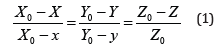
Where Χο, Υο, Ζο are the coordinates of the anode where the perspective center is located. Relations (1) are two equations written as follows:
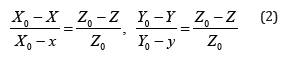
Equations (2) are linear, and with four control points, we create eight equations with three unknowns. We use least-squares adjustment to determine the perspective centers Ο1 and Ο2.
1. Remove plane (3) from the frame with the control points and position on the plane (2) the part of the human body to be internally measured. Make a simultaneous exposure of both anodes.
2. Measure the fiducial marks, as in steps 2 and 3, then measure all points of the human body as projected by both anodes on the film.
3. Convert all measured coordinates to plane (2) using the fiducial marks, as in step 3. Each point of the human body has two sets of image coordinates. The one set is (x′, y′, 0) from anode 1, and the other set is (x′′, y′′, 0) from anode 2.
4. Calculate three-dimensional coordinates of all human body points by an intersection as follows: For each object-point, we write two equations of the form (2) where the coordinates (Xo, Yo, Zo) for each anode are known from step 4, and (x, y) point coordinates have been calculated in step 7. With two anodes for each point, we have four equations of the form (2) with three unknowns (X, Y, Z). A least-squares adjustment solves the system, and the coordinates (X, Y, Z) of each point are calculated. Notice that the most challenging part of the measuring process is to recognize points of the human body in both images, which are provided by corresponding anodes. However, this process has been evolved and has been significantly improved by automated pattern recognition techniques to create a 3-D point cloud of parts of the human body.
References
- Veress SA, Tiwari RS, Hatzopoulos JN (1976) Mapping of stump using close-range Proceedings of the ASP Fall Convention Seattle WA.
- Veress SA, Hatzopoulos JN (1978) A plotting instrument for close-range photogrammetry. Photogrammetric Engineering and Remote Sensing 44(3): 273-283.
- Veress SA, Lippert FG II, Takenori T (1977) An analytical approach to x-ray photogrammetry. Photogrammetric Engineering and Remote Sensing 43(12): 1503-1510.
© 2021 John N Hatzopoulos. This is an open access article distributed under the terms of the Creative Commons Attribution License , which permits unrestricted use, distribution, and build upon your work non-commercially.
Editor In Chief


.jpg)


Signup for Newsletter

Quick Links
 Editorial Board Registrations
 Submit your Article
 Refer a Friend
 Advertise With Us
Our Recent Edition

.jpg)


Top Editors


.jpg)


.bmp)
.jpg)
.png)
.jpg)


.jpg)


.png)

.png)


.png)


Financial Support

Sponsors

Latest e-Books

Latest Video

 a Creative Commons Attribution 4.0 International License. Based on a work at www.crimsonpublishers.com.
Best viewed in
a Creative Commons Attribution 4.0 International License. Based on a work at www.crimsonpublishers.com.
Best viewed in