
- About Us
- Information
-

The Author ensures that the research has been conducted responsibly and ethically with adherence to all relevant regulations. read more..
- For Authors
- For Reviewer
- Manuscript Guidelines
- Membership
- Publication Ethics
-
- Journals
- Reprints
- e-Books
- Videos
- Policies
- Contact Us
 COVID-19
- Submissions


Full Text
Open Access Biostatistics & Bioinformatics
On Modeling Water Transport in Polymer Electrolyte Membrane Fuel Cell
Ahmed Kaffel*
Department of Mathematics, Statistics & Computer Science, Marquette University, USA
*Corresponding author: Ahmed Kaffel, Department of Mathematics, Statistics & Computer Science, Marquette University, 1313 W. Wisconsin Avenue, Cudahy Hall, Milwaukee, USA
Submission: December 08, 2017; Published: January 03, 2018

ISSN: 2578-0247Volume1 Issue1
Abstract
There is a great need to predict liquid water saturation in porous layers such as gas diffusion layers (GDL) and micro porous layers (MPL) of polymer electrolyte membrane fuel cells (PEMFCs) as this is a key parameter in flooding occurrence which is a limiting factor of PEM fuel cell performance. Several models have been developed in order to study water distribution and migration in micro porous layers. These models require heavy computational efforts and doubt in their applicability to the gas diffusion layer (GDL). Recently Qin & Hassanizadeh [1] developed a new approach based on the reduced continua model for modeling multiphase flow through a stack of thin porous layers. Their approach requires much less computational efforts and predicts less water flooding in the GDL, but is using an empirical closure inaccurate model.
In this work, a volume averaging approach is developed and applied to the microscopic mass balance equations for transforming the threedimensional point wise equations to two dimensional averaged equations. An explicit closure model for the interlayer mass exchange of liquid will also be constructed. The resulting equations consist of macroscopic mass balance equations combined with a series of constitutive relationships. The obtained 2D model will enormously improve the computational speeds, allowing the users to obtain faster, reasonably accurate simulations at lower cost. A numerical algorithm will be developed and the effects of major material parameters of the macroscopic model on water flooding in the GDL and MPL layers will be investigated.
Introduction
Fuel cells have potential and diverse applications which can be classified into three main areas: transportation, stationary power generation, and portable applications; in the transportation sector, fuel cells are probably the most serious contenders to compete with internal combustion engines (ICEs). Fuel cells are considered as the only viable technical solution to the problem of car-related pollution, this is due to its zero/ultralow emissions and high efficiency [2,3]. Stationary power generation is viewed as the leading market for fuel cell technology other than buses. The reduction of CO2 emissions is an important argument for the use of fuel cells in small stationary power systems, particularly in combined heat and power generation (CHP). Portable fuel cells are very useful in areas where grid power is non-existent, unavailable or undependable. They can provide reliable, high quality power in emergency and non-emergency situations, such as hurricanes, earthquakes, fires and ice storms, remote construction sites, camping, yachting, and traffic monitoring.
A typical PEMFC unit consists of gas channels (GCs), gas diffusion layers (GDLs), micro porous layers (MPLs), and catalyst layers (CLs) on both cathode and anode sides. The two sides are connected by a solid polymer electrolyte membrane (PEM). Pure hydrogen or reformed hydrogen from fossil fuels (e.g. natural gas) is used as the anode fuel and the cathode can be operated with air as the oxygen source Figure 1. The electrochemical reduction reaction of oxygen (ORR) and the oxidation reaction of hydrogen (HOR) are shown in Figure 1.
Figure 1: Cross-section of a polymer electrolyte membrane fuel cell (microscopic image courtesy of ZSW Ulm) [6].

Despite many potential benefits, i.e. its high efficiency, low/ zero emission and quick startup, and because of the high cost of the materials used (eg. ionomer materials and platinum- based catalysts) and the low reliability of the devices, the large- scale commercialization of PEMFCs is still restricted. Currently, active research is underway to reduce the cost by reducing the loading of the platinum catalyst, seeking inexpensive materials and construction methods, and improving cell performance and durability [4-7]. Any improvement, such as reducing the cost by reducing the loading of the platinum catalyst or searching for low- cost materials/fabrication methods, will increase the acceptance of fuel cells. Therefore, attempts are being made towards improving the cell's performance and durability. Cathode performance also plays vital role in the fuel cell's performance.
One of the significant technical challenges is the formation of excess water in the PEMFC. This water formation is due to water production from the oxygen reduction reaction ORR at the cathode. This leads to the filling of the pores in the gas diffusion layer (GDL). Once the pores are filled with water, the transport of oxygen to the catalyst layer (CL) gets blocked. The catalyst sites then get covered. The overall effect is a reduction in the fuel cell performance. This effect is referred to as GDL/MPL and CL flooding. Furthermore, in a PEMFC, if the accumulation of water reaches a point where water columns or water bands from inside the flow channels, gas flow becomes blocked or clogged. In addition, water flooding within the catalyst layer, GDL and/or gas flow channels can result in a nonuniform distribution of reactants over the active catalyst area and among cells in the stack. This leads to both poor performance and cell-to-cell performance variation within a stack [8,9]. Therefore, water flooding will make the cell performance unpredictable, unreliable and unrepeatable under nominally identical operating conditions [10,11]. As a result, maintaining the proper balance in the fuel cell between water production and removal is essential in optimizing PEM fuel cell performance.
This paper will examine the water management which is a critical challenge for the high performance of polymer electrolyte membrane fuel cells (PEMFCs). Our goal is to focus on quantifying the distribution and migration of liquids in various layers of a PEMC, such as the gas diffusion layers (GDL) and the micro porous layers (MPL), which is of great interest and very useful for modeling water transport in PEMFCs and for studying flooding phenomenon which would result in reactant transport limitation and cell degradation.
Several models have been developed in order to predict the water dynamics in thin porous layers. These models require heavy computational efforts and there is doubt in their applicability to the gas diffusion layer (GDL).
Studies on the water flooding phenomena have ranged from numerical simulation and prediction (modeling), to experimental investigation and diagnosis, with the ultimate goal of developing mitigation strategies. One of the most commonly approach used is the Continuum model [12] used in many applications involving porous media. The porous medium is treated as a hypothetical effective continuum. The models rely on phenomenological relationships such as the generalized Darcy’s law. Key parameters in this approach are the permeability, relative permeability and the capillary pressure-saturation curve.
The three dimensional (3D) Darcy-based models are formulated in terms of averaged quantities [13,14], they are defined over an averaging domain known as the representative elementary volume (REV). The poor predictions of traditional Darcy-based models were proved based on the pore-scale pore-network modeling of water transport in a GDL [15]; the lack of a significant length scale separation between the pore scale and the GDL thickness which, among other things, leads to scale dependent transport properties plus the domination of capillary effects on the invasion regime. An alternative approach is the direct simulations [16,17]. The main objective is to compute the two-phase flow by solving directly the problem at the pore scale. This can be performed using for example a Lattice Boltzmann model [18].
Due to the limitations of continuum models, pore network models (PNMs) appear as a good settle between accuracy and computational effort. Rebai & Prat [15] proved the poor prediction of the traditional continuum model and studied several effects on water transport in GDL. In their paper, they studied the scale effect associated with the thin nature of GDL, lack of length scale separation which leads to scale dependent transport properties and how considering the water invasion process depending on the values of the capillary number is a second lack of length scale separation. Pore network models are a good tool to determine the parameters needed in the traditional continuum approach and gaining a better understanding of the phenomena occurring at the pore network scale. But the problem with such approach is not taking consideration of water generation and transport in the adjacent porous layers which result in an inappropriate analysis of water transport in a GDL.
A new approach has been developed by Qin & Hassanizadeh [1] called reduced continua model in which each layer was modeled as a 2D domain with governing equations formulated in terms of thickness-averaged properties. This approach was implemented for the case of modeling liquid water flooding in the GDL and micro porous layer MPL of a PEMFC. Using the assumption of uniform water influx the 2D domain was reduced to two interacting 1D domains. In [19], numerical studies using the Richards model (a traditional Darcy-based model) were conducted against the reduced continua model in order to present the difference between them and illustrate the advantages of the new approach.
Conventionally PEMFC models in the literature are assumed to be isothermal because of small heat generation at low to medium current densities. Nguyen and White [20] presented one of the first non-isothermal models for a PEMFC. The governing equation for heat transport is only a coarse approximation as they assume an overall heat transfer coefficient for the PEMFC. Only latent heat of vaporization is considered in their model, neglecting major heat sources associated with the electrochemical reactions.
Most of the models assume local thermal equilibrium, i.e., local temperatures are the same for all phases. A few models however assume local thermal non-equilibrium and solve separate heat transport equations (temperatures) for the solid and fluid phases [21].
Rowe & Li [22] performed a two-phase, non isothermal model. Their model included various heat sources i.e. reversible and irreversible heats associated with the electrochemical reactions, ohmic heating due to proton transport and heat released/absorbed due to phase change of water. If suitable hydration is not maintained in the anode electrodes, the cell performance drops significantly. Wang et al. [23] developed a three-dimensional non-isothermal model and validated against experimental data by varying operating temperatures, pressures and humidification. In their model, reversible heat of reaction and ohmic heating due to electron transport are not considered. Fuel cell performance is found to be increasing with operating temperatures in case of sufficient humidification. Ju et al. [24] presented a three-dimensional, singlephase, non-isothermal model for a PEMFC. They took into account the entropic heat, irreversible heat of reaction and ohmic heating. They applied their model on a 50cm2 segmented cell and validated their model predictions against experimental data by varying cell voltages and humidity conditions. Pasaogullari et al. [25,26] developed a two-phase, non-isothermal model for a cathode GDL only, considering anisotropic heat transport. An anisotropic GDL is found to be more prone to flooding than an isotropic GDL. Zamel & Li [27] built a two-phase, non-isothermal model of the cathode electrode with the highest temperatures observed in the catalyst layer.
One of the main goals in fuel cell design is to maintain a proper water balance in all components in order to optimize the performance and extend the durability of the PEMFC. In order to avoid membrane dehydration and mass transport limitations, we need to deeply understand the liquid water evolution inside the PEMFC.
Over the past decade, tremendous efforts have been paid to the numerical modeling of liquid water flooding in the diffusion layers of a PEMFC. Due to the problems and doubts encountered when working with the traditional Darcy-based 3D model, our new model came as a good alternative. We have proposed a new approach based on a reformulation of macroscale governing equations by employing the averaging thermodynamics approach. Based on a REV defined for each layer, microscale transport equations were averaged over the layer thickness. This model will be applied to model water and heat transport between different layers of the fuel cell. The new approach is formulated in terms of layer-thickness- averaged material properties which are usually easily measurable. This model showed less computational efforts requirement and predicted less water flooding in the GDL especially under the channel area. This approach is an extension of the reduced continua model developed by Hassanizedeh et al. [28]. Our model is considered reasonably accurate compared to the reduced continua model. Our goal will be to build an accurate 2D model starting from a 3D model using explicit expressions for modeling the mass exchange between layers using the new approach developed recently. The obtained model will enormously improve the computational speeds, allowing the users to obtain faster, reasonably accurate simulations at lower cost. We will focus on the effect of major material parameters (eg. MPL and GDL layer thickness, permeability, porosity, wettability) of the macroscopic model on water flooding in the GDL and MPL layers using a numerical algorithm.
The New Approach Modeling Water Flooding
In the operation of a PEMFC, because of water generation in the cathode CL and water migration from the anode under the electro- osmotic drag (EOD) (the drag that water molecules experience due to the migration of hydrogen ions) the cathode side is predisposed to being flooded first [3]. Excessive liquid water in the CL migrates through the MPL and GDL into the GCs under capillary action. Finally, most of water will be removed out of the cell under gas drag force in the GCs. That is why, at this level, we will only focus on the cathode side of the polymer electrolyte fuel cell. Because of the failure of the traditional REV concept in fibrous GDL, and the extremely small thickness of MPL and CL, the GDL and MPL were considered as thin porous layers. In this approach, thin porous layers were treated as a set interacting continua stacked in series (Figure 1). Then, macroscale balance laws were formulated in terms of thickness-averaged material properties.
In our case, in order to study the liquid water dynamics in the cathode MPL and GDL, some assumptions were taken; The CL was assumed to deliver liquid water to the MPL, a simplified boundary condition at the exit of GDL to the GC was used and for simplicity's sake the water influx was assumed to be uniform. The computational domain used for our model was reduced to two interacting 1D domains which are in contact as shown in Figure 2.
For the reduced continua Hassanizadeh [19] model, the mass exchange between layers is prescribed by a constitutive equation that is based on an empirical closure model. In this study we will develop a new explicit and accurate closure model which will express the mass exchange closure terms in term of the volume averaged piezometric head. The mathematical modeling, the volume averaging technique used and the rigorous mathematical derivation of the proposed mass exchange model will be published by Kaffel.
Figure 2: Two 1D computational domains.

New macroscopic model
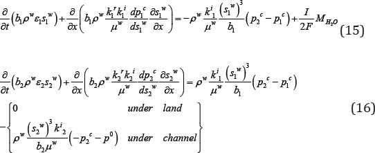
In order to build this new model for water transport in two thin layers, some assumptions were taken; The GDL is assumed to be at a constant pressure and the problem under study is generalized as isothermal immiscible air-water flow, and will be extended for the non-isothermal case. The mass conservation equations of liquid water in the two layers are given by Qin & Hassanizadeh [28]:
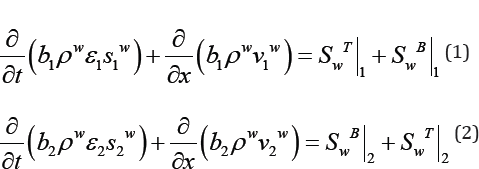
where the subscripts 1 and 2 denote the MPL and GDL, respectively, b is the layer thickness,
v is the superficial in-plane water velocity, x is the in-plane direction, is the water input through the bottom of MPL which is pre-specified, accounts for the water transport out of the GDL through its top, and the water exchange through the MPL-GDL
interface is taken into account by
is the water input through the bottom of MPL which is pre-specified, accounts for the water transport out of the GDL through its top, and the water exchange through the MPL-GDL
interface is taken into account by 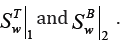
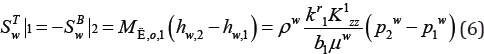
Recently, Kaffel A in 2017 have derived a new model for the mass exchange between neighboring layers, through the vertical integration over the layer. h was defined as the piezometric head in the layer i:
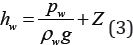
Where Pω is the intrinsic average of the pressure of water phase, Z is the vertical coordinate of the elevation head associated to the lab frame R0 =ez .g is the acceleration due to gravity. Note that the quotient  denotes the pressure head. The layer- layer mass exchange of water may be defined as:
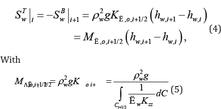
 is the mobility of water phase in the layer i, which
is the ratio of relative permeability to water viscosity. Kzz is the permeability component in the z-direction.
is the mobility of water phase in the layer i, which
is the ratio of relative permeability to water viscosity. Kzz is the permeability component in the z-direction.
Since we start the study with two 1D domains, the mass exchange terms of water between the two layers can be given as:
The relative permeability, same for the Richard model and reduced continua model, is assumed to be a function of saturation:
kr=(sw)3
According to the thermodynamic, the full form of fluid motion equation in each thin layer may be given as (the motion is in the inplane direction, and uniform layer thickness is assumed):
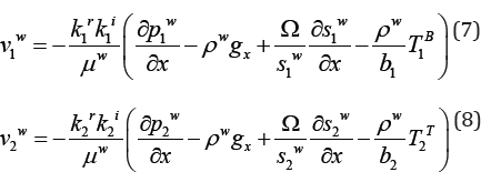
Where Ω is the wettability potential, TB1is the in-plane stress input from the bottom of MPL, and T2T is the in-plane stress input from the top of GDL. Both are zero in the present case studies.
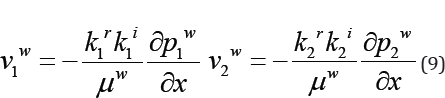
After neglecting the gravity effect and non-Darcian terms from the full form of fluid motion equation in each thin layer a 1D two- phase Darcy equations for water transport were obtained:
The boundary conditions were assumed to be as follow:
For the water input to the bottom of MPL, we assume that -similar to the boundary condition of the Richards model and to the reduced continua model- on the cathode side the back diffused water through the membrane just balances the water from the EOD:

Where p^0the water pressure in the GC. If there is no liquid water in the GC, we setp0 to zero in correspondence with the upper boundary condition for the Richards model and the reduced continua model where the saturation in the GC was assumed to be zero [19]. That can be justified by the fact that high gas flow rates in the GC will remove emerging liquid water droplets effectively. Finally, under the land areas, no water can go out of the GDL. Therefore,  is set to zero. The two phase pressures are linked by the macroscopic capillary pressure as: Pα - PW = PC
Where Pα is the air pressure, and Pc is the capillary pressure which is traditionally assumed to be a function of water saturation only. Because a constant air pressure is assumed, we can write:
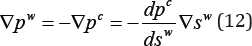
The capillary pressure can be given by the Leveret function J which depends on the water saturation [29,30]:
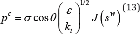
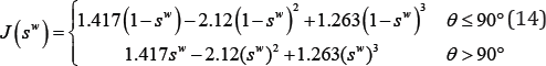
Here, σ is theair-water surface tension, and θ is the contact angle of the porous medium.
Combining those equations results in the following two equations which can be solved for the average saturations s_1^w and s_2^w:
Boundary conditions
The boundary conditions for our model are; no-flux conditions imposed at the two ends in the x direction. The boundary conditions at the bottom of MPL and the top of GDL appear as the source and sink terms in the governing equations (15) and (16), respectively.
Some numerical results and discussion
Unlike the reduced continua model derived by Hassanizadeh et al. [19], in which they considered an empirical model for the mass exchange term, our model is based on a new explicit accurate model obtained through averaging over the thickness of the layer, so we expect the results approach to the macroscopic averaged model results.
We just started our tests for the new model described above using COMSOL Multiphysics. The same values of various geometric, physical and operating parameters in [19] were used. The modeling domain is the same used in the reduced continua model simulation (Figure 2). In all simulations, for the reduced continua, the value of the parameter d was set equal to 2 and a perfect contact between the two layers was assumed (i.e. m=1).
The Simulations were performed for various cases and for different parameters. The values of geometric, physical and operating parameters used in the simulation are listed in Table 1.
Table 1: Geometric, physical, and operating parameters.

The modeling domain for the reduced continua approach is the one shown in Figure 2, a 2000|im wide domain where the two layers have the same contact angle of 110° and both are hydrophobic. Based on the assumption that there is no liquid water in the GC, pA0 was set to zero. For the simulation, the mathematical model was used by specifying partial differential equations (PDEs) by acting on the coefficients in general template equations in order to define the problem’s equations.
Results and discussion
In order to validate our model we had to compare our results with results of the reduced continua model. We set the parameters that match with those used in. The numerical results, shown in Figure 3, 4a, 4b and 5, agree very well with those of Hassanizedeh et al. [19] results. The steady-state water distributions in the MPL and GDL obtained from the reduced continua model and the new model are shown in Figure 3. In the GDL, the reduced continua model predicts less water saturation, especially under the channel area. In the MPL, the new model predicts lower water saturation under the channel area but slightly higher saturation in the under land areas.
Figure 3: Steady-state water saturation distributions along the in-plane direction obtained from the new model and the reduced continua model in MPL and GDL.

Transient simulations results with the two models are presented in Figure 4 & 5. The temporal evolution of averaged water content in the MPL and GDL is shown in Figure 4a & 4b. Our model predicts higher water content in the GDL especially under the channel area. We can clearly observe that the water content curves obtained from the new model have the same shape as the Richard model curve results but with less water content in each layer. Figure 5 presents the temporal evolution of water pressure in MPL and GDL. As it was found in previous research [29-31], averaged pressure is higher inside the MPL than inside the GDL, due to smaller pore size and enhanced hydrophobicity, making the MPL less prone to flooding. The MPL is more like a pressure valve with a two-fold function: pushing the water to the membrane side to effectively hydrate the membrane, and providing a pressure buildup necessary to expel the water through the GDL pores into the cathode flow channels. The new model shows higher water pressure in GDL and quite similar steady-state value in the MPL. This results in lower pressure difference between the two layers.
Figure 4: Temporal evolution of water contents obtained from the new model and the reduced continua averaged over the channel area and two land areas (a) in MPL, (b) in GDL.

Figure 5: Temporal evolution of average water pressures ob-tained from the new model and the reduced continua in the GDL and in the MPL.

Sensitivity studies using the new model
The effects of both the GDL and the MPL, on water flooding are very complex, depending on the interactions of several properties (porosity, morphology, thickness and the PTFE content) and the interaction between the two layers and the flow fields of a PEM fuel cell [32].
Figure 6: Effect of the MPL thickness on the steady-state water distributions in the MP Land the GDL.

In accordance with the new model, larger MPL thickness would reduce the mass exchange between the two layers since with larger layer its capability to hold liquid water increases. Figure 6 shows that increasing the MPL provides more storage for liquid water inside it and the water saturation increases. But has no influence on the water saturation in the GDL.
Figure 7: Effect of the GDL thickness on the steady-state water distributions in the MPL and the GDL.

Manufacturing methods and materials used can significantly affect the water management characteristics of the GDL and the performance of the cell in which it is placed [33,34]. Figure 7 presents the influence of the GDL thickness on the steady-state water distributions. It shows that the water saturation in the GDL; under the land areas, decreases with the increases of the GDL thickness and it increases under the channel area. In the MPL, the same thing happens. With increase in GDL thickness, it can hold more liquid water inside it.
An investigation on the influence of GDL permeability on the steady-state water distributions in the MPL and GDL was also conducted. When varying the GDL permeability, Figure 8 shows that with higher permeability lower water saturation was found in both layers especially under the land areas. This is explained by the fact that higher in-plane permeability of the GDL enhances the transport of accumulated water into the channel area by providing less resistance for the liquid water to flow out.
Figure 8: Effect of the GDL permeability on the steady-state water distribution in the MPL and the GDL.

Conclusions and Perspectives
Finding a suitable equilibrium between membrane drying and flooding is critical for ensuring a better performance of PEMFCs. Therefore, understanding the water transport mechanism in PEMs is a key issue for avoiding cathode flooding and membrane dehydration it also serves as a guide for material optimization and development of the PEMFC.
In this work, we have successfully developed a new model based on the explicit closure model of the mass. We have compared water distribution obtained from the new model and the reduced continua model. This comparison proved the validity of our new model and showed a better modeling of water content in both layers. With the new model we studied the effect of structural and physical properties of the gas diffusion layer (GDL) and the micro porous layer (MPL) with emphasis on liquid water saturation within both layers. The change in permeability, contact angle and thickness of each of the layers has been examined and its influence on liquid saturation within the layers has been discussed. The results show that the transport within the porous layers is mainly governed by the GDL properties. This model will be used and extended later to include the thermal effects.
In the future work, we will try to extend our new model and focus on considering the phase change and electrochemical reactions in the CL and add it to our model. The rates of species mass exchange and heat exchange between neighboring layers will also be parameterized. A study of the effect of the CL on water transport and its sensitivity to different material properties such as its thickness, permeability, porosity and wettability will provide a better understanding of the fundamental processes of water management and flooding. We will be able to model heat transfer in the PEMFC and its effect on the water flooding by using the above model with convenient assumptions.
The temperature distribution in fuel cells is generally expected to be non uniform because of heat generation. This non uniformity is embodied in distributions not only across fuel cells, but also on the in-plane direction of components, eg. the non uniform temperature distribution on the membrane presented by [35]. The temperature is expected to increase from the anode to the membrane and then decrease from the membrane to the cathode. The temperature profile is almost linear at the anode and cathode sides, mainly because of heat conduction, and the temperature in the membrane is nonlinear because of Joule heat and the latent heat of water phase change [36-38]. Using the new model we will reformulate the macroscale governing equations by employing the averaging-thermodynamic approach and defining an REV for each layer. This study will provide better information about temperature distribution in the fuel cell and will give us a better idea about water transport since temperature will determine the rates of phase change and the water condensation and evaporation.
References
- Qin CZ, Hassanizadeh SM (2015) A new approach to modelling water flooding in a polymer electrolyte fuel cell. International Journal of Hydrogen Energy 40(8): 3348-3358.
- Jiao K, Zhou B (2007) Innovative gas diffusion layers and their water removal characteristics in PEM fuel cell cathode. Journal of Power Sources 169(2): 296-314.
- Bao C, Ouyang M, Yi B (2006) Modeling and control of air stream and hydrogen flow with recirculation in a PEM fuel cell system-I. Control-oriented modeling. International Journal of Hydrogen Energy 31(13): 1879-1896.
- Bhattacharya PK (2015) Water flooding in the proton exchange membrane fuel cell. Directions 15(1).
- Li H, Tang Y, Wang Z, Shi Z, Wu S, et al. (2008) A review of water flooding issues in the proton exchange membrane fuel cell. Journal of Power Sources 178(1): 103-117.
- W He (2003) Two-phase flow and electrode flooding in PEM fuel cell electrodes, University of Kansas, USA.
- Becker J, Wieser C, Fell S, Steiner K (2011) A multi-scale approach to material modeling of fuel cell diffusion media. International Journal of Heat and Mass Transfer 54(7): 1360-1368.
- Yi JS, Yang JD, King C (2004) Water management along the flow channels of PEM fuel cells. AIChE journal 50(10): 2594-2603.
- Wilkinson DP, Voss HH, Prater K (1994) Water management and stack design for solid polymer fuel cells. Journal of Power Sources 49(1-3): 117-127.
- St-Pierre J, Wilkinsor DP, Knights S, Bos ML (2000) Relationships between water management, contamination and lifetime degradation in PEFC. Journal of New Materials for Electrochemical Systems 3(2): 99106.
- Yang XG, Burke N, Wang CY, Tajiri K, Shinohara K (2005) Simultaneous measurements of species and current distributions in a PEFC under low-humidity operation. Journal of The Electrochemical Society 152(4): A759-A766.
- JH Nam, M Kaviany (2003) Int J Heat Mass Transfer 46: 4595-4611.
- Gaiselmann G, Froning D, Totzke C, Quick C, Manke I, et al. (2013) Stochastic 3D modeling of non-woven materials with wet-proofing agent. International Journal of Hydrogen Energy 38(20): 8448-8460.
- Becker J, Wieser C, Fell S, Steiner K, (2011) A multi-scale approach to material modeling of fuel cell diffusion media. International Journal of Heat and Mass Transfer 54(7-8): 1360-1368.
- Rebai M, Prat M (2009) Scale effect and two-phase flow in a thin hydrophobic porous layer. Application to water transport in gas diffusion layers of proton exchange membrane fuel cells. Journal of Power Sources 192(2): 534-543.
- Gostick JT, Ioannidis MA, Fowler MW, Pritzker MD (2007) Pore network modeling of fibrous gas diffusion layers for polymer electrolyte membrane fuel cells. Journal of Power Sources 173(1): 277-290.
- Zhou P, Wu CW (2010) Liquid water transport mechanism in the gas diffusion layer. Journal of Power Sources 195(5): 1408-1415.
- Niu XD, Munekata T, Hyodo SA, Suga K (2007) An investigation of water-gas transport processes in the gas-diffusion-layer of a PEM fuel cell by a multiphase multiple-relaxation-time lattice boltzmann model. Journal of Power Sources: 172(2): 542-552.
- Qin CZ, Hassanizadeh SM (2014) Multiphase flow through multilayers of thin porous media: General balance equations and constitutive relationships for a solid-gas-liquid three-phase system. International Journal of Heat and Mass Transfer 70: 693-708.
- Nguyen TV, White RE (1993) A water and heat management model for proton-exchange-membrane fuel cells. Journal of the Electrochemical Society 140(8): 2178-2186.
- Lange KJ, Sui PC, Djilali N (2011) Pore scale modeling of a proton exchange membrane fuel cell catalyst layer: Effects of water vapor and temperature. Journal of Power Sources 196(6): 3195-3203.
- Rowe A, Li X (2001) Mathematical modeling of proton exchange membrane fuel cells. Journal of Power Sources 102(1-2): 82-96.
- Wang L, Husar A, Zhou T, Liu H (2003) A parametric study of PEM fuel cell performances. International Journal of Hydrogen Energy 28(11): 1263-1272.
- Ju H, Meng H, Wang CY (2005) A single-phase, non-isothermal model for PEM fuel cells. International Journal of Heat and Mass Transfer 48(7): 1303-1315.
- Pasaogullari U, Mukherjee PP, Wang CY, Chen KS (2007) Anisotropic heat and water transport in a PEFC cathode gas diffusion layer. Journal of the Electrochemical Society 154(8): B823-B834.
- Pasaogullari U, Wang CY (2004) Two-phase transport and the role of micro-porous layer in polymer electrolyte fuel cells. Electrochimica Acta 49(25): 4359-4369.
- Zamel N, Li X (2010) Non-isothermal multi-phase modeling of PEM fuel cell cathode. International Journal of Energy Research 34(7): 568-584.
- Qin C, Rensink D, Fell S, Hassanizadeh SM (2012) Two-phase flow modeling for the cathode side of a polymer electrolyte fuel cell. Journal of Power Sources 197: 136-144.
- Holmström N, Ihonen J, Lundblad A, Lindbergh G (2007) The influence of the gas diffusion layer on water management in polymer electrolyte fuel cells. Fuel Cells 7(4): 306-313.
- Spernjak D, Prasad AK, Advani SG (2007) Experimental investigation of liquid water formation and transport in a transparent single-serpentine PEM fuel cell. Journal of Power Sources 170(2): 334-344.
- Pasaogullari U, Wang CY, Chen KS (2005) Two-phase transport in polymer electrolyte fuel cells with bilayer cathode gas diffusion media. Journal of the Electrochemical Society 152(8): A1574-A1582.
- Dohle H, Jung R, Kimiaie N, Mergel J, Müller M (2003) Interaction between the diffusion layer and the flow field of polymer electrolyte fuel cells-experiments and simulation studies. Journal of Power Sources 124(2): 371-384.
- Soler J, Hontanon E, Daza L (2003) Electrode permeability and flow-field configuration: influence on the performance of a PEMFC. Journal of Power Sources 118(1-2): 172-178.
- Hottinen T, Mikkola M, Mennola T, Lund P (2003) Titanium sinter as gas diffusion backing in PEMFC. Journal of Power Sources 118(1-2): 183188.
- Dadda B, Abboudi S, Ghezal A (2013) Transient two-dimensional model of heat and mass transfer in a PEM fuel cell membrane. International Journal of Hydrogen Energy 38(17): 7092-7101.
- Rowe A, Li X (2001) Mathematical modeling of proton exchange membrane fuel cells. Journal of Power Sources 102(1-2): 82-96.
- Berning T, Lu DM, Djilali N (2002) Three-dimensional computational analysis of transport phenomena in a PEM fuel cell. Journal of Power Sources 106(1-2): 284-294.
- Ramousse J, Deseure J, Lottin O, Didierjean S, Maillet D (2005) Modelling of heat, mass and charge transfer in a PEMFC single cell. Journal of Power Sources 145(2): 416-427.
© 2018 Ahmed Kaffel. This is an open access article distributed under the terms of the Creative Commons Attribution License , which permits unrestricted use, distribution, and build upon your work non-commercially.
Editor In Chief


.jpg)


Signup for Newsletter

Quick Links
 Editorial Board Registrations
 Submit your Article
 Refer a Friend
 Advertise With Us
Our Recent Edition

.jpg)


Top Editors


.jpg)


.bmp)
.jpg)
.png)
.jpg)


.jpg)


.png)

.png)


.png)


Financial Support

Sponsors

Latest e-Books

Latest Video

 a Creative Commons Attribution 4.0 International License. Based on a work at www.crimsonpublishers.com.
Best viewed in
a Creative Commons Attribution 4.0 International License. Based on a work at www.crimsonpublishers.com.
Best viewed in