
- About Us
- Information
-

The Author ensures that the research has been conducted responsibly and ethically with adherence to all relevant regulations. read more..
- For Authors
- For Reviewer
- Manuscript Guidelines
- Membership
- Publication Ethics
-
- Journals
- Reprints
- e-Books
- Videos
- Policies
- Contact Us
 COVID-19
- Submissions


Full Text
Novel Research in Sciences
Enriched Air Quality for Aircraft Electrical Environmental Control System with High Pressure Water Separator
Amir Zare Shahneh*
Centre of Aeronautics, Cranfield University, College Rd, Cranfield MK43 0AL, United Kingdom
*Corresponding author: Amir Zare Shahneh, Centre of Aeronautics, Cranfield University, College Rd, Cranfield MK43 0AL, United Kingdom
Submission: October 15, 2022;Published: October 19, 2022
.jpg)
Volume12 Issue2October, 2022
Abstract
The Electrical Environmental Control System (EECS) uses separate compressor and electric motor for compressed air instead of air extracting bleed air from engine. For a civilian aircraft carrying 200 passengers with temperature of 22 ℃, Relative Humidity (RH) of 15-18% and cruise altitude of 35,000 feet, the EECS is equipped with two independently electronically controlled three-wheel bootstrap Air Cooling Machine packs with high pressure water separator which are capable of supplying enough amount of fresh ventilation air of 1.3kg/s as per the design requirements. Cabin pressurisation systems are incorporated to maintain average cabin altitude of 5500 and not more than 7000ft. Air from the atmosphere is drawn by compressor operated by electronically controlled electrical motor. Before the air entering the main compressor, an inertial high pressure water separator is provided to separate the water or excess moisture. Water separator is by-passed once the aircraft attains higher altitude to avoid complete removal of moisture from air. The process promises a higher air quality for passengers and crew.
Keywords:Air conditioning pack; Pressurisation; ECS; High pressure water separator
Introduction
A civilian aircraft is designed to operate at cruise altitude of 35000 feet with passenger capacity of 209 seats with the cruse speed of 0.7 Mach. An Environmental Control System (ECS) is required to maintain passengers and crew in safe but also in comfortable conditions in terms of temperature, pressure, oxygen, humidity and other comfort parameters for the human well-being in long duration flights at all flight envelopes including high cruise altitudes. The cabin pressure should maintain between 5,500ft and 7000ft The EASA CS-25 [1] and Ashrae [2] standards are considered for designing the ECS system to meet all the design requirements. Packard-Le Pere LUSAC-11 [3] is the first aircraft designed by French to fly at the altitude above 30000ft. The cabin of this aircraft was not actually pressurised but supplied enriched oxygen into the sealed cockpit. Later American Lockheed XC-35 is the first aircraft to fly with pressurised cabin and controlled temperature. Till 1938, the method of maintaining pressure and temperature was restricted to only military aircraft. In 1938, Boeing 307 with radial piston engine is the first commercial aircraft designed with environmental control system. However, Boeing 787 [4] employs a dedicated compressor operated by electric motor instead of bleed air for its environmental control system.
Aircraft heat generation sources and fresh air
In aircraft, heat is generated from occupants, avionics equipment, and transfer through skin and radiation through the transparent surfaces. To avoid complexity in calculating heat load calculation, heat transfer is considered as steady state. Different types of heat loads which are considered for the designing EECS are: solar heating, avionic heat load, heat load due to occupants, kinetic skin heating and heat load from electrical and airframe systems. Heat balance equation can be derived as:

Where,
m : Rate of air flow into cabin (kg/s)
Cp : Specific heat of air at constant pressure (J/kgK)
U : Mean heat transfer coefficient of the wall (W/m2K)
A : Surface area of walls (m2)
Hs : Heat due to solar radiation (W)
Hp : Sensible heat from occupants (W)
He : Heat released by avionics components (W)
Ti : Temperature of the air entering the cabin (K)
Te : Temperature of the air leaving the cabin (K)
Ts : Aircraft skin temperature (K)
Tc : Inside cabin temperature (K), (which equal Te)
Fresh air is required for aircraft occupants. A minimum partial pressure of 6.5kPa of alveolar oxygen is available at 15,000ft, but should be increased to at least 14.3kPa. Concentration levels of CO2 in the air can be calculated by: [5]
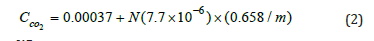
Where, CCO2: Concentration of carbon dioxide by volume m: rate of fresh air supplied to the cabin as per ventilation requirements in kg/s N=Number of occupants
With minimum air flow rate of 1.3kg/s and 209 occupants, concentration of CO2 is 0.0011845 which is equal to 1184.5PPM. Since the concentration of carbon dioxide is lower than the limit of 5000PPM, the amount of fresh air entering the cabin is sufficient to reduce the concentration of carbon dioxide. Hence, amount of carbon dioxide exhale by the occupants would not cause any effect on the occupant’s health. As aircraft cabin is maintained between 10-20% relative humidity, from the Figure 1, the comfort zone varies between 19 ℃ and 28 ℃. Comfort temperature zone during summer ranges from 24 ℃ to 28 ℃ and during winter, temperature ranges from 19 ℃ to 25 ℃. For the aircraft cabin, 22 ℃ is assumed to be the desired temperature considering the inlet temperature of air flow rate and power consumption for maintaining maximum temperatures.
Figure 1: ASHRAE comfort temperature zone for summer and winter [2].

Electrical environmental control system
Based on the cooling methods, ECS is categorized into three types: Ram air cooling, Air cycle cooling/refrigeration and vapor cycle refrigeration. Air cycle cooling is widely used in the aircraft for ECS. Air cooling cycle can be further subdivided into three types: Turbofan refrigeration system, Bootstrap refrigeration system and Electric ECS (EECS). The operation of EECS is similar to bootstrap refrigeration system except the source of high-pressure air. In EECS, air is drawn from the atmosphere and is compressed to high pressure by an electrically driven compressor instead of drawing high pressure bleed air from the engine as shown in the Figure 2.
Figure 2: Comparison of bleed and electrically powered ECS.

Power required for operating ECS is calculated for different flight conditions under various weather conditions. During take-off and descend, ECS will be operating with 50% of power (minimum ventilation requirement is considered) to reduce power extraction from engine. Power required during take-off is 56.1kW and 39.7kW during extreme hot weather and extreme cold weather conditions respectively. Power gradually increases from take-off power to the power required at cruise as 235kW.
Water separator
Ice is formed in the ACM turbine during expansion of air in the turbine. To avoid the formation of ice, ACM pack is equipped with a high-pressure water separator. The system consists of re-heater, condenser and water separator. Moisture in the air is condensed in the condenser and is collected in the water separator. The purpose of the re-heater is to heat the air entering the ACM turbine. The schematic layout of ECS gives the clear view of the system architecture and arrangement of components in the system. It helps in easy analysing the safety aspects and faults. Two independent identical three-wheel bootstrap ACM packs are employed in aircraft which ensure continuous supply of conditioned air into the cabin as per the design requirements. Operation of both the packs are similar. ACM pack consist of initial water separator, main compressor, pressure regulators, ozone converter, primary and auxiliary heat exchangers, by-pass valves, auxiliary compressor, turbine, re-heater, condenser, water separator shut off valves and non-return valves. Though water separator, electric motor and main compressor are not the part of ACM pack, author included these components in this section for better explanation.
Figure 3: Air machine pack layout and water separator.

Air from the atmosphere is drawn by compressor operated by electronically controlled electrical motor. Before the air entering the main compressor, a water separator (inertial type) is provided to separate the water (in case of rain) or excess moisture in air entering into the system. An electrical interface is provided to by-pass the water separator. Water separator is by-passed once the aircraft attains higher altitude to avoid complete removal of moisture from air. High pressure is then pass through the Pressure Regulating Valve (PRV) which regulates the pressure entering the ACM compressor. In case of excessive pressure, excess pressure is released to atmosphere to maintain design pressure in the ACM pack to avoid damage to the system components. As per the design requirements, Ozone is separated by the Ozone separator which is located after PRV. Before air entering the auxiliary compressor, it is cooled in the Primary Heat Exchanger (PHE). ACM compressor further compresses the air and fed to turbine through secondary heat exchanger and high-pressure water separator. Purpose of high-pressure water separator is to remove moisture from the air entering the ACM turbine. This avoids clogging or choking of turbine due to formation of ice during expansion of air. Arrangements of these components are shown in Figure 3.
Air leaving the turbine is used to cool the air in the condenser. The water condensed in the condenser is separated in the water separator and is discharged into the atmosphere along with the cooling ram air. Air is heated in the re-heater to increase the temperature of air entering the turbine. A temperature sensor is provided before the entrance of ACM turbine to sense the temperature of air entering into turbine. In case the temperature drops below designed value, it gives an electrical pulse/signal to the anti-icing valve. Anti-icing valve allows hot air to mix in the ACM mixing chamber (located at the exit of turbine) resulting in increasing the temperature of cooling air entering the condenser. This process increases the temperature of the air entering the reheater and eventually increases the temperature of the air entering the turbine. ACM packs are located under the floor between the heavy frames in the centre fuselage. Air intakes, located on the fuselage are chosen where the probability of entering exhaust gases of engine in the ECS is zero. Figure 4 shows the component of ECS including water separator.
Figure 4: Visual representation of ECS components including water separator.

Conclusion
The purpose of ECS is to maintain safe and comfortable temperature, pressure, humidity and quality of air inside the cabin at any altitude between ground and cruise. EECS is designed based on CS-25 and ASHRAE for the mass flow rate of 1.3kg/s fresh air during normal operation of both the ACM packs. During failure of one source, mass flow rate would be 0.627kg/s, cabin altitude maintained at 5500ft. Maximum amount of concentration of CO2 is calculated and found 1 184.5 PPM. Maximum limit of CO2 concentration is limited to 5000PPM. Regularly used Ozone converter is placed after the main compressor of both ACM packs. ECS will be designed to maintain 22 0C with relative humidity of 15-18%. Emergency oxygen will be provided for the occupants including crew at the time of cabin pressurization failure. Power required for operating ECS is calculated for different flight conditions under various weather conditions. Power required during take-off is 56.1kW and 39.7kW during extreme hot weather and extreme cold weather conditions respectively. Power gradually increases from take-off power to the power required at cruise (235kW). High pressure water separator is to remove moisture from the air entering the ACM turbine. This avoids clogging or choking of turbine due to formation of ice during expansion of air and better air quality.
References
- EASA (2008) Certification specifications for large aeroplanes. Europe, pp. 1-617.
- Ashrae (2004) Thermal environmental conditions for human occupancy. Ashrae, USA, pp. 1-30.
- https://en.wikipedia.org/wiki/Cabin_pressurization.
- Sinnett M (2007) 787 No-bleed systems: Saving fuel and enhancing operational efficiencies. Aero Quarterly, pp. 1-11.
- Hocking MB (2005) Air quality in airplane cabins and similar enclosed spaces. (4th), Springer, Germany.
© 2022 Amir Zare Shahneh. This is an open access article distributed under the terms of the Creative Commons Attribution License , which permits unrestricted use, distribution, and build upon your work non-commercially.
Editor In Chief


.jpg)


Signup for Newsletter

Quick Links
 Editorial Board Registrations
 Submit your Article
 Refer a Friend
 Advertise With Us
Our Recent Edition

.jpg)


Top Editors


.jpg)


.bmp)
.jpg)
.png)
.jpg)


.jpg)


.png)

.png)


.png)


Financial Support

Sponsors

Latest e-Books

Latest Video

 a Creative Commons Attribution 4.0 International License. Based on a work at www.crimsonpublishers.com.
Best viewed in
a Creative Commons Attribution 4.0 International License. Based on a work at www.crimsonpublishers.com.
Best viewed in