- Submissions

Full Text
Novel Research in Sciences
Choice of a Turbulence Model for Modeling Complex Flows in Rocket Engine Nozzles
Strelnikov G, Pryadko N*, Ihnatiev O and Ternova K
The Institute of Technical Mechanics of the National Academy of Sciences of Ukraine and the State Space Agency of Ukraine
*Corresponding author: Pryadko N, The Institute of Technical Mechanics of the National Academy of Sciences of Ukraine and the State Space Agency of Ukraine
Submission: March 18, 2022;Published: April 18, 2022
.jpg)
Volume10 Issue5April, 2022
Abstract
For simulation of turbulent flows the equations of the turbulent model are added to the general set of equations describing the flow in the Laval nozzle. There are several models of turbulence based on the use of Reynolds equations, which differ in approaches to the description of flow in the near-wall region, the number and physical meaning of additional unknown variables that determine the characteristics of turbulent flow. The flow in the nozzle with an obstacle is characterized by the appearance of developed separation zones with compaction jumps and significant gradients of velocity and pressure.
The calculations showed that the use of different turbulence models to the flow simulation in the classical Laval nozzle with the ANSYS software package does not significantly affect the flow characteristics. The perturbation mechanisms of the supersonic flow with a cylindrical solid obstacle mounted on the wall of the rocket engine nozzle in the throat and supersonic zones are studied. The results of using different turbulence models for perturbed flow are analyzed. It is shown that the TR-SST model, as a combination of the k-ε and k-ω models, is the most adequate to describe the perturbed flow in the nozzle of a rocket engine.
Keywords: Keywords: Eengine; Laval nozzle; Obstacle; Gas flow disturbance; Lateral force
Introduction
Computational Fluid Dynamics (CFD) is becoming an increasingly popular engineering tool. This is due to its qualities such as the formal simplicity of the problem statement and the independence of the methodology for solving it from the workflow of the node under study. The process of any CFD-calculation consists of five main stages-three stages of creating models: a geometric model; grid model of the computational zone; calculation model by supplementing the grid model with calculation conditions; and two calculation stages - search for a solution and presentation of calculation results.
Let us consider the features of calculating parameters and constructing a flow pattern in rocket engine nozzles based on the use of the ANSYS Fluent package, which allows modeling complex flows with disturbances in both two-dimensional and three-dimensional formulations.
The purpose of this work is to analyze the influence of turbulence models in the simulation of a disturbed gas flow in a rocket engine nozzle.
Material and Methods
For modeling turbulent flows, the equations of the turbulent model are added to the general set of equations describing the flow in the Laval nozzle. There are several turbulence models based on the use of the Reynolds equations, which differ in approaches to describing the flow in the near-wall region, the number and physical meaning of additional unknown variables that determine the characteristics of the turbulent flow. In all these models an additional term for turbulent eddy viscosity appears in the Navier-Stokes equations, but this term is calculated in different models in different ways. Let’s consider the main models and features of their application.
K-ε turbulence model
In the k-ε turbulence model two additional equations are written to calculate the turbulence kinetic energy k and the kinetic energy dissipation rate ε. The buffer layer is not modeled; wall functions are used to calculate the wall velocity. Due to its fast convergence and relatively low memory requirements, the k-ε model is very popular in solving technological problems. It is not very accurate for simulation flows with positive pressure gradient, jet flows and flows in a region with a highly curved geometry. This model is well suited for solving problems of external flow around bodies of complex geometric shape. For example, the k-ε model can be used to model flow near a bluff body.
K-ω turbulence model
The k-ω model is similar to k-ε one, but this model uses the equation for the specific dissipation rate of kinetic energy ω. This model belongs to the low Reynolds model, but it can also be used in conjunction with near-wall functions. It has a higher degree of nonlinearity, and therefore it converges to the solution worse than the standard k-ε model. In addition, it is quite sensitive to the initial approximation. The use of the k-ω model gives good results in those problems where the k-ε model is not accurate enough, for example, when modeling internal flows, flows along highly curved channels, separated and jet flows. A good example of the application of the k-ω model is the problem of fluid flow through a pipeline elbow.
SST- turbulence model
The SST model is a combination of k-ε and k-ω turbulence models: the equations of the k-ε model are used to calculate the flow in a free flow, and the equations of the k-ω model are used in the area near the walls. This is a low Reynolds model that has become a kind of standard for engineering applications. This model is devoid of some shortcomings of the original k-ω and k-ε models, although the requirements for mesh density remain.
Results and Discussion
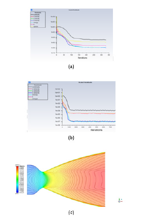
Laval nozzle calculations were carried out using various turbulence models: k-ε, k-ω and SST. The convergence results of the solution are presented below in Figure 1a & 1b.
The study of the flow pattern in the Laval nozzle showed that the chosen turbulence model does not affect the obtained results. The flow characteristics are the same in all three cases (Figure 1c).
Figure 1:Results of the convergence of the solution using turbulence models: k-ε (a) and k-ω (b), c) - flow pattern in the Laval nozzle using different turbulence models.

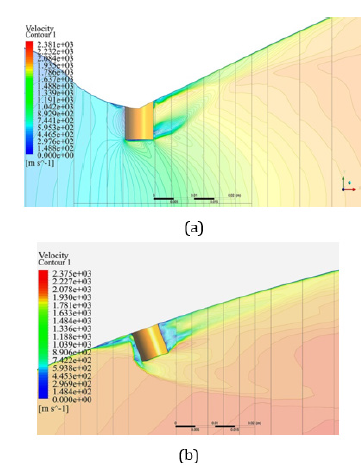
The flow in a nozzle with an obstacle is characterized by the appearance of developed separation zones with shock waves and significant velocity and pressure gradients. The authors have studied the mechanisms of supersonic flow perturbation with a cylindrical solid obstacle mounted on the wall of a rocket engine nozzle. Figure 2 shows the flow velocity field in the nozzle of a rocket engine with a solid obstacle (interceptor) in the throat and supersonic parts of the nozzle.
The calculation results were confirmed by comparing the results of integration of the perturbed pressure field with similar results obtained in studies [1-3] on models and full-scale rocket engines controlled by the perturbation of the supersonic flow by an obstacle on the wall.
The authors considered an inviscid gas model and 5 turbulence
models
A. inviscid flow model (invicid)
B. “k-ε” turbulence model (Realizable, Enhanced Wall Treatment).
C. “k-ω” turbulence model (SST modification).
D. Transition k-kl-ω model.
E. Transition SST model.
F. SAS model.
Let us refine the features of turbulence models for modeling disturbed flows in rocket nozzles.
Figure 2: Simulation results of the disturbed flow in the Laval nozzle caused with solid obstacles in the critical (a) and supersonic (b) sections of the nozzle.

The k-ε model is one of the first differential turbulence models proposed in [4]. Despite known limitations, it is widely used in engineering calculations. It is suitable for initial and parametric studies when comparing alternative designs. The shortcoming of the k-ε model in describing near-wall flows is the excessive generation of turbulence kinetic energy, which results in an underestimation of the size of separation zones, which can lead to significant errors in the design of aerodynamic objects. This model poorly predicts the properties of complex flows with strong pressure gradients, separation, and large curvature of streamlines.
The k-ω model demonstrates significant advantages [5]. Compared to the k-ε model, for simulation of near-wall flows, since no additional terms are required to be added to the equations for modeling the laminar-turbulent transition in the near-wall region. In addition, the k-ω model predicts well the separated flows. The disadvantage of the model is the strong dependence of the solution on the velocity values in the external flow [6]. Therefore, it is recommended to use the SST modification of the model [7]. Which is a combination of the k-ε and k-ω models.
SST works similarly to the standard k-ω model, but it does not have a strong dependence on external conditions for ω. It allows you to most accurately predict the gap. In addition, the model parameters are chosen in such a way that the model works well for near-wall separated flows. Therefore, it has become widespread in aerospace applications [7].
The SST k-ω model includes all refinements of the k-ω model and, in addition, takes into account turbulent shear stress transfer in determining turbulent viscosity. These features make the SST k-ω model [4] more accurate and reliable for a wide class of flows (for example, pressure gradient counterflows, airfoils, transonic shock waves) than the standard and k-ω models.
The Transition k-kl-ω model includes 3 transport equations for turbulent kinetic energy, laminar kinetic energy and inverse turbulent time scale ω and is mainly focused on correctly predicting the position of the laminar-turbulent transition.
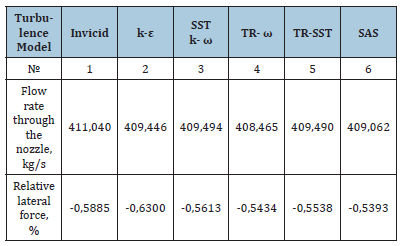
The SAS model combines the advantages of the Wilcox (k-ω) model and k-ε model, but still cannot correctly predict the onset and extent of flow separation from smooth surfaces. The main reason is that both models do not take into account the transfer of turbulent shear stress. This leads to an overestimation of the eddy viscosity prediction. Correct moving behavior can be obtained by using a limiter in the eddy viscosity formulation. The Table 1 shows the calculated values of the flow rate and the relative lateral force for a solid obstacle located in the supersonic zone.
Table 1: Flow characteristics for various turbulence models.

Comparison of the obtained results shows that, according to model 1, a non-viscous gas gives somewhat overestimated values of the flow rate through the nozzle, since it does not take into account the decrease in the effective area of the minimum section of the nozzle due to the boundary layer. The difference in consumption does not exceed 0.4%. Models 2-6 are in good agreement with each other, and the difference in consumption does not exceed 0.1%.
Calculations of the disturbed flow in the rocket nozzle showed that the inviscid gas model and k-ε models give overestimated values of the lateral force. In this case, the greatest discrepancy (up to 15%) is given by the k-ε model. This is due to the fact that for describing nearwall flows this model gives overestimated values of the kinetic turbulence energy which results in the size change of the separation zones. In addition, it poorly predicts the properties of complex flows with strong pressure gradients, separation, and large curvature of streamlines. The values of the lateral forces obtained for models 3-5 are in satisfactory agreement with each other. As shown by comparative estimates of the characteristics of the disturbed flow with the known results [2], the TR-SST model, as a combination of the k-ε and k-ω models, turned out to be the most adequately describing the disturbed flow in the rocket engine nozzle.
Conclusion
1. The calculation results of flow in the Laval nozzle showed
that the chosen turbulence model does not affect the obtained
results.
2. For simulation of disturbed flow in the nozzle the choice
of the turbulence model has a significant effect on the characteristics
of the disturbance and the lateral force magnitude. The
difference in the values of some perturbation parameters for
different models reaches 15%.
3. The most adequately describing the disturbed flow in the
rocket engine nozzle is the TR-SST model, as a combination of
the k-ε and k-ω models.
References
- Kovalenko ND (2003) Rocket engine as an executive body of the missile flight control system. ITM NAS and NSA of Ukraine, Dnepropetrovsk, Ukraine.
- Kovalenko ND, Strelnikov GA, Gora, Yu V, Grebenyuk LZ (1993) Gas dynamics of supersonic shortened nozzles. Naukova Dumka, Kiev, Ukraine.
- Ihnatiev O, Strelnikov G, Pryadko N, Vasiliv S, Ternova K (2021) Improving the gas flow control in rocket engines. Technical Mechanics 2: 60-77.
- Jones WP, launder BE (1972) The prediction of laminarization with a two-equation model of turbulence. International Journal of Heat and Mass Transfer 15(2): 301-314.
- Wilcox DC (1988) Reassessment of the scale determining equation for advanced turbulence models. AIAA Journal 26(11): 1299-1310.
- Menter FR (1992) Influence of freestream values on k-ω turbulence model predictions. AIAA journal 30(6): 1657-1659.
- Menter FR (1994) Two-equation eddy-viscosity turbulence models for engineering application. AIAA Journal 32(8): 1598-1605.
© 2022 Pryadko N. This is an open access article distributed under the terms of the Creative Commons Attribution License , which permits unrestricted use, distribution, and build upon your work non-commercially.
 a Creative Commons Attribution 4.0 International License. Based on a work at www.crimsonpublishers.com.
Best viewed in


.jpg)


 Editorial Board Registrations
 Submit your Article
 Refer a Friend
 Advertise With Us
.jpg)


.jpg)


.bmp)
.jpg)
.png)
.jpg)


.jpg)


.png)

.png)


.png)


