
- About Us
- Guidelines
-

The Author ensures that the research has been conducted responsibly and ethically with adherence to all relevant regulations. read more..
- For Authors
- For Reviewer
- Manuscript Guidelines
- Membership
-
- Journals
- Reprints
- e-Books
- Videos
- Indexing
- Contact Us
 COVID-19
- Submissions


Full Text
Novel Research in Sciences
Elastic-Plastic Multi-Scale Finite Element Analysis of Fracture Test on 304 Stainless Steel Compact Tension Specimen
Xing Ji* and Feng Zhu
School of Aerospace Engineering and Applied Mechanics, Tongji University, Shanghai 200092, China
*Corresponding author:Xing Ji, School of Aerospace Engineering and Applied Mechanics, Tongji University, Shanghai 200092, China
Submission: April 7, 2021;Published: April 20, 2021
.jpg)
Volume7 Issue3April, 2021
Abstract
The elastic-plastic multi-scale finite element method is formulated and applied to the analysis of the fracture test on compact tension specimen with 304 stainless steel. The calculation was carried out on ABAQUS. The elastic-plastic stress field near the crack tip, and the plastic zone are first determined in sufficient detail. The numerical results show that elastic-plastic stress singularity exists at the crack tip. Then, the critical updated Mises stress intensity factors of compact tension specimen and middlecrack tension specimen with 304 stainless steel are determined by using the fracture test results of the specimens. It is found that the magnitudes of these two critical updated Mises stress intensity factors are related to the specimen and differ greatly, they cannot be regarded as a characterization of the inherent fracture toughness of 304 stainless steel. This study shows that: the elastic-plastic multi-scale finite element method can offer the numerical results of the mechanical parameters of the singular stress field near the crack tip accurately enough, it provides an analytical basis for the development of fracture criteria of elastic-plastic fracture mechanics; combined with the fracture experiments of the cracked specimens, the elastic-plastic multi-scale finite element method provides an effective numerical analysis for the experimental verification of elastic-plastic fracture criterion.
Keywords: Multi-scale finite element method; Incremental theory of plasticity; Compact tension specimen; Elastic-plastic stress singularity; Fracture toughness
Introduction
For materials that fail under brittle conditions, the fracture criterion in Linear-Elastic Fracture Mechanics (LEFM) is widely accepted [1]. The asymptotic expression of the singular stress field of mode I crack tip obtained from theory of linear elasticity consists of the parameter KI and the angular distribution functions [2,3]. The parameter KI measures the intensity of singular stress field at the crack tip, and thus it is called as ‘‘stress intensity factor’’ of mode-I crack. When KI reaches its critical value KIC , brittle fracture occurs [4]. Thus, the single-parameter criterion based on stress intensity factor for brittle fracture has solid theoretical and experimental ground. For materials that exhibit significant plasticity prior to failure, various single-parameter criteria for elastic-plastic fracture have been proposed, such as J-integral [5-7], CTOD [8], CTOA [9], etc. It is still uncertain which is the most satisfactory criterion [10-12]. For more than half a century, efforts have been made to improve the elasticplastic fracture criterion [12]. The difficulty of analytical approach lies in the nonlinearity of plasticity and geometry, and the difficulty of numerical approach lies in the stress singularity at the crack tip. In contrast, the numerical approach is more feasible.
Early in the 1970s and 1980s, Rice et al. [13] first devoted to the development of elasticplastic finite element method, for the study of elastic-plastic fracture mechanics [13-17]. Thereafter, the finite element analysis of elastic-plastic deformation near the crack tip has been the focus of research [18-24]. Based on the elastic-plastic finite element analyses of compact tension specimen with ABAQUS, the CTOD estimation obtains improvements of nearly 25% over the existing formula [19]. However, in order to evaluate the reliability of the existing elastic-plastic fracture criteria more accurately, the finite element analysis technique for the elastic-plastic field near the crack tip has to be further improved. There are two issues that need special attention: 1. As approaching the crack tip, the accuracy of finite element analysis must be maintained; 2. Because the elastic-plastic deformation near the crack tip will reach a very large extent, it is necessary to mesh the crack tip finite elements appropriately to avoid the calculation interruption due to the excessive shape distortion of the crack tip elements.
Recent paper [25] proved that the multi-scale finite element method (i.e., the element sizes near the crack tip continuously transit from the nanometer scale to micrometer scale and millimeter scale) can accurately describe the elastic singular stress field near the crack tip, if the refined finite element mesh near the crack tip can well simulate the asymptotic expression of the crack tip field. As the results, the difference between the numerical and analytical results for the stress intensity factor is less than 1% [25]. In reference [26], The Multi-Scale Finite Element Method (MSFEM) is applied to the elastic-plastic crack problem, and a multi-scale finite element mesh model near the elastic-plastic crack tip is proposed. Numerical example shows that the multi-scale finite element method is a promising tool for solving the crack problems of large elastic-plastic deformation.
The present paper focused on the application of the elasticplastic multi-scale finite element method in Elastic-Plastic Fracture Mechanics (EPFM). The Elastic-Plastic Multi-Scale Finite Element Method (EPMSFEM) complemented with incremental theory of plasticity is formulated and applied to the analysis of the fracture test on compact tension specimen with 304 stainless steel (304- C(T)). The experimental curve of engineering stress vs engineering strain of 304 stainless steel is fitted by Ramberg-Osgood equation [11]. Based on the Ramberg Osgood equation, the numerical relationship between true stress and logarithmic plastic strain is obtained. The multi-scale finite element mesh near the crack tip of 304-C(T) is optimized. So that, even if the plastic deformation of crack tip elements is up to a large extent, the whole calculation can be completed in one loading step without re-meshing. On this basis, the elastic-plastic stress field near the crack tip, and the plastic zone are first determined in sufficient detail. From the numerical results, it is seen that the crack tip field of 304-C(T) shows the characteristics of elastic-plastic stress singularity, even if the crack tip is in largescale yield. So, the updated Mises stress intensity factor can be calculated with the output data. Then, the critical updated Mises stress intensity factor of compact tension specimen and middlecrack tension specimen of 304 stainless steel are determined by using the fracture test results of the two kinds of specimens [11]. Because the magnitudes of these two critical updated Mises stress intensity factors are related to the specimen and differ greatly, they cannot be regarded as a characterization of the inherent fracture toughness of 304 stainless steel. The research in this paper shows that: the elastic-plastic multi-scale finite element method can offer the numerical results of the mechanical parameters of the singular stress field near the crack tip accurately enough, it provides an analytical basis for the development of fracture criteria of elasticplastic fracture mechanics; combined with the fracture experiments of the cracked specimens, the elastic-plastic multi-scale finite element method provides an effective numerical analysis for the experimental verification of elastic-plastic fracture criterion.
Fracture Test of Compact Tension Specimen with 304 Stainless Steel
In this section, the experimental results of the fracture test of 304-C(T) are taken from reference [11]. Reference [11] presents the results of an experimental and predictive round robin conducted by the American Society for Testing and Materials (ASTM) Task Group E24.06.02 on Application of Fracture Analysis Methods. The configuration of 304-C(T) is shown in Figure 1. Where W0 is specimen width, a0 is initial crack length. The specimen thickness is denoted with B. The dimensions and the experimental failure load f P of 304-C(T) are listed in Table 1. Average tensile properties of 304 stainless steel are listed in Table 2. Where E is modulus of elasticity, σys is yield stress of 0.2% offset, σu is ultimate tensile strength.
Figure 1: Compact tension specimen [11].

Table 1: Dimensions and experimental failure load of compact tension specimen with 304 stainless steel [11].

Table 2: Average tensile properties of 304 stainless steel [11].

In [11], the experimental engineering stress-strain curve of 304 stainless steel is fitted by the Ramberg-Osgood equation as
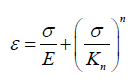 (1)
(1)
where σ and ε are engineering stress and engineering strain respectively. Kn and n are strain-hardening coefficient and power of strain-hardening respectively. Values of Kn and n of 304 stainless steel, are also given in Table 2.
Formulation of Elastic-Plastic Multi-Scale Finite Element
Incremental theory of plasticity
The Elastic-Plastic Multi-Scale Finite Element Analysis (EPMSFEA) is carried out on Abaqus [27]. The incremental theory of plasticity is adopted. Because of the large elastic-plastic deformation, the option “NLGEOM” is set at “on” to deal with geometric nonlinearity. The updated Lagrange format is used when NLGEOM is specified.
True stress vs Logarithmic plastic strain curve for 304 stainless steel
In order to conform to the incremental theory of plasticity,
the input data of plastic property of 304 stainless steel should be
expressed as true stress and logarithmic plastic strain.
In ABAQUS, true stress σ is defined as
σ =σ (1+ε ) (2)
Logarithmic plastic strain εp is
εp=ln(1+εp) (3)
In which, according to Ramberg-Osgood equation of 304 stainless steel, Eq. (1),
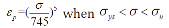 (4)
(4)
Using Eq. (2) to (4), the true stress-logarithmic plastic strain (σ −εp ) curve of 304 stainless steel can be obtained as shown in Figure 2. In the figure, the curve is composed of two segments. The segment (0 ≤ εp ≤ 0.34 ) is fitted with the experimental curve, and the segment (0.34 ≤ εp ≤ 4.4) is the extended segment determining by the Ramberg-Osgood equation. The point εp = 0.34 is corresponding to the ultimate strength σu of 304 stainless steel.
Figure 2: True stress vs logarithmic plastic strain curve for 304 stainless steel.

Nonlinear analysis
The failure load Pf of 304-C(T) is 47.8kN (Table 1). In order to prevent the plastic strain increment in each load increment excesses the allowed limit, the total load is divided into 1000 increments. At the end of each load increment, the node coordinates are updated to the current configuration and a new stiffness matrix is formed.
Element type
In EPMSFEA of 304-C(T), six-node triangular isoparametric element of plane strain (CPE6) is adopted for triangular elements, eight-node quadrilateral isoparametric element of plane strain (CPE8) is adopted for quadrilateral elements.
Finite element mesh refinement near the crack tip
In the mesh refining area near the crack tip, element sizes continuously transit from the nanometer scale to micrometer scale and millimeter scale, as showed in Figure 3. The crack tip elements (nano scale finite elements containing the crack tip) need to be shape-optimized to avoid the excessive distortion caused by the accumulated plastic deformation under large-scale yield condition. For 304-C(T), the core of the mesh refining area is a circular domain with the center at the crack tip. The radius of the core of the mesh refining area is r1=10xs (nm), s is the minimum size of the crack tip element. In the core, ten divisions are uniformly allocated along the crack surface, and five divisions are uniformly allocated along the ligament (Figure 3b). The 1st CTE at the left side of the crack tip is an isosceles triangle having a top angle of 120°. The 2nd and 3rd CTE lie on the right side of the crack tip. They are obtuse triangles, and the sum of their vertex angles at the crack tip is 60o. 4th CTE to 7th CTE are quadrilateral elements. They are a combination of two triangle elements. In our calculation, the minimum size of the crack tip element s is set as 100, 200, or 300nm. Out of the core, in the remaining mesh refining area, element sizes continuously transit from the nanometer scale to micrometer scale and millimeter scale. Outside the mesh refinement area, the stress changes moderately.
Figure 3: (a) Finite element mesh of compact tension specimen with 304 stainless steel, (b) Refining mesh model near the crack tip in the inner circle.

The proposed optimized crack tip element mesh Figure 3 has achieved good results. Even if the plastic deformation of the crack tip element is up to a large extent, the whole calculation can be completed in one loading step without re-meshing. The EPMSFEA results of the fracture test for 304-C(T) are given in the following section.
Results from Elastic-Plastic Multi-Scale Finite Element Analysis
The fracture test of 304-C(T) was analyzed with EPMSFEM. Pf is the failure load of the compact specimen. Set P be the current load acting on the specimen and define P’= P/Pf as the load ratio.
Plastic zone
Figure 4 shows the plastic zone of 304-C(T) with s = 300nm under different load ratios, P’= 0.1, to 1 (labeled in the drawing). The plastic zone of mode I plane strain exhibits a typical butterfly type.
Figure 4:Plastic zone of 304-C(T) with s=300nm.

Deformed shape of crack tip elements
Figure 5 depicts the deformed shape of the crack tip elements and their adjacent elements under different load ratios, P’=0.25, 0.5, 0.75, 1.0 (labeled in the drawing). The deformation of the 1st CTE has unique characteristics. As the load increases, the bottom edge of the 1st CTE rotates around the crack tip, and the element continues to elongate. After 1000 increments of loading, the bottom edge of 1st CTE turns a large angle around the crack tip, and the 120° top angle decreases to an acute angle, as showed in Figure 5. Therefore, the deformation of the 1st CTE is characterized by large displacement and large strain.
Figure 5: Deformed shape of crack tip elements of 304-C(T) with s=300.

Y-component of true stress and y-component of logarithmic plastic strain
Figure 6: Distribution of y-component of true stress of 304-C(T) with s=300nm.

Figures 6 & 7 describe the y-component of true stress σy and y-component of logarithmic plastic strain εpy of 304-C(T) with s=300nm along the ligament under different load ratios, P’= 0.25, 0.5, 0.75, 1.0, respectively. r denotes the initial distance from the crack tip.
Figure 7:Distribution of y-component of logarithmic plastic strain of 304-C(T) with s=300nm.

True mises stress and equivalent logarithmic plastic strain
Figures 8 & 9 describe true Mises stress and equivalent logarithmic plastic strain of 304-C(T) with s =300nm along ligament under different load ratios, P’= 0.25, 0.5, 0.75, 1.0, respectively. r denotes the initial distance from the crack tip.
Figure 8: Distribution of mises true stress of 304- C(T) with s=300nm.

Figure 9: Distribution of equivalent logarithmic plastic strain of 304-C(T) with s=300nm.

Mises Stress Intensity Factor and Singularity Index
In the elastic-plastic stress field near the crack tip of 304-C(T) specimen, Mises stress (σMises) may be chosen as the mechanical variable for the asymptotic expression. Figure 10 shows, σMises − r curves in logarithmic coordinates, when P’ = 0.25, 0.5, 0.75, 1.0 and s = 300, 200, 100nm. r denotes the initial distance from the crack tip. It is seen that the curve segments (the starting point r = 2snm and the end point in the interval of 0.0025mm ≤r≤0.01mm) given in Figure 10 can be approximated by straight lines. Therefore, they can be fitted by the following asymptotic expression,
Figure 10:σMises − r curves in logarithmic coordinates of 304-C(T) with s = 300, 200, 100nm.

σMise=(Kp)Ir -λp,r →0
where (Kp)I is mode I Mises stress intensity factor, λp is singularity index. (Kp)I and λp of 304-C(T) with s=300, 200, 100nm from EPMSFEA when P’= 0.25, 0.5, 0.75, 1.0 are calculated and given in Table 3.
Table 3: Values of engineering Mises stress intensity factor and singularity index of 304-C(T), (Kp)I and λp.

Elastic-Plastic Stress Singularity
The way to identify whether there is stress singularity at the crack tip by using the numerical results of finite element method is to see whether there is an asymptotic expression of negative exponent in the elastic-plastic stress field near the crack tip. According to Figure 10 and the asymptotic expression Eq. (5), it is seen that the crack tip field of 304-C(T) shows the characteristics of elastic-plastic stress singularity, even if the crack tip is in largescale yield.
Updated Mises Stress Intensity Factor and Associated Singularity Index
For the crack tip in large elastic-plastic deformation, it is appropriate to use r instead r in Eq. 5. r denotes the current distance from the crack tip (updated lagrangian coordinate). Figure 11 shows the σMises − r curves in logarithmic coordinates, when P’ = 0.25, 0.5, 0.75, 1.0 and s = 300, 200, 100nm, respectively. It is seen that the curve segments given in Figure 11 can be approximated by straight lines.
Figure 11:σMises − r curves in logarithmic coordinates of 304-C(T) with s=300, 200, 100nm.

Then, the asymptotic expression is written as following,
σMises = (Kp)Ir -λp,r →0()6
Kn and λp are defined as updated Mises stress intensity factor and corresponding singularity index respectively. (Kp)I and λp of 304-C(T) with s=300, 200, 100nm under P’= 0.25, 0.5, 0.75, 1.0 are calculated and given in Table 4. Therefore, (Kp)I also measures the intensity of the elastic-plastic field near the crack tip of 304-C(T).
Table 4:Values of updated Mises stress intensity factor and associated singularity index, (Kp)I and λp , of 304-C(T).

Updated Mises stress intensity factor-based elasticplastic fracture criterion
Because the updated Mises stress intensity factor characterizes the strength of the elastic-plastic singular stress field near the crack tip of 304-C(T), it can be used as the mechanical parameter for the fracture criterion. Therefore, following the establishment of fracture criterion of linear elastic fracture mechanics, a single parameter elastic-plastic fracture criterion can be established according to the modified Mises stress intensity factor.
(Kp)I=(Kp)IC (7)
where, (Kp)IC is the mode I critical updated Mises stress intensity factor. According to the results given in Table 5, When P’=1.0, the value of (Kp)IC = (Kp)ICCT . The critical updated Mises stress intensity factor of 304-C(T) with s=300, 200, 100nm is determined by tests as 47.70, 47.56 and 47.86 MPa mmλp, correspondingly. The validity of the elastic-plastic fracture criterion based on updated Mises stress intensity factor must be verified by the experimental results of other 304 stainless steel specimens.
Table 5: Dimensions and experimental failure load of middle- crack tension specimen with 304 stainless steel [11].

Critical Updated Mises Stress Intensity Factor of Middle- Crack Tension Specimens with 304 Stainless Steel
The fracture experiment of middle-crack tension specimens with 304 stainless steel (304-MT) is reported in [11]. Figure 12 shows the configuration of the specimen. The dimensions of 304-MT are listed in Table 5. The experimental failure load of the specimen, Pf= 458kN, is also given in Table 6. The fracture test of 304-MT was analyzed with EPMSFEM. Figure 13 shows the σMises -r curve in logarithmic coordinates of 304-MT with s =300nm, under P’=0.25, 0.5, 0.75, 0.9 respectively.
Figure 12: Middle-crack tension specimen (from [11]).

Figure 13: σMises -r curves in logarithmic coordinates of 304-MT specimen with s =300nm.

Table 6:Updated mises stress intensity factor (Kp)I and associated singularity index, λp , of 304-MT.

It is seen that the curve segments given in Figure 13 can be approximated by straight lines. Therefore, the asymptotic expression (6) is also applicable to the crack tip field of 304-CM. (Kp)I and λp of 304-CM with s=300nm when P’ = 0.25, 0.5, 0.75, 0.9 are calculated and given in Table 6. When P’ = 1.0, the value of (Kp)IC is obtained by extrapolation. From Table 6, the critical updated Mises stress intensity factor of 304-MT with s =300, nm is determined as 316.44 MPa mmλp
Experimental Verification of the Elastic-Plastic Fracture Criterion Based on Updated Mises Stress Intensity Factor
From Tables 4 & 6,
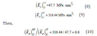
The critical updated stress intensity factor of 304-MT is 6.6 times of that of 304-C(T). The magnitudes of these two critical updated Mises stress intensity factors are related to the specimen and differ greatly. The difference between (Kp)ICMT and (Kp)ICCT cannot be neglected. Therefore, the critical updated Mises stress intensity factors of 304-MT, (Kp)ICMT , and 304-C(T), (Kp)ICCT, both cannot be considered as the inherent fracture toughness of 304 stainless steel. For 304 stainless steel, the elastic-plastic fracture criterion based on modified Mises stress intensity factor is not acceptable, because it has not been verified by the experiments. To establish the elasticplastic fracture criterion for materials such as 304 stainless steel, further study is necessary.
Conclusion
The research in this paper shows that: the elastic-plastic multi-scale finite element method can offer the numerical results of the mechanical parameters of the singular stress field near the crack tip accurately enough, it provides an analytical basis for the development of fracture criteria of elastic-plastic fracture mechanics; combined with the fracture experiments of the cracked specimens, the elastic-plastic multi-scale finite element method provides an effective numerical analysis for the experimental verification of elastic-plastic fracture criterion.
References
- Anderson TL (2005) Fracture mechanics. (3rd edn), Fundamentals and Applications. CRC Press, Boca Raton, USA.
- Irwin GR (1957) Analysis of stresses and strains near the end of a crack traversing a plate. J Appl Mech 24: 361-364.
- Williams ML, Calif P (1957) On the stress distribution at the base of a stationary crack. J Appl Mech 24: 109-114.
- Brown FW, Srawley JE (1966) Plane strain crack toughness testing of high strength metallic materials. ASTM STP 410: 12.
- Rice JR, Rosengren GF (1968) Plane strain deformation near a crack tip in a power-law hardening material. J Mech Phys Solids 16(1): 1-12.
- Hutchinson JW (1968) Singular behavior at the end of a tensile crack tip in a hardening material. J Mech Phys Solids 16(1): 13-31.
- Rice JR (1968) A path independent integral and the approximate analysis of strain concentration by notches and cracks. J Appl Mech 35(2): 379-386.
- Wells AA (1963) Application of fracture mechanics at and beyond general yielding. Br Weld J 10: 563-570.
- Kanninen MF, Rybicki EF, Stonesifer RB, Broek D, Rosenfield A, et al. (1979) Elastic-plastic fracture mechanics for two-dimensional stable crack growth and instability problems. ASTM STP668, pp. 121-150.
- Druce SG, Eyre BL (1979) A critical assessment of elasto-plastic fracture mechanics. Journal of Nuclear Materials 80(1): I- 12.
- Newman JC (1985) An evaluation of fracture analysis methods. ASTM STP896, pp. 5-96.
- Zhu XK, Joyce JA (2012) Review of fracture toughness (G, K, J, CTOD, CTOA) testing and standardization. Engineering Fracture Mechanics 85: 1-46.
- Hibbitt HD, Marcal PV, Rice JR (1970) A finite element formulation for problems of large strain and large displacement. International Journal of Solids and Structures 6(8): 1069-1086.
- Levy N, Marcal PV, Ostergren WJ, Rice JR (1971) Small scale yielding near a crack in plane strain: a finite element analysis. International Journal of Fracture Mechanics 7: 143-156.
- Nagtegaal JC, Parks DM, Rice JR (1974) On numerically accurate finite element solutions in the fully plastic range. Computer Methods in Applied Mechanics and Engineering 4(2): 153-177.
- Meeking RM, Rice JR (1975) Finite-element formulations for problems of large elastic-plastic deformation. International Journal of Solids and Structures 11(5): 601-616.
- Rice JR, McMeeking RM, Parks DM, Sorensen EP (1979) Recent finite element studies in plasticity and fracture mechanics. In: KS Pister (Ed.), Computer Methods in Applied Mechanics and Engineering, 17/18. North-Holland Publishing, 2: 411-442.
- Ma F, Kuang ZB (1994) Elastic-plastic fracture analysis of finite bodies-I. Description of the stress field. Eng Fract Mech 48(5): 727-737.
- Panontin TL, Makino A, Williams JF (2000) Crack tip opening displacement estimation formulae for C(T) specimens. Engng Fract Mech 67: 293-301.
- Wei Y (2002) Constraint effects on the elastic-plastic fracture behavior in strain gradient solids. Fatigue Fract Eng Mater Struct 25(5): 433-444.
- Kim YJ, Son B, Kim YJ (2004) Elastic-plastic finite element analysis for double-edge cracked tension (DE(T)) plates. Eng Fract Mech 71(7-8): 945-966.
- Tarafder M, Dash B, Swati D, Sivaprasad S, Das SK, et al. (2006) Modelling of crack tip blunting using finite element method. Project Completion Report, Report No. NML-GAP0088-03-2006.
- Zhang J, He XD, Suo B, Du SY (2008) Elastic-plastic finite element analysis of the effect of compressive loading on crack tip parameters and its impact on fatigue crack propagation rate. Eng Fract Mech 75(18): 5217-5228.
- Lamain LG (1983) Numerical analysis in EPFM. Proceedings of the 4th Advanced Seminar on Fracture Mechanics. Ispra, Italy, pp. 227-261.
- Ji X, Zhu F (2017) Determination of stress intensity factor with direct stress approach using finite element analysis. Acta Mech Sin 33: 879-885.
- Ji X, Zhu F (2019) Finite element simulation of elastoplastic field near crack tips and results for a central cracked plate of LE-LHP material under tension. Acta Mech Sin 35(4): 828-838.
- (2016) Abaqus/cae Usel’s guide. Modeling and Visualization.
© 2021 Xing Ji. This is an open access article distributed under the terms of the Creative Commons Attribution License , which permits unrestricted use, distribution, and build upon your work non-commercially.
Editor In Chief


.jpg)


Signup for Newsletter

Quick Links
 Editorial Board Registrations
 Submit your Article
 Refer a Friend
 Advertise With Us
Our Recent Edition

.jpg)


Top Editors


.jpg)


.bmp)
.jpg)
.png)
.jpg)


.png)

.png)


.png)


Financial Support

Sponsors

Latest e-Books

Latest Video

 a Creative Commons Attribution 4.0 International License. Based on a work at www.crimsonpublishers.com.
Best viewed in
a Creative Commons Attribution 4.0 International License. Based on a work at www.crimsonpublishers.com.
Best viewed in