- Submissions

Full Text
Medical & Surgical Ophthalmology Research
Design of a 40 MHz 128 Element CMUT Phased Array for Ophthalmic Anterior Segment Imaging
Rayyan Manwar and Sazzadur Chowdhury*
Electrical and Computer Engineering Department, University of Windsor, Canada
*Corresponding author: Sazzadur Chowdhury, Electrical and Computer Engineering Department, University of Windsor, Windsor, Ontario N9B 3P4, Canada
Submission: March 27, 2018;Published: April 10, 2018

ISSN 2578-0360 Volume2 Issue1
Abstract
A 40 MHz 128 channel linear phased array of capacitive micro machined ultrasonic transducers (CMUT) for ophthalmic anterior segment imaging application has been presented. The array has an aperture size of 2.41mm with an element pitch of 18.75mm. Each element is 10mm wide with an elevation depth of 5 mm. Each element of the array accommodates 264 small CMUT cells with a fill factor of 53.33%. Bisbenzocyclobutene (BCB), a low K polymer with excellent electrical, structural, and processing characteristics has been used to realize the CMUTs. The CMUTs were designed using a cross-verification platform comprised of Matlab™ based analytical and Intellisuite™ based 3-D electromechanical static and dynamic Finite Element Analysis (FEA). The analytical results for resonant frequency, diaphragm deflection profile and capacitance as a function of bias voltage were found to be in excellent agreement with a maximum deviation of 6.2% from the corresponding 3-D FEA results. Array analysis, focusing, and beamsteering in the pulse echo mode were performed using the Vantage128™ ultrasonic research platform from Verasonics™ to determine the imaging performance at a depth of 3mm and higher from the array surface. The Vantage128™ simulation results are in excellent agreement with published ophthalmic anterior segment imaging results that validates the design methodology.
Keywords: Phase array; Ophthalmic diagnostic imaging; Beam steering; Verasonics; Bisbenzocyclobutene; IntelliSuite; Sonometrics; Cmut; Polyvinylidene; Difluoride Transducer; Corneal Stroma; Specular Cornea; Piezoceramic; Glaucoma; penetration; polyvinylidene; emphasizing; corneal epithelium; ophthalmic; Matlab
Introduction
High-resolution ultrasonic imaging of delicate small tissues in eyes requires high frequency (>20MHz) ultrasonic transducers as higher frequency provides superior axial and lateral resolutions suitable for better diagnosis of small tissues. However, ultrasound waves at higher frequencies suffer higher attenuation that limits the penetration depth. As all the clinically important tissues in the anterior segment are located within a few millimeters from the surface of the eye, this imaging problem is an ideal candidate for high-frequency ultrasound to obtain high resolution images for better diagnosis [1-3]. In the early 1970s, several groups developed relatively simple reliable systems for ultrasound based routine clinical imaging of ophthalmic anterior segments. An ultrasound based manual B-scan method was developed and commercialized by Sonometrics Systems in New York for a broad variety of ocular and orbital diseases [4]. An instrument called ultrasonic bio microscope was reported in [4] where a 50-MHz polyvinylidene difluoride transducer and a sector scanner were used to achieve excellent definition of the anterior segment of an eye for diagnosis of glaucoma [4]. The Artemis system [4] uses 50- MHz transducers in an arc scan mode that maintains approximately normal angles of incidence over the entire surface of the specular cornea. This permits very high definition imaging over the entire anterior segment. In conjunction with digital signal processing, arc scans have provided highly detailed maps of the thicknesses and local radii of curvature of the 50-μm corneal epithelium and 500- μm corneal stroma. Such maps have helped to plan and evaluate corneal sculpting procedures such as LASIK [4].
The core technology of these high frequency ultrasound based imaging systems is the transducer. Typical commercially available high frequency ocular and orbital ultrasound imaging systems use transducers operating in the 20-80MHz frequency range [5-8]. These transducers scan the imaging area mechanically and suffer from small depth of field and lower frame rate that limits the image resolution near the geometrically fixed focus [6]. Current researchers are emphasizing on phased array technology to overcome this limitation. Unlike single element transducers, a phased array of transducer is capable of dynamic focusing and steering the beam electronically to achieve higher resolution image at minimum scan time. A phased array with larger aperture size and operated at shorter pulses can improve the axial resolution. On the other hand a narrow beam width can provide better lateral resolution. Grating lobes can be minimized by selecting an element pitch equal to or less than half of the wavelength of the center frequency [9].
Following [10], the thermal and mechanical indices for ophthalmic ultrasound imaging need to be less than or equal to 1.0 and 0.23, respectively. The derated spatial peak time average intensity for ophthalmic ultrasound imaging systems needs be less than or equal to 50m W/cm2 [10]. The high frequency transducer arrays as presented in [5-8] are either piezoceramic or other types of piezoelectric materials. However, achieving the required dimensions such as small element pitch and narrow kerf to avoid grating lobes and realize the small thickness of the active material as necessary for high frequency application is a tough challenge to fabricate ultrasonic transducers that rely on a piezoelectric transduction principle [9]. Acoustic impedance mismatch and relatively smaller electromechanical coupling coefficient are also dominant factors for degraded performance of the piezoelectric transducers [7].
The emerging Micro Electro Mechanical Systems (MEMS) based Capacitive Micromachined Ultrasonic Transducers (CMUT) have the potential to overcome the aforementioned limitations of the conventional piezoelectric transducers [11]. A CMUT is fabricated using processes similar to conventional VLSI technology [12]. Unlike the conventional piezoelectric principle based ultrasonic transducers, the CMUTs rely on electrostatic sensing and actuation methods for ultrasound generation and reception. These transducers offer superior methods of ultrasound based medical diagnostic imaging over their piezoelectric counterparts in terms of higher electromechanical coupling coefficient, wider fractional bandwidth, lower noise, higher thermal stability. They can be batch fabricated using advanced micro fabrication techniques with sub micrometer feature sizes and precisions that are necessary for high frequency application [13-16]. Kolo Medical Inc. has launched their first commercial CMUT array with a center frequency of 15 MHz for clinical applications [17].
A typical CMUT geometry is constructed to have a square, circular or hexagonal diaphragm that is supported on a fixed back plate by an insulating layer enclosing a small cavity filled with vacuum or air as shown in Figure 1. The structure functions as a variable capacitor where one of the electrodes (the diaphragm) is free to move or deform against the other (the back plate) to effect a change in capacitance.
Figure 1:A typical capacitive micromachined ultrasonic transducer (CMUT).
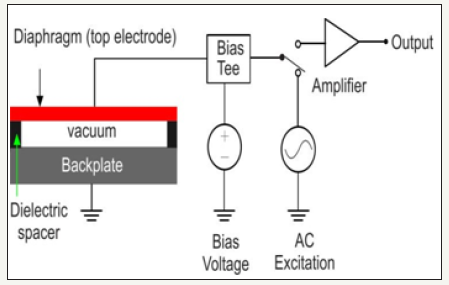
In the transmit mode, a DC bias voltage superimposed on an AC pulse of desired frequency range is applied across the CMUT electrodes to generate a time varying electrostatic force that causes the diaphragm to vibrate. This creates ultrasonic vibration in the surrounding medium. When the CMUT is exposed to an incident ultrasound wave, the sound pressure deforms the diaphragm (top electrode) towards the fixed bottom electrode. The resulting change in capacitance is converted to an electrical signal using a suitable microelectronic circuit. Detailed theoretical analysis of CMUT design, fabrication, and measured performances are available in [11-17]. Considering the target application of ophthalmic anterior segment imaging and the anticipated advantages of the emerging CMUTs and phased array operation as discussed, this paper present the design methodology of a CMUT based 128 element 40 MHz phased array.
Phased Array Design
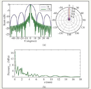
For the target ophthalmic application, 40MHz center frequency has been determined to be optimal considering the aperture size, depth of penetration, and fabrication constraints. Following the design approach as presented in [11,18-19], an aperture size of 2.41mm has been determined to be optimal for the target array as shown in Figure 2. To minimize the grating lobes, the element pitch size is chosen to be 18.75μm that equals λ/2 or half of the wavelength of the center frequency. The gap between two adjacent elements (kerf) has been decided to be 8.75μm considering the fabrication process constraints and mechanical strength of the dielectric spacers to support the diaphragms. Number of elements has been chosen to be 128 to improve lateral resolution. Matlab generated directivity pattern of the design array is shown in Figure 3a. For comparison purpose, directivity pattern of a 16 element array has also been shown. Detailed fabrication process of the array is available in [20].
Figure 2:A phased array geometry.
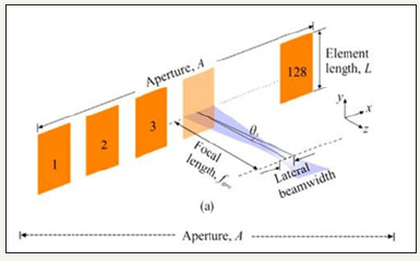
Figure 3 (a) Directivity comparison between 16 and 128 elements linear phased array with a pitch of 18.75 μm and (b) Near field pressure calculation of 128- elements array..
Following the Rayleigh criterion as expressed in (1) below:
EQUATION :

EQUATION:

The lateral resolution of the array as shown in (Figure 2) has been calculated to be 33.5μm. Following (2), the -3 dB angular response of a single element has been calculated to be ±42ᵒ
EQUATION:

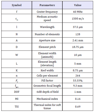
Figure 3b shows the generated acoustic pressure as a function of distance from the array surface as obtained from the MATLAB Transducer Array Calculation (TAC) Toolbox [21]. Following (Figure 3b) the maximum pressure at a distance of 2mm from the array surface is about 4MPa. This pressure corresponds to a peak time average intensity of 49.69mW/cm2 that is within the maximum attainable range for ophthalmic application [10]. Table 1 summarizes the key specifications of the designed array.
Table 1:Array specifications.
Beam Focusing Simulation
The pulse-echo and beam steering performance of designed array has been simulated in Vantage 128™ system from Verasonics™ [22], an industry standard imaging system for both piezoelectric and capacitive micro machined ultrasonic transducers.
In the pulse-echo mode, a simulated object model known as the ‘media point’ was placed at a distance of 100λ (3.75mm as maximum depth of anterior segment to avoid computational complexity) from the array top surface without apodization. Figure 4a shows the simulated echo as captured by the 64th array element in time domain after filtering (Butterworth) and averaging using the MATLAB signal processing toolbox. The frequency spectrum of the received signal as shown in Figure 3b shows a -6dB fractional bandwidth of 55%.
For the beam steering simulation in Vantage128™, two objects, viz. Object 1 and Object 2 were placed at a focal depth of 50λ (1.87mm that is considered as the minimum depth of the anterior segment from the array surface) and equally spaced apart from the center of the aperture by 1mm as shown in Figure 5. The beam was steered ±40ᵒ and the simulated return signal was received by elements 1, 64 and 128, respectively as shown in the Figure 5. As it is evident from Figure 5a, when steered to +40ᵒ, the strength of the echo received by the elements 1, 64, and 128 from Object 1 is much stronger as compared to the echo from object 2 received by the same elements. Some ringing due to reverberations is also visible. In Figure 5a, the dotted straight lines represent the echo signals received by elements 1, 64 and 128. Being the nearest element to object 1, element 1 received the echo signal 0.2 and 0.21 μs, respectively earlier as compared to element 64 and element 128 and shows higher amplitude compared to the other two elements (64 and 128) as shown in Figures 5b-5d respectively. Similarly, (Figures 5f-5h) show the echo signals received by the elements 1, 64, and 128 when the beam was steered -400. As it is evident from the figures, object 2 was identified by all the elements; however, element 128 being the nearest to the Object 2, received the echo earliest at 2.73 μs. Element 1 and 64 received the echo with a delay of 0.45 and 0.25 μs, respectively. An echo with 40% less strength was also noticeable that is due to the unwanted scattered echo from object 1 shown as curved line in Figure 5e. This analysis verifies that the designed CMUT array is capable of laterally distinguishing two objects apart by 1mm from each other even at one fifth of the geometric focal length using electronic beam steering and focusing.
Figure 4:(a) Vantage 128™ simulated pulse echo signal received by the 64th element at 40 MHz (no steering). (b) Spectra in frequency domain showing the-6dB fractional bandwidth as 55%.
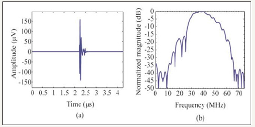
Figure 5:(a) Simulated echo signal from object 1 received by (b) element 1, (c) element 64, (d). element 128 at +40ᵒ steering angle, (e) echo signal from object 2 received by (f) element 1, (g) element 64 and (h) element 128 at -40ᵒ steering angle. The simulation was carried out in Vantage128™ from Verasonics™.

Design validation
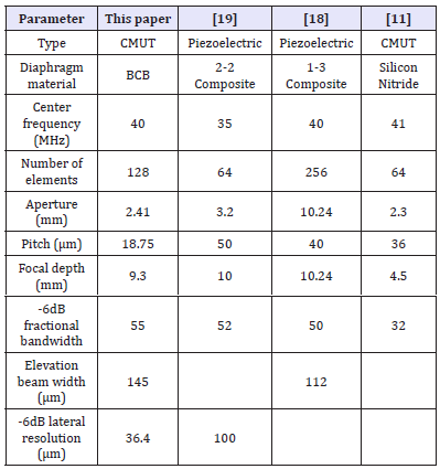
Table 2 presents a comparison of the key design specifications of the proposed CMUT array with similar array specifications published elsewhere [11,18-19]. The comparison establishes that the presented design is capable of providing a wider fractional bandwidth with a lower aperture size for an array with 128 elements to achieve sufficient focal length for ophthalmic diagnostic imaging application.
Table 2:Validation of the design methodology and analysis.
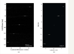
A set of performance data of the designed array obtained from phantom based B scan pulse-echo simulation in Vantage128™ from Verasonics™ was compared with phantom based experimental results published in [11] for an array with similar specifications. In the experiment in [11], a phantom with 4 glass fiber wire targets at the locations of the cornea, anterior chamber, and the iris of the anterior eye segment was used. A 41MHz silicon nitride based 64 elements CMUT linear array was experimentally operated in B-scan mode with a dynamic range of 40dB. The images obtained from the vantage128™ simulation for the designed array and experimentally obtained ones for the array reported in [11] for the phantom with same wire target specifications are shown in Figure 6. From the figure it is evident that the new CMUT array is capable of generating high-resolution images as compared to the array presented in [11] even at a depth of >3 mm where the iris is located.
Figure 6:B-scan of a four-wire phantom. (a) Experimental result from 41 MHz Si3N4 membrane based linear CMUT array [11], (b) Simulated result from 40 MHz BCB based linear phased array CMUT in Vantage128™.

Figure 7:(a) Vantage 128™ simulated pulse echo signal received by the 64th element at 40 MHz (no steering). (b) Spectra in frequency domain showing the-6dB fractional bandwidth as 55%.
The performance of the designed CMUT array was also compared to a 35 MHz piezo-composite ultrasound transducer array in B-scan mode based on the imaging of a five wire phantom as presented in [19]. These wires were located in such way to mimic the position of the rest of the part of the anterior segment. Synthetic aperture images from both the arrays are shown in Figure 7. Even though the piezo-composite transducer shows better quality images of the wires placed after 9mm due to higher axial resolution, the design CMUT array is capable of imaging the wires distinctly.
Conclusion
The design and validation of a 40MHz 128 element CMUT array for diagnostic imaging of the anterior segment of an eye has been presented. As the CMUTs offer superior electromechanical coupling coefficients and higher transduction efficiency, easy lower cost fabrication, the developed array is expected to provide superior diagnosis of anterior segment related medical conditions and diagnosis. The performance of the designed CMUT has been simulated using industry standard vantage128™ from Verasonics™ using standard medical phantoms and the results were compared to experimental results published elsewhere. Excellent agreement between the results validates the design methodology and the prospect of using high frequency CMUT arrays as an alternative to conventional piezoelectric transducer arrays.
Acknowledgements
This research has been supported by Natural Sciences and Engineering Research Council of Canada (NSERC)’s Discovery grant no RGPIN-2017-04574. The authors also greatly acknowledge the generous support provided by CMC Microsystems Canada, Angstrom Engineering, Kitchener, ON, and IntelliSense Software Corporation of Woburn, MA.
References
- Lockwood GR, Turnbull DH, Christopher DA, Foster FS (1996) Beyond 30 MHz: Applications of high frequency ultrasound imaging. IEEE Eng. Med. Biol 15(6): 60-71.
- Lewin PA (2007) High frequency biomedical and industrial ultrasound applications. in Proc of the International Congress on Ultrasonics, Vienna.
- Bantignies C, Mauchamp P, Dufait R, Levassort F, Mateo T, et al. (2011) 40 MHz piezo-composite linear array for medical imaging and integration in a high resolution system. Int Ultrason Symp 226-229.
- Lizzi F, Colema D (2004) History of Ophthalmic Ultrasound. Journal of ultrasound medicine 23: 1255-1266.
- Silverman RH (2009) High‐resolution ultrasound imaging of the eye – a review. Clinical Experiment Ophthalmology 37(1): 54-67
- Ketterling JA, Aristizábal O, Turnbull DH, Lizzi FL (2005) Design and fabrication of a 40-MHz annular array transducer. IEEE Trans Ultrason Ferroelect Freq Control 52(4): 672-681.
- Cannata JM, Ritter TA, Chen WH, SilvermanRH,Shung KK (2003) Design of efficient broadband single-element (20-80 MHz) ultrasonic transducers for medical imaging applications. IEEE Trans Ultrason Ferroelec Freq Control 50( 11): 1548-1557.
- Bezanson A, Adamson R, Bance M, JA Brown (2014) Fabrication and performance of a miniaturized 64-element high-frequency endoscopic phased array. IEEE Trans Ultrason Ferroelectr Freq Control 61(1): 33- 43.
- Szabo TL (2004) Diagnostic Ultrasound Imaging: Inside Out, Elsevier, USA.
- A Shaw, K Martin (2004) The acoustic output of diagnostic ultrasound scanner. In The Safe Use of Ultrasound in Medical Diagnosis.
- Yeh D, Oralkan O, Wygant I, Ergun A, Wong J et al. (2005) High resolution imaging with high-frequency 1-D linear CMUT arrays. IEEE Trans Ultrason Ferroelectr and Freq Control; 665-668.
- Rahman M, Hernandez J, Chowdhury S (2013) An improved analytical method to design CMUTs with square diaphragms. IEEE Trans Ultrason Ferroelectr Freq Control 60(4): 834-845.
- Ergun S, Yaralioglu G G, Oralkan O, Khuri-Yakub B T (2006) Techniques and Applications of Capacitive Micro machined Ultrasonic Transducers. MEMS/NEMS Handbook Techniques and Applications Design Methods, Volume 1, Ed. Cornelius, T. Leondes, 2006, Springer Science+Business Media, Inc; pp: 223-332.
- Savoia S, Caliano G, Pappalardo M (2012) A CMUT Probe for Medical Ultrasonography: From Microfabrication to System Integration. IEEE Transactions on Ultrasonics, Ferroelectrics and Frequency Control 59(6): 1127-1138.
- Khuri-Yakub BT, Oralkan Ö (2011) Capacitive Micro machined Ultrasonic Transducers for Medical Imaging and Therapy. Journal of Micromech and Microeng 21(5): 54004–54014.
- Unamuno A (2013) New Applications for Ultrasound Technology through CMUTs. Fraunhofer IPMS, Presentations at the joint event MNBS 2013 and EPoSS general assembly annual forum 2013/epossannual- forum-2013-26-september-2013.
- Zhao D, Zhuang S, Daigle R (2015) A commercialized high frequency CMUT probe for medical ultrasound imaging. In Proc IEEE Int Ultrason Symp pp: 1-4.
- Needles A, Foster FS, Brown JA, Lockwood GR (2006) 5C-3 A 40 MHz Linear Array based on a 1-3 Composite with Geometric Elevation Focusing. In Proc IEEE Ultrason Symp pp: 256-259.
- Cannata JM, Williams JA, Qifa Zhou, Ritter TA, KK Shung (2006) Development of a 35-MHz piezo-composite ultrasound array for medical imaging. In IEEE Trans on Ultrason Ferroelectr Freq Control 53(1): 224-236.
- Manwar R, Simpson T, Bakhtazad A, Chowdhury S (2017) Fabrication and Characterization of a High Frequency and High Coupling Coefficient CMUT M i c ro sys tem Te c h n o l o g i e s , S p r i n g e r V e r l a g 2 3 ( 1 0 ) : 4 9 6 5 - 4 9 7 7 .
- Kohout B (2012) Transducer Array Calculation (TAC) GUI-MATLAB. USCT, Karlsruhe Institute of Technology.
- Verasonics Inc. VANTAGE 128 Research Ultrasound Platform.
© 2018 Sazzadur Chowdhury. This is an open access article distributed under the terms of the Creative Commons Attribution License , which permits unrestricted use, distribution, and build upon your work non-commercially.
 a Creative Commons Attribution 4.0 International License. Based on a work at www.crimsonpublishers.com.
Best viewed in


.jpg)


 Editorial Board Registrations
 Submit your Article
 Refer a Friend
 Advertise With Us
.jpg)


.jpg)


.bmp)
.jpg)
.png)
.jpg)


.jpg)


.png)

.png)


.png)


