- Submissions

Full Text
Modern Research in Dentistry
One Step Optimisation (o.s.o) Process for Hard and Soft Tissue Augmentation in Single Implant Sites with the Poncho Lamina Technique: Clinical Protocol Description and Case Report
Tzovairis Alexander1*, Van Someren Brand Remco2 and Rossi Roberto3
1Private Practice, Brussels, Belgium
1Private Practice, Bleiswijk, The Netherlands
1Private Practice, Genova, Italy
*Corresponding author: Tzovairis Alexander, Private Practice, Brussels, Belgium, Rue des Aduatiques 25, 1040 Etterbeek, Belgium
Submission: February 21, 2022;Published: March 14, 2022

ISSN:2637-7764Volume7 Issue2
Abstract
Several techniques have been demonstrated in the bibliography for augmenting bone and soft tissue around dental implants. Adequate hard tissue volume and a correct, mimicking the nature, soft tissue configuration for the future prosthesis, assures stability and better prognosis of the implants in the long term. Nevertheless, achieving such an optimised result, is often related to a series of surgical invasive procedures that extend the length of treatment timeline and induce scar tissue formation. In this case report, a novel approach is introduced for simultaneous hard and soft tissue augmentation with the use of a well-documented cortical membrane for tissue augmentation adapted around a customise abutment for cervical profile generation. Two single implant site cases are presented. Each one is either related to a digital or analogue preparation of the customised abutment-Lamina membrane compound. Both cases showed optimised results in hard and soft tissue configuration after a healing period of at least 4 months. Further studies will be needed in the future to evaluate the efficacy of the proposed protocol in simultaneous hard and soft tissue augmentation during implant placement in edentulous sites.
Keywords: Lamina membrane; Customised abutments; Bone augmentation; Cervical profile; Dental implants
Introduction
The literature regarding implant supported restorations has well described the importance
of a proper emergence profile around dental implants [1] along with the preservation of a
good amount of keratinised tissue [2]. This condition:
1) provides an optimal site configuration for the future crown [3],
2) ensures a long-term stability for the patient’s implants [4].
Numerous techniques and approaches feature soft tissue augmentation and keratinised tissue addition to achieve such desired soft tissue optimisation in edentulous sites [5]. Nevertheless, an important factor that provides support for the augmented soft tissue is adequate hard tissue volume [6,7]. Current clinical efforts suggest the use of a 2 to 3 staged protocol to achieve both soft and hard tissue optimisation using customised abutments for cervical profile generation [8]. In numerous cases this means that the patient must undergo 2 to 3 surgeries and very often a grafting procedure to promote keratinised tissue especially in mandibular sites [9,10]. These 2 to 3 stage implant treatment protocols (Bone augmentation with or without simultaneous implant placement, implant uncovering with soft tissue management) [11,12] may induce scar tissue formation, less keratinised tissue preservation and longer implant treatments.
This paper proposes a new approach in soft and hard tissue augmentation for single implant sites performed through a One-Step Optimisation process (O.S.O.), with the use of a cortical membrane (Soft Lamina-Osteobiol by Tecnoss). This well documented resorbable membrane [13,14] is mounted on a customised abutment used to create an armonious emergence profile. A unique surgical protocol, adapted either for analogic or digital workflow, is presented along with two different cases.
Case Presentation
In this case report two patients were enrolled. The inclusion
criteria were:
A. Patients seeking implant treatment above 18 years of age,
B. Patients who signed an informed consent and accepted to
comply with the postoperative instructions and the follow up
planning,
C. Patients with a good oral hygiene and without presence of
periodontal disease (Plaque scores ≤25%, absence of pockets
during probing, BoP levels <25%),
D. Presence of keratinized mucosa with a minimum width of
4mm for edentulous, to be treated, sites.
The exclusion criteria were:
a) Patients presenting pathologies that affect bone metabolism
and wound healing,
b) Pregnancy and/or lactation during treatment and healing
period,
c) Smokers.
Case 1 - Digital Workflow
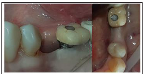
A 58-year-old female patient presented to our clinic seeking a solution to replace her lower left bicuspid. The patient was healthy, non-smoker and without periodontal disease. A pre-op Cone Beam Computed Tomography (CBCT) was performed on the lower third quadrant. CBCT revealed insufficient bone ridge width for placing an implant on site 35 (Figure 1) and a bone dehiscence on the neighbouring implant 36 (Tissue level Straumann) (Figure 2) due to aseptic bone loss. Bone density was qualified as type 3 [15] and the distance from the most coronal edge of the ridge to the canal of the Inferior alveolar nerve was sufficient to place a dental implant. The patient refused to replace the inadequate crown on the implant in site of 36. At the edentulous space of 35 clinical examination revealed 4mm of keratinised gingiva (Figure 3). There were no pockets or bleeding on probing on implant site 36.
Figure 1: Pre-op Cross Sectional image Site 35.
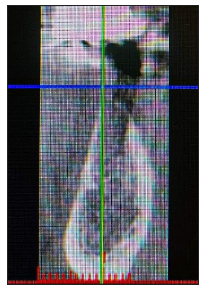
Figure 2: Pre-op Cross Sectional Image Site 36.
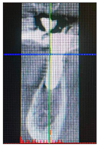
Figure 3: Pre-op Clinical images Site 35.
The patient was treated with the Poncho Lamina technique for a One Step Optimisation process regarding site 35. The treatment consisted in the use of an MIS V3 Implant (MIS Implants Technologies, BAR-LEV, Israel) along with Biogen 0.5 Xenograft (Biogen 0.5gr-Bioteck, Turin, Italy) mixed with liquid S-PRF (Process For PRF, Nice, France) and a Soft Lamina 25x25 membrane for lateral bone augmentation. The profile for cervical contour generation was fabricated with the help of the VPI Cervico system [16] (VP Innovato Holdings LTD, Cyprus) and was connected to the implant with the use of temporary cylinder adapted on a connect abutment (MIS Implants Technologies, BAR-LEV, Israel).
The workflow for this case had two main parts:
A. Lab fabrication of a customised profile unit for cervical
contour generation and a template for the surgeon to provide
an accurate shaping of the membrane that would be later
mounted on the abutment,
B. A surgical workflow for implant placement, bone grafting and
a correct adaptation of the soft tissues around the customised
abutment.
Lab digital workflow
Profile fabrication: A digital impression using an intraoral scanner device was initially taken (3Shape Trios) and an STL file was sent to the lab technician for further digital design of the profile and the template prior to the surgical procedure. The file was first imported into Exocad software. Then an appropriate to the site and interproximal space calibrated digital VPI Cervico tab was selected and imported into the software (Figure 4). A corresponding to the digital tab profile unit was designed after scanning the VPI Cervico mold with a Ceramill Map 400 scanning device (Amann Girrbach) and placed 3mm subgingival on the exocad model. The design was sent to the operator and following his approval, a groove of 1mm width and 0.5mm depth at marginal soft tissue level was created using Exocad tools (Figure 5). The profile was then printed with an Asiga 3D max printer using a Free print temp A2 resin, cleaned with isopropylic alcohol 99%, postcured using Otoflash G171 with Nitrogen and finally removed from its support structure and cleaned with a steamer.
Figure 4: Choosing the appropriate VPI Digital tab on Exocad model.
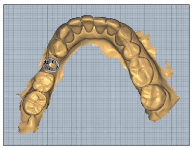
Figure 5:Retention groove creation on marginal tissue level.
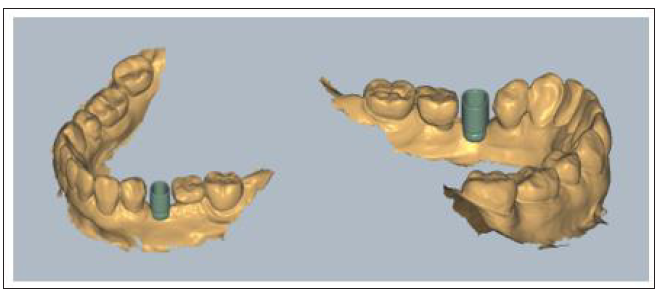
Template fabrication:The STL Profile unit was imported in the Blender 3D Software (www.blender.org) and a 45x45x3mm shape was created to serve as a template for the future shaping of the membrane. The profile unit and the template were aligned and then an intersection, using the unit, was made on the template which was later cut out. The thickness of the digital template was further increased and the STL file was printed to a Formlabs Form 2 3D printer (Formlabs) using Dental LT resin. The printed template was later cleaned with isopropylic alcohol 99% to remove excess resin, post cured in a BB Cure device removed from its support structure with a diamond bur and cleaned with a steamer. At the end of the procedure its thickness was reduced from 3 to 1mm with a dental wet trimmer.
Surgical workflow
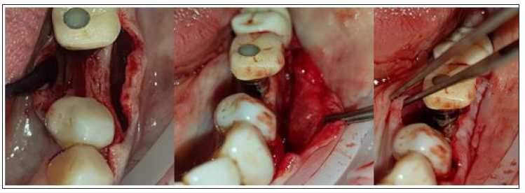
Following local anaesthesia (Articaine Hydrochloride/ Adrenaline) access to the edentulous ridge ridge was performed with a 15C Blade using intrasulcular buccal and lingual incisions from the distal area of tooth 33 till the distal aspect of tooth 37and a mid-crestal incision on edentulous site 35. The area of interdental papilla was carefully dissected in split thickness and 2 flaps (buccal-lingual) were meticulously elevated and further released with a periosteal incision at the buccal side and stretching of the mylohyoid muscle fibres using a periosteal elevator [17] (Figure 6).
Figure 6: Flap Elevation and release.
An alveolar ridge expansion protocol using Densah drills [18] (Versah LLC, Michigan, USA) followed on site 35 for the drilling preparation and an MIS V3 3.9 diameter and 10mm length implant (MIS Implants Technologies, BAR-LEV, Israel) was inserted sub-crestaly with a torque of 25 N.cm. A single unit abutment (Connect abutment 4mm diameter and 2mm height-MIS Implants Technologies, BAR-LEV, Israel) was connected to the implant with a final torque of 30N.cm (Figure 7).
Figure 7: Subcrestal Implant placement with Connect single unit.
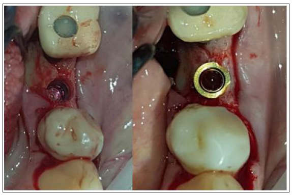
The connection between the lab fabricated profile unit and the single unit abutment was assured intraorally via an engaged temporary cylinder for connect abutment [19] (MIS Implants Technologies, BAR-LEV, Israel) and flow composite for bonding. The customised abutment was further polished and refined extra-orally.
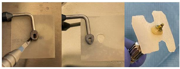
After the site preparation and implant placement a cortical lamina membrane (Soft Lamina 25x25mm- Osteobiol by Tecnoss SRL, Turin, Italy) was hydrated in sterile saline water for 5min. Furthermore, by using the lab fabricated template (previously disinfected in BlueM solution and rinsed with saline) above the membrane an opening was trimmed out for the abutment connection using a micro-blade (SM67 Swann Morton). The membrane was further shaped with a 15 blade and scissors according to site topography and attention was given to ensure that the abutment and the membrane were firmly attached to one another at the groove area of the profile unit (Figure 8).
Figure 8: Use of the template to prepare and adapt the Lamina membrane on the customised abutment.

Prior to the abutment-membrane compound placement the site was over grafted with Sticky bone previously prepared with a mixture of SPRF liquid (Process For PRF, Nice, France) and 2gr of xenograft (Biogen 0.5gr-Bioteck, Turin, Italy). After the bone graft was set on the buccal and lingual sides of the surgical site (Figure 9) the 2 flaps were gently pulled apart to enable the abutment - lamina membrane compound placement and the customised abutment was secured above the single unit with a torque of 20 N.cm. and trimmed on its occlusal surface to avoid any contacts with the upper teeth. The opening in the provisional cylinder was sealed using teflon tape and light cured flow composite.
Figure 9:Over rafting the site with Sticky Bone SPRF/Xenograft.
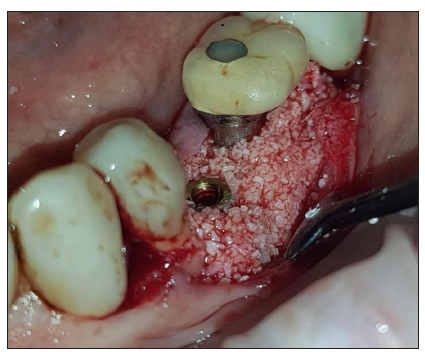
Figure 10:Placement of the Lamina membrane mounted on the customised abutment.

Flaps were closed with 3 layers of sutures (Figure 10)
1) An intermediate layer of monofilament absorbable 4.0
(Glycolon, Resorba, Nuremberg, Germany) adaptation
sutures 1 to 2mm below the muco-gingival line for additional
membrane stabilisation and coronal flap advancement.
2) A superficial layer of vertical mattress and simple interrupted
Glycolon 5.0 sutures for flap closure and papilla stabilisation.
3) A deep layer of Glycolon 5.0 interrupted sutures for apical
repositioning of the mucosa previously dissected with split
thickness preparation in order to avoid any muscle pull.
Post-surgical instructions were given to the patient who was advised to rinse with a disinfectant solution (Blue®M Mouthwash, Blue®M Oral Care) twice a day for 1 month and to avoid brushing at the surgical site during that period until the sutures were completely resorbed. Antibiotics-Augmentin 875mg/125mg 2 times a day for 1 week and Ibuprofen 600mgr - two times a day for 5 days were also prescribed. Recalls were scheduled at 2 weeks, 1, 2, 3 and 4 months.
Case 2- Analogic Workflow
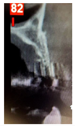
A 54-year-old female patient pretend to our clinic for Implant rehabilitation of an edentulous 23 site where a failed guided bone regeneration took place 4 months before. The patient didn’t have any health issues, was a non-smoker and didn’t have any sign periodontal disease. A diagnostic Cone Beam Computed Tomography showed an important horizontal ridge resorption on site 23, type 3 bone density and enough ridge height (measured from its most coronal edge to the nasal floor) to place a dental implant (Figure 11). Clinical examination revealed a low smile line and the presence of enough thickness of keratinised tissue on the site (Figure 12). Materials used in this case where identical as in case 1. In this case the workflow featured a chairside fabrication of the customised abutment and its adaptation on the membrane during the surgical procedure.
Figure 11:The three layers of sutures:
A. Yellow arrows: Superficial layer.
B. Green arrows: Intermediate layer.
C. White arrows: Deep layer.

Figure 12:Pre-op CBCT Cross sectional image Site 23.
Surgical workflow
Following local anaesthesia (lidocaine Hydrochloride/ Epinephrine tartrate) the workflow consisted of the same surgical procedure steps as in case one. An MIS V3 3.9mm diameter 10mm length Implant and a single unit abutment (Connect 4mm diameter, 2mm height) were placed with a torque of 35N.cm. The site was grafted with sticky bone graft produced by mixing 2gr of Xenograft (Biogen 0.5 gr) and SPRF liquid. Glycolon 4.0 and 5.0 sutures were used for flap adaptation and closure.
Analogue/Chairside customised abutment fabricationand membrane adaptation
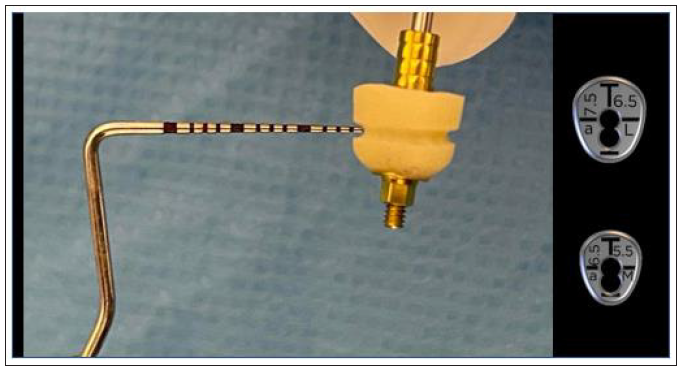
A customised abutment related to an anterior large VPI Cervico guide (aL, Dimensions 7.5x6.5mm) was fabricated on the corresponding mold of the VPI Cervico system using an MIS engaged temporary cylinder for a 4mm diameter Connect single unit abutment and nano-hybrid flowable composite resin material.
A peripheral retain groove of 1mm depth was created using a small round bur 3mm above the abutment’s base (Figure 13). As a section of 1mm on an anterior large abutment (aL, Dimensions 7.5x6.5mm) corresponds to an anterior medium abutment (aM, Dimensions 6.5x5.5mm), an aM cervico guide was used as a reference for shaping the Soft Lamina membrane for further adaptation to the aL profile (Figure 14). The membrane was finally shaped with a 15 blade and scissors according to site topography and attention was given to ensure that the abutment and the membrane were firmly attached to one another at the groove area of the profile unit (Figure 13). Post-surgical instructions were given to the patient as in case 1 and the same medication was prescribed. Recalls were scheduled at 2 weeks, 1, 2, 3 and 4 months.
Figure 13:Pre-op Clinical Situation Site 23.
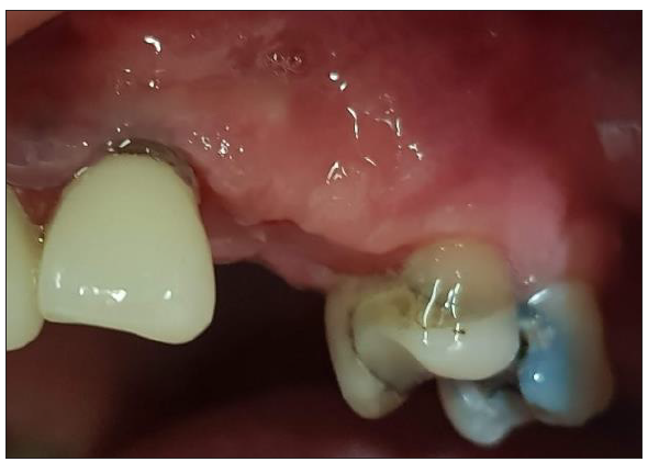
Figure 14:A 1mm depth perimetrical groove 3mm on the aL abutment corresponds to an aM profile.
Results
Clinical re-evaluation of the 2 sites was set at 4 months post op
revealing a cervical profile generation and more precisely:
A. In case 1 keratinised tissue was preserved on both buccal
and lingual sides and supra-crestal complex height [20] of 5mm
(2mm Connect abutment height + 3mm were obtained above the
abutment platform till the marginal soft tissue edge) on the buccal
side and 6mm (2mm Connect abutment height + 4mm measured
above the abutment platform till the marginal soft tissue edge) on
the lingual side were recorded with a periodontal probe (Figure
15).
Figure 15:Shaping the Lamina membrane using the appropriate VPI Cervico guide.
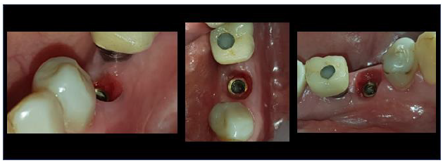
B. In case 2 keratinised tissue was also preserved on both buccal and lingual sides and supra-crestal complex height were identical to those recorded in case 1 (Figure 16).
Figure 16:4-month Post-op Clinical results site 35.
Post-op Computed Tomography revealed in both cases a very
good integration of the implants and more precisely:
A. In case 1 results at 10 months post-op showed enough
bone around the implant 35.
The implant site 36 benefited from the whole procedure as bone formation was evident at the buccal side where a bone defect was recorded in the pre-op CBCT (Figure 17).
Figure 17:4-month Post-op Clinical results site 23.
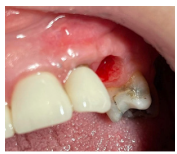
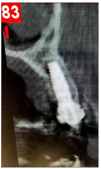
B. In case 2 results at 4 months post op also showed sufficient ridge dimensions with adequate bone around the implant 23 (Figure 18 &19).
Figure 18:10-month Post op CBCT Cross sectional images on sites 35 (left) and 36 (right)
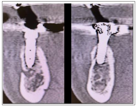
Figure 19:4 month Post op Cross sectional image 23.
Discussion
This article features a novel approach for a single step
optimisation process (O.S.O.) in single implant sites with
simultaneous hard and soft tissue augmentation with the use
of a cortical lamina membrane and customised abutments.
This approach reduces treatment duration and the number of
procedures. This article provides a step-by-step protocol both
adapted to a digital or analogue (chairside) protocol. Nevertheless,
some important points need to be discussed and have to be taken in
account when performing this technique:
A. Envelope flap design should allow access and enough space for
the lamina membrane to be easily positioned over the grafting
material. We recommend that the intra-sulcular incisions
should be extended to the distal aspect of the element that
follows the adjacent to the edentulous site tooth. If there is
no distal element, then the mid-crestal incision should be
extended accordingly.
B. The Flaps should be released enough to completely cover the
lamina membrane placed over the grafting material, otherwise
an early grafting material resorption may occur.
C. We advise to always place the implant sub-crestal to allow
maximum host bone to implant contact with a good primary
stability close to 30N.cm. Bone substitute should be used for
veneer grafting over host bone and cover eventual little buccal
bone post drilling dehiscence. The use of Osseo densification
Densah burs in bone density type 3 and 4 may preserve host
bone during implant site preparation but should be avoided in
high density bone [21].
D. In both cases an intermediate single unit [22] was placed above
the implant prior to the customised abutment’s connexion. The
use of such units, like the connect abutment, prevents grafting
material accumulation over the implant platform that may
create issues for an accurate fitting of posts during impression
stage.
E. We recommend that the retention groove should be located
no more than 3mm above the base of customised abutment.
Regarding its dimensions, a width of 1mm and a depth between
0.5-1mm ensure a firm adaptation of the lamina membrane
around the abutment. Such dimensions also reduce pressure
during the fitting process that might cause membrane rupture.
F. The site should be over grafted to prevent empty spaces
between the lamina membrane and the grafting material.
It also provides further support to the membrane in the
desired level right below the coronally advanced soft tissue.
Biomaterial placed in sticky mode format certainly sets more
easily on the site to be grafted. Furthermore, it enables the
surgeon to place the lamina membrane without displacement
of the grafted granules out of the site.
G. In these two cases three layers of sutures were used for flap
adaptation and closure. The addition of a deep layer of sutures,
with an apical reposition of the mucosa, is optional but we
highly recommend that the operator ensures an absence of
tension over the flap by blocking the muscle pull [23,24].
H. Considering the correct adaptation of the presented protocol
along with the above points in the current clinical practice,
we believe that the simultaneous hard and soft tissue
augmentation and optimisation obtained with this technique
is due to the particular way the lamina membrane is used: its
adaptation and stabilisation around the customised abutment
at the marginal soft tissue level as a shell, protects the over
grafting material. As the membrane further resorbs during
the 4-month healing period, the coronal part of the grafting
material, above the bone level, induces the soft tissue
augmentation and its apical part, on the crestal level and below,
the hard tissue augmentation. The customised abutment
provides a “soft tissue imprint” for cervical profile generation,
stabilises the barrier shell and provides tenting over the bone
graft around the single unit abutment and the implant below.
This article provides proof that the Poncho Lamina technique shows optimal results in hard and soft tissue optimisation in a onestep procedure for single implant sites. It also introduces a novel single step approach that combines bone augmentation, Implant placement, keratinised tissue preservation and cervical profile generation simultaneously. Future integration of the Poncho Lamina technique in current implant treatment practice, may diminish the duration of implant treatment and the number of re-entries to the surgical site, while making the whole process less invasive for the patient. Further prospective and randomised control studies are needed in the future to evaluate the efficiency and the validity of the presented protocol.
Disclosure
The authors report no conflict of interest with anything in this article. No financial support was provided for this clinical investigation.
References
- Serino G, Ström C (2009) Peri-implantitis in partially edentulous patients: association with inadequate plaque control. Clin Oral Impl Res 20(2): 169-174.
- Wenstromm JL, Bengazi F, Lekholm U (1994) The influence of masticatory mucosa on the peri-implant soft tissue condition. Clin Oral Impl Res 5(1): 1-8.
- Souza AB, Tormena M, Matarazzo F, Araújo MG (2016) The influence of the peri-implant keratinised mucosa on brushing discomfort and peri-implant patient tissue health. Clin Oral Impl Res 27(6): 650-655.
- Glauser R, Schűpbach P, Gottlow J, Hämmerle CHF (2005) Peri implant soft tissue barrier at experimental one-piece mini-implants with different surface topography in humans: A light-microscopic overview and histometric analysis. Clin Impl Dent Relat Res 7(Suppl 1): S44-S51.
- Giannobile WV, Jung RE, Schwarz F (2018) Evidence-based Knowledge on the aesthetics and maintenance of peri-implant soft tissues: Osteology Foundation Consencus Report Part 1-Effects of soft tissue augmentation procedures on the maintenance of peri-implant soft tissue health. Clin Oral Impl Res 29(Suppl 15): 7-10.
- Grunder U, Gracis S, Capelli M (2005) Influence of the 3-D bone-to-implant relationship on esthetics. Int J Periodontics Restorative Dent 25(2): 113-119.
- Monje A, Chappuis V, Monje F, Muňoz F, Wang HL, et al. (2019) The critical peri-implant buccal bone wall thickness revisited: An experimental study in the beagle dog. Int J Oral Max Impl 34(6): 1328-1336.
- Beretta M, Poli PP, Pieriboni S, Tansella S, Manfredini M, et al. (2019) Peri-Implant soft tissue conditioning by means of customized healing abutment: A randomized controlled clinical trial. Materials (Basel) 12(18): 3041.
- Sánchez IS, Ortiz Vigón A, Sanz Martín I, Figuero E, Sanz M (2015) Effectiveness of lateral bone augmentation on the alveolar crest dimension: A systematic review and meta-analysis. J of Dent Res 94(9 Suppl): 128S-42S.
- Oh SL, Masri RM, Williams DA, Ji C, Romberg E (2017) Free gingival grafts for implants exhibiting lack of keratinised mucosa: A prospective controlled randomised clinical study. J Clin Periodontol 44(2): 195-203.
- Esposito M, Grusovin MG, Felice P, Karatzopoulos G, Worthingtonet HV, et al. (2009) The efficacy of horizontal and vertical bone augmentation procedures for dental implants-a Cochrane systematic review. Eur J Oral Implantol 2(3): 167-184.
- Mittal Y, Jindal G, Garg S (2016) Bone manipulation procedures in dental implants. Indian J Dent 7(2): 86-94.
- Rossi R, Rancitelli D, Poli PP, Dal Polo MR, Nannmark U, et al. (2016) The use of a collagenated porcine cortical lamina in the reconstruction of alveolar ridge defects. A clinical and histological study. Minerva Stomatol 65(5): 257-268.
- Rossi R, Ghezzi C, Tomecek M (2020) Cortical lamina: A new device for the treatment of moderate and severe tridimensional bone and soft tissue defects. Int J Esthet Dent 15(4): 454-473.
- Vergoullis I, Badell CL, Papadopoulos G (2017) An innovative approach for the selection, generation and recording of a custom emergence profile around implants. Journal of Implants and Advanced Clinical Dentistry 9(5): 6-19.
- Lekholm U, Zarb GA (1985) Patient selection and preparation. In: Branemark PI, Zarb GA, Albrektsson T (Eds.), Tissue integrated prostheses: osseointegration in clinical dentistry, Quintessence Publishing Company, Chicago, USA, pp: 199-209.
- Ronda M, Stacchi C (2011) Management of a coronally advanced lingual flap in regenerative osseous surgery: A case series introducing a novel technique. Int J Periodontics Restorative Dent 31(5): 505-513.
- Koutouzis T, Huwais S, Hasan F, Trahan W, Waldrop T, et al. (2019) Alveolar ridge expansion by osseodensification-mediated plastic deformation and compaction autografting: A multicenter retreospective study. Implant Dent 28(4): 349-355.
- Pelekanos S, Pozidi G (2017) Immediate one-time low -profile abutment to enhance peri-implant soft and hard tissue stability in the esthetic zone. Int J Periodontics Restorative Dent.
- Mattheos N, Vergoullis I, Janda M, Miselli A (2021) The implant supra-crestal complex and its significance for long-term successful clinical outcomes. Int Journal of Prosthodont 34(1): 88-100.
- Huwais S, Meyer EG (2016) A novel osseous densification approach in implant osteotomy preparation to increase biomechanical primary stability, bone mineral density, and bone-to-implant contact. Int J Oral Max Impl 32(1): 1-10.
- Fabbri G, Staas T, Linkevicius T, Valantiejiene V, González Martin O, et al. (2021) Clinical performance of a novel two-piece abutment concept: Results from a prospective study with a 1-year follow-up. J of Clin Med 10(8): 1594.
- Choukroun E, Surmenian J, Simonpieri A, Choukroun J (2021) Oxidative stress and osteoimmunology: The two missing pieces of the oral osseointegration puzzle. Immunology Research and Therapy Journal 3(1): 119.
- Mammoto A, Connor KM, Mammoto T, Yung CW, Huh D, et al. (2009) A mechanosensitive transcriptional mechanism that controls angiogenesis. Nature 457(7233): 1103-1108.
© 2022 Tzovairis Alexander. This is an open access article distributed under the terms of the Creative Commons Attribution License , which permits unrestricted use, distribution, and build upon your work non-commercially.
 a Creative Commons Attribution 4.0 International License. Based on a work at www.crimsonpublishers.com.
Best viewed in


.jpg)


 Editorial Board Registrations
 Submit your Article
 Refer a Friend
 Advertise With Us
.jpg)


.jpg)


.bmp)
.jpg)
.png)
.jpg)


.jpg)


.png)

.png)


.png)


