
- About Us
- Information
-

The Author ensures that the research has been conducted responsibly and ethically with adherence to all relevant regulations. read more..
- For Authors
- For Reviewer
- Manuscript Guidelines
- Membership
- Publication Ethics
-
- Journals
- Reprints
- e-Books
- Videos
- Policies
- Contact Us
 COVID-19
- Submissions


Full Text
Modern Concepts & Developments in Agronomy
Development of a Measuring Apparatus for Aerodynamic Properties of Granular Materials
Audu J*
Department of Agricultural and Environmental Engineering, University of Agriculture, Nigeria
*Corresponding author: Audu J, Department of Agricultural and Environmental Engineering, University of Agriculture, Makurdi, Nigeria
Submission: May 21, 2018;Published: August 17, 2018

ISSN 2637-7659Volume3 Issue2
Abstract
In handling and processing of agricultural products, air or water is often used as a transport medium for separating the desirable product from unwanted materials. When an air stream is used for separating a product from its associated foreign materials, such as straw and chaff, knowledge of aerodynamic characteristics of all the particles involved is necessary. This helps to define the range of air velocities for effective separation of the grain from foreign materials. For this reason, the terminal velocity (Vt) has been used as an important aerodynamic characteristic of materials in such applications as pneumatic conveying and their separation from foreign materials.
Introduction
Khoshtaghazaet al. [1] reported that for conveying agricultural material, the range of proper air streams should be used. With low air speed, there is stagnation in the system, or with high air speed, there is not only energy lost, but also grains may be broken. The proper air speed can be determined from aerodynamic properties of agricultural materials. The relationship between drop in pressure and the rate of airflow through an agricultural product is important in the design of drying or cooling systems [2,3]. Aerodynamic properties include; terminal velocity, drag coefficient, pressure drop and resistance to airflow.
Measurement of these properties on agricultural seeds and grain are difficult especially in developing country where the equipment for doing so may cost several millions of dollars both to purchase and to import into these developing countries. Hence the need to design and construct single equipment for measuring all these aerodynamic properties using locally sourced materials become necessary.
Design Considerations
Motor selection
According to Keyes [4]an electric motor is a device which converts electrical energy into kinetic energy. Single phase induction motors were considered for used in the design becauseKeyes [4]reported that they are used where three phase power is not available; typically in residential, commercial and agricultural applications. They are also used in applications with power requirements below 1 horsepower (HP). UNEP [5] also reported that induction motors are the most common motors used for various equipment’s in industry. Their popularity is due to their simple design, low cost and ease to maintenance.
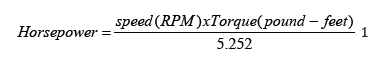
Keyes [4] rated a single-phase motor for 120/240 volts at 60 Hz. Motor speed is commonly stated in Revolutions Per Minute (RPM). Motor horsepower is defined as the rotational speed of the motor multiplied by the torque (eq. 1).
Motor efficiency
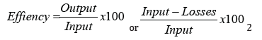
The efficiency of a motor is the ratio of mechanical power output to the electrical power input and is usually expressed as a percentage (Keyes, 2007).Equation 2 illustrate this relationship.
Because the efficiency of a motor is difficult to assess under normal operating conditions, themotor load can be measured as an indicator of the motor’s efficiency (eq.3). As loading increases, the power factor and the motor efficiency increase to an optimum value at around full load[5].
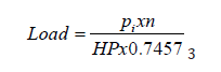
Where
η = Motor operating efficiency in % as provided by the manufacturer
HP = Horse power
Load = Output power as a % of rated power,
Pi= Power in KW
Variable torque loadsare those for which the torque required varies with the speed of operation. Centrifugal pumps and fans are typical examples of variable torque loads (torque varies as the square of the speed).
Life cycle cost of a motor
According to Keyes (2007) an electric motor can consume up to ten times its purchase cost annually over its lifetime which can range from 15 to 25 years or more. Improvements in efficiency can result in substantial savings in life cycle cost which includes the capital and operating costs (eq.4, 5 and 6).
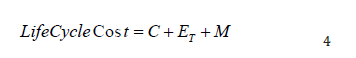
Where
C = Initial capital cost plus installation,
ET = Total energy cost,
M = Total maintenance cost
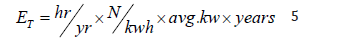
N = Naira (currency),Kwh = kilowatt hour
M = annual(N)xyears
Operating Cost

If the actual motor loading is not known, to calculate for efficiency then an estimate efficiency of 65% can be used.
Fan selection
There are two basic types of air moving devices: the centrifugal fan, and the axial flow fan. Centrifugal fans are those in which air is discharged perpendicular to the impeller axis. Axial fans are those where the airflow through the impeller is mainly parallel to the axis of the rotation. The impeller is confined in a cylindrical housing[6]. Fans, blowers and compressors are differentiated by the method used to move the air, and by the system pressure, they must overcome. According to American Society of Mechanical Engineers (ASME) the specific ratiothe ratio of the discharge pressure over the suction pressure is used for defining the fans, blowers and compressors (Table 1).
Table 1: Differences between fans, blower and compressor

Source: Bureau of Energy Efficiency.
Fan design consideration
Selection of fan should be based on application requirement. According to Greenheck [7]certain criteria must be considered these include;location, orientation, vibration, leakage and sealing, spark resistant construction, special materials, temperature, rate of temperature change. Others are durability and reliability, bearing design, cooling, lube, thermal expansion, erosion, corrosion, Buildup, Special codes and regulations, motors.
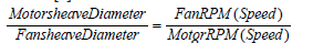
Fan speed (RPM) is determined using equation (8) as reported byARHVAC [8]
Blade passage frequency also called fan tone or noise.Evans [9] is given by (eq. 9)
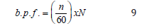
b.p.f. = blade passage frequency (Hz),
n = fan wheel revolution per minute (rpm),
N = Number of impeller blade
Air volume calculation
The Air volume flow rate in a duct can be calculated from the velocity using the equation (10):
Volumetric flow (Q), m3 /sec = Velocity (m/sec) x Area (m2) 10
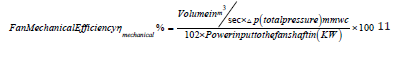
Fan Efficiency
Fan manufacturers generally refer to fan efficiency by two terminologies: mechanical efficiency(sometimes called the total efficiency) and static efficiency. Both terms measure how well the fan converts horsepower into flow and pressure. Equation (11) is use for determining mechanical efficiency.
The static efficiency equation (eq. 12) is the same as the mechanical efficiency except that the outlet velocity pressure is not added to the fan static pressure.

Drive motor KW (power input to the shaft) can be measured by a load analyser. This KW multiplied by motor efficiency gives the shaft power to the fan. Fan efficiencies differ from design to design and by types.
Material and Methods
Motor
A motor was selected with the following properties; single phase, induced start, 240volt, 60Hz, 1100 RPM, 1/15 HP. The diagram of the motor is shown in Figure 1. A light dimmer switch regulated the current going into the motor thereby adjusting the motor speed.
figure 1:Schematic drawing of the selected motor.

FAN
figure 2:Schematic drawing of the constructed fan.

A radial centrifugal fan with a vane was constructed using a 2mm sheet stainless steel. This type of fan was chosen because it produces highpressure, mediumflow, and its efficiency is closeto those of tube-axialfans and its powerincreases continuously. A schematic drawing of the fan and its dimension is shown in Figure 2.
The lower chamber of the apparatus
The lower chamber of the apparatus consists ofanØ480mm hollow circular drum constructed from iron metal sheet 3mm thick, provided with a neck 110mm which house the air straighter. Attached to this drum are two 100mm legs resting on a 200mm iron sheet. Also attached to the drum are the motor and fan. The drum was covered with anØ500mm circular cover with a wire mesh located at the inlet opening to prevent foreign material from following the air into the system. Other dimensions of the lower chamber are shown in Figure 3.
figure 3:Schematic drawing of the constructed lower chamber.

Upper chamber of the apparatus
figure 4:Schematic drawing of the constructed lower chamber.

The upper chamber of the apparatus consists of a 10mm square column 1100mm long with one end coved with metal wire mesh (Figure 4). The column was constructed with an iron sheet and painted to prevent corrosion and rust. Along the length of the column five 10mm holes were drilled at 200mm intervals. Pressure taps measured Ø30mm are welded on the drilled holes to deliver air to the manometer. Another threaded circular iron tubes for closing the open tubes was also constructed. Two houses are attached, one at lowest hollow tube (static pressure tube) and any other iron metal tube along the column (Total pressure tube).
Determination of terminal velocity
The apparatus for determination of terminal velocity is shown in Figure 5. The seed sample whose terminal velocity we want to determine was poured into the air column. The dimmer switch was gradually increased until the required speeds of the fan that suspended the seeds samples were reached. The air velocity that suspend the seed was measured using a digital wind vane anemometer and is taken as the terminal velocity of the sample.
figure 5:Set up for measuring Terminal velocity.

Determination of drag coefficient
Drag coefficient was calculated using equation (13)[10]
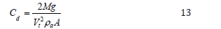
Where
Cd= Drag coefficient,
M = Mass of the particle, kg,
g = Acceleration due to gravity m/s2,
Vt= Air terminal velocity m/s
ρa= Air density kg/m3
Pressure drop and airflow resistance
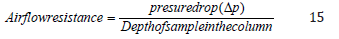
The apparatus shown in Figure 6 was used to measure the pressure drop of the test sample seeds. The test sample seed was poured into the air column to the required depth. The fan was set to the desired airflow rate and the manometer reading was recorded. The pressure drops, and air flow resistance are calculated using equation (14 and 15 respectively) [11,12].
figure 6:Set up for measuring Airflow Resistance.

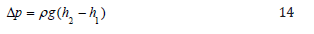
Where
Δp = pressure drop,
ρ = density of air kg/m3,
g = acceleration due to gravity m/s2,
h2 - h1 = height of manometer reading
Conclusion
An apparatus was developed for measuring aerodynamic properties of granular materials. The properties tested were terminal velocity (Vt),drag coefficient (Cd) and pressure drop (Δp) and airflow resistance.Terminal velocities and drag coefficients of agricultural seeds and grains are necessary data used to design and construct a threshing, separating, cleaning and air transporting machines.Pressure drop, and airflow resistance data are necessary for selecting a fan to be used with a drying or cooling system.Before the invention of this measuring apparatus. These aerodynamic properties are measured using different apparatus for each of these properties.This apparatus can only be used for agricultural seeds and grain.All material used to construct this apparatus are locally sourced.
References
- Mohsenin NN (1986) Physical properties of plant and animal material, structure, physical characteristic and mechanical properties. (2nd updated and revised edn) Gordon and breach, science publishers, New York, USA, pp. 841-881.
- Khoshtaghaza MH, Mehdizadeh R (2006) Aerodynamic properties of wheat kernel and straw materials. Agriculture engineering internal: CIGR Journal 8: Fp 05007.
- Rajabipour A, Shabazi F, Mohtasebi S, Tabatabaeefar A (2001) Airflow Resistance in Walnuts. J Agric Sci Tech 3: 257-264.
- Keyes C (2007) Electric Motors, Energy Efficiency Reference Guide. CEA Technologies Inc. (CEATI) Customer Energy Solutions Interest Group (CESIG). Ontario Hydro, Ontario Power Generation Canada, Canada.
- www.energyefficiencyasia.org
- Ivor da cunha, T, Strack SS, (2008) Fans and Blowers. Energy efficiency reference Guide. CEA Technologies Inc. (CEATI) Customer Energy Solutions Interest Group (CESIG). Ontario Hydro, Ontario Power Generation Canada, Canada.
- Greenheck (2006) Greenheck product application Guild. Greenheck Fan Corp Schofield, USA.
- (2006) Application Report Heating ventilation and air conditioning (ARHVAC) Fan Selection for Air Handling Yaskawa Electric America, USA, pp. 1-4.
- Evans BJ (2003) Fan Selection and Size to Reduce Inefficiency and Low Frequency Noise Gemeration. Fan Noise International Symposium Senli, UK, pp 1-7.
- Ayman HAE (2009) Aerodynamic and solid flow properties for flaxseeds for pneumatic separation by using air stream. Int J Agric Bio Eng 2(4): 31-44.
- Sorour HM (2006) A study on pressure drop through bulk of sunflower. Misr J Ag Eng 23(2): 422-433.
- www.saylor.org/site/wp-content/uploads/.../Chapter-3.5-Fans- Blowers.pd.
© 2018 Audu J. This is an open access article distributed under the terms of the Creative Commons Attribution License , which permits unrestricted use, distribution, and build upon your work non-commercially.
Editor In Chief


.jpg)


Signup for Newsletter

Quick Links
 Editorial Board Registrations
 Submit your Article
 Refer a Friend
 Advertise With Us
Our Recent Edition

.jpg)


Top Editors


.jpg)


.bmp)
.jpg)
.png)
.jpg)


.jpg)


.png)

.png)


.png)


Financial Support

Sponsors

Latest e-Books

Latest Video

 a Creative Commons Attribution 4.0 International License. Based on a work at www.crimsonpublishers.com.
Best viewed in
a Creative Commons Attribution 4.0 International License. Based on a work at www.crimsonpublishers.com.
Best viewed in