
- About Us
- Information
-

The Author ensures that the research has been conducted responsibly and ethically with adherence to all relevant regulations. read more..
- For Authors
- For Reviewer
- Manuscript Guidelines
- Membership
- Publication Ethics
-
- Journals
- Reprints
- e-Books
- Videos
- Policies
- Contact Us
 COVID-19
- Submissions


Full Text
Innovation in Tissue Engineering & Regenerative Medicine
Remarks on Parameters Characterizing the Properties of Porous Materials Used in Biomedicine
Juliusz Kulikowski*
Academy of Sciences, Poland
*Corresponding author:Juliusz Kulikowski, Academy of Sciences, Warsaw, Poland
Submission: July 31, 2019;Published: August 07, 2019

Volume1 Issue3August, 2019
Abstract
Critical remarks concerning numerical parameters widely used to characterization of the properties of porous materials are given in the paper. It is shown that discrete form of objects analyzed by computers causes substantial misinterpretations of size and shape of small objects (pore sections), and it leads to inexact evaluation of the porosity parameters and statistics of the examined materials. It is also shown that the non-circularity factor is not a quite reliable parameter characterizing the shape of pores. In Conclusions recommendations for using porosity characteristics, despite their inadequacies, are given.
Keywords: Pores; Porous materials; Porosity characteristics; Discrete geometrical objects
Introduction
Synthetic porous materials play a substantial role in numerous biomedical applications, like tissue engineering, blood rectification, dressing materials design etc. Controlling the structural parameters of pores: their size, form and interconnectivity as well as monitoring the stability of the parameters are important components of the processes of porous material production. On the other hand, some authors pay attention to the influence of structural pores’ parameters on final properties of porous materials, like permeability for fluids and small particles or providing a microenvironment for cells adhesion to the pore walls, their proliferation and differentiation [1-5]. The computer-aided analysis of microscope images of porous materials cross-sections occur to be an effective tool for the assessment of the materials’ characteristics [6]. Among the geometrical and morphological properties, the pore size, non-circularity and their statistical distributions are the most frequently ones taken into consideration [7]. However, it should be remarked that the above-mentioned characteristics usually concern the 2D sections of pores but not the pores as 3D objects themselves. Moreover, the numerical values of geometrical parameters of small objects (like pores) substantially depend on the assumed type of geometry (Euclidean or discrete) and in the case of discrete geometry they also depend on the assumed type of connectivity (4- or 8-connectivity of points on a rectangular grid, typical for computer data processing [8]). Below, some critical remarks concerning numerical characteristics of pores are more exactly presented.
Numerical Characteristics of Pores
Discrete objects interpretation
Figure 1:Typical microscope image of a porous material cross-section.

In Figure1 a typical scanning electron microscope (SEM) image of porous material cross-section, subjected to several preliminary operations making easier its computer analysis, is shown. A large variety of pores’ size and irregularity of their form is here remarkable. The problem consists in computer-aided evaluation of selected parameters characterizing the porosity of the given sample of porous material.
One of basic parameters characterizing a porous material is the porosity factor [9]:
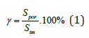
where Spor denotes a total area of visible pore cross-sections, Sim stands for the total image area.
Another important characteristic of a porous material is its porosity histogram χ (S) , defined as a function describing normalized frequency of occurring pores dependently on their size.
Basic measurable geometrical parameters in computer-aided image analysis are length l of lines and surface S of selected 2D objects. For this purpose, some basic concepts of discrete geometry should be used.
Discrete objects are defined as subsets of pixels selected due to their brightness intensity criterion. Points, by definition, are discrete objects represented by pixels not (4- or 8-) connected to any other pixel; lines – by ordered sequences of pixels connected to at most two other pixels of the object. Each 2D object is assumed to be contoured. Contours are defined as lines consisting of pixels belonging to the object and (4- or 8-) connected to at least one pixel not belonging to the given object. Object’s interior consists of object pixels not belonging to its contour.
In any case, a numerical assessment of any geometrical
parameter needs a preliminary selection of pixels belonging to
the object being of interest. The length l expressed in screen units
[su] (which can easily be recalculated into metric units) is defined
as the number η1
of interconnections between the pairs of pixels
constituting the line. The surface S, expressed in square screen
units [squ], is defined as the sum int
 where ηint is the number
of pixels constituting the object interior while ηc
is the number of
pixels constituting the contour.
where ηint is the number
of pixels constituting the object interior while ηc
is the number of
pixels constituting the contour.
The above given set of assumes is a basis of numerous computer
programs of image analysis. However, in some cases they may lead
to misunderstandings, as it will be shown below. Figure 2 shows
a given configuration of pixels which in different ways should be
contoured under the assumption of 4- and 8-connectivity. In the
4-connectivity sense (case a)) the contour consists of 4 disjoin parts
whose total length equals 8 [su]. In the 8- connectivity sense (case
b)) the contour has the form of a closed line whose length equals
16 [su]. The estimated size (area) in both cases (but only in this
example!) is equal:  [squ] in the case a) and
  [squ] in the case b).
Figure 2:The same discrete object contoured in the sense of:
a) 4-connectivity (contour discontinuous),
b) 8-connectivity

Figure 3:Different interpretations of contours:
a) pixels in circles don’t belong to the contour in the 4-connectivity, belong to it in the 8-connectivity sense,
b) two objects in 4-connectivity, one object in 8-connectivity sense.

Figure 3 illustrates the case of different interpretation of
objects in 4- and 8-connectivity sense. The object shown in (Figure
3a) in the 4-connectivity sense (case I)) contains 4 interior points,
while in 8-connectivity sense (case II) it does not contain any
interior points. The estimated parameters will then be: case I: l =
6 [su],  [squ]; case II: l = 12,
  [squ]. (Figure 3b)
presents: two separate objects in the 4-connectivity or one object in
the 8-connectivity sense. Such duality of interpretation may cause
substantial differences in results of counting pores and statistical
parameters evaluation. Moreover, the effects of size-based
classification of pores are strongly dependent on the magnification
of the images of porous materials cross-sections.
[squ]. (Figure 3b)
presents: two separate objects in the 4-connectivity or one object in
the 8-connectivity sense. Such duality of interpretation may cause
substantial differences in results of counting pores and statistical
parameters evaluation. Moreover, the effects of size-based
classification of pores are strongly dependent on the magnification
of the images of porous materials cross-sections.
Shape characterization
Shape is another important pore feature whose evaluation depends on the effects of discrete objects contouring. We are able to visually distinguish the oval, elongated, branched and more complicated shapes of pore cross-sections. For pore characterization numerical shape characteristics are preferred. Among them the smallest rectangle circumscribing the pore crosssection seems to be the simplest and the most convenient one. If dmax and dmin are the lengths of, respectively, the maximal and the minimal side of rectangle, then the ratio:
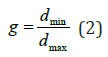
can be established as a compactness coefficient of the rectangle, equal 1 for a square and decreasing to 0 as the rectangle is in one direction up to infinity elongated. The same coefficient can be used to any irregular 2D figure closely circumscribed by the rectangle. However, for this purpose generation of rectangles of any size, position and orientation angle on a plane is necessary. Alas, the notion of a rectangle fully equivalent to this used in Euclidean geometry, in discrete geometry does not exist. Consequently, the above-presented compactness coefficient cannot be used but to characterization the shape of large pores. An alternative possibility to shape of pores parameterization is based on the contour folding concept. It takes the form of a contour folding coefficient expressed by the formula:
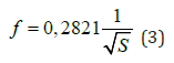
where, once again, l stands for the contour length and S-for object surface. The coefficient f takes value 1 for circles and increases infinitely when contours take more irregular form.
The main critical remark about this concept is caused by the
fact that the contour folding coefficients of some different shape
objects may be equal, as illustrated by (Figure 4a & 4b). The two
objects have the same contour lengths l = 24 [su], surfaces S =
 [squ] and contour folding coefficients f = 1,382. Remark
also that both figures can be inscribed into 7×7 -size squares.
Therefore, using this approach, as an auxiliary one to improve
shapes discrimination, in this case would be ineffective. Finally, it
should be also remarked that magnification of images destined to
computer analysis as well as some widely used preliminary image
enhancement operations (e.g. noise filtering, morphological closure
and/or opening, thresholding, etc. [10]) substantially influence on
pore size and visibility.
[squ] and contour folding coefficients f = 1,382. Remark
also that both figures can be inscribed into 7×7 -size squares.
Therefore, using this approach, as an auxiliary one to improve
shapes discrimination, in this case would be ineffective. Finally, it
should be also remarked that magnification of images destined to
computer analysis as well as some widely used preliminary image
enhancement operations (e.g. noise filtering, morphological closure
and/or opening, thresholding, etc. [10]) substantially influence on
pore size and visibility.
Figure 4:Two objects of the same size and non-circularity coefficient but different shapes.

Conclusion
Computer-aided image processing methods are an effective tool for evaluation of porous materials properties. However, their effectiveness depends on adequate choosing parameters characterizing pores. In most cases they are based on geometrical parameters, like length of contours or surface of planar crosssections of pores. Numerical values of such parameters in discrete geometry used by computers are not identical to those measured in Euclidean geometry. Moreover, they also depend substantially of the assumed connectivity of points in discrete geometry. This leads to misinterpretations and errors in parametric characterization of pores. For this reason, if any numerical parameters of material porosity resulted from computer-aided analysis are presented, the formal assumptions the corresponding computer program has been based on should be clearly explained. Otherwise, the results can be incomparable. On the other hand, the differences between various methods of porosity parameterization may be inessential if a method (despite of its deficiencies) to control and compare the results reached within a given series of experiments is used.
References
- O’Brien FJ, Harley BA, Yannas IV, Gibson LJ (2005) The effect of pore size on cell adhesion in collagen-GAG scaffolds. Biomaterials 26(4): 433-441.
- Murphy CM, Haugh MG, O’Brien FJ (2010) The effect of mean pore size on cell attachment, proliferation and migration in collagen-glycosaminoglycan scaffolds for bone tissue engineering. Biomaterials 31(3): 461-466.
- Silva MMCG, Cyster LA, Barry JJA, Yang XB, Oreffo ROC, et al. (2006) The effect of anisotropic architecture on cell and tissue infiltration into tissue engineering scaffolds. Biomaterials 27(35): 5909-5917.
- Stenhamre H, Nannmark U, Lindahl A, Gatenholm P, Brittberg M (2011) Influence of pore size on the redifferentiation potential of human articular chondrocytes in poly (urethane urea) scaffolds. J Tissue Eng Regener Med 5(7): 578-588.
- Nuernberger S, Cyran N, Albrecht C, Redl H, Vécsei V, et al. (2011) The influence of scaffold architecture on chondrocyte distribution and behavior in matrixassociated chondrocyte transplantation grafts. Biomaterials 32(4):1032-1040.
- Chwojnowski A, Przytulska M, Wierzbicka D, Kulikowski J, Wojciechowski C (2012) Membranes’ porosity evaluation by computer-aided analysis of SEM images- a preliminary study. Biocybernetics and Biomed Eng 32(4): 67-75.
- Wu Q, Wu B (1995) Study of membrane morphology by image analysis of electron micrographs☆. Journal of Membrane Science 105(1-2): 113-120.
- Russ JC (2011) The image processing handbook. (6th edn), CRC Press, Boca Raton, Florida, USA.
- Przytulska M, Kulikowski J (2017) Multi-aspect assessment and classification of porous materials. In: Kurzynski M, et al. (Eds.), Advances in Intelligent Systems and Computing (578), Springer International Publishing AG, Basel, Switzerland, pp. 22-32.
- Przytulska M, Kulikowski JL, Wierzbicka D (2015) Biomedical images enhancement based on the properties of morphological spectra. Biocybernetics and Biomed Eng 35(3): 206-215.
© 2019 Juliusz Kulikowski. This is an open access article distributed under the terms of the Creative Commons Attribution License , which permits unrestricted use, distribution, and build upon your work non-commercially.
Editor In Chief


.jpg)


Signup for Newsletter

Quick Links
 Editorial Board Registrations
 Submit your Article
 Refer a Friend
 Advertise With Us
Our Recent Edition

.jpg)


Top Editors


.jpg)


.bmp)
.jpg)
.png)
.jpg)


.jpg)


.png)

.png)


.png)


Financial Support

Sponsors

Latest e-Books

Latest Video

 a Creative Commons Attribution 4.0 International License. Based on a work at www.crimsonpublishers.com.
Best viewed in
a Creative Commons Attribution 4.0 International License. Based on a work at www.crimsonpublishers.com.
Best viewed in