
- About Us
- Information
-

The Author ensures that the research has been conducted responsibly and ethically with adherence to all relevant regulations. read more..
- For Authors
- For Reviewer
- Manuscript Guidelines
- Membership
- Publication Ethics
-
- Journals
- Reprints
- e-Books
- Videos
- Policies
- Contact Us
 COVID-19
- Submissions


Full Text
Examines in Physical Medicine and Rehabilitation: Open Access
Finger Angle and Force Estimation Using Musculoskeletal Model on Thumb and Index Finger
Sorawit Stapornchaisit1, Yeongdae Kim1, Natsue Yoshimura2 and Yasuharu Koike2*
1Department of Information and Communication Engineer, Tokyo Institute of Technology, Tokyo, Japan
2Institute of Innovative Research, Tokyo Institute of Technology, Yokohama, Japan
*Corresponding author: Yasuharu Koike, Institute of Innovative Research, Tokyo Institute of Technology, Yokohama, Japan
Submission: August 11, 2020; Published: September 08, 2020

ISSN 2637-7934 Volume3 Issue1
Abstract
Prosthetic hand control system usually controls finger using pattern recognition from surface Electromyography (EMG) signal from the forearm, as most of the finger muscles are located in the forearm with small tendon connected to the finger skeletal. However, pattern recognition can provide only limited posture and grip motion which is different from natural musculoskeletal models of hand. Although, every finger provide contribution to daily activity, but more than half of all hand functions are made possible by the thumb and index finger. Therefore, this research will be limited to thumb and index finger to simplify the signal processing and analysis method. The proposed method used sEMG from muscles and simple movement of flexion and extension to estimate equilibrium position and stiffness with one Degree of Freedom (DOF) for each finger call musculoskeletal model. Our research interested in using the same principle of the musculoskeletal model to estimate equilibrium position and stiffness of thumb and index finger separately by measuring position in 3-dimensional space. The result will be confirmed by measuring position, force and EMG of the subject simultaneously.
Keywords: Finger angle; Finger stiffness; Musculoskeletal models; Prosthetic hand control system; Surface electromyography (sEMG)
Introduction
A large number of researchers have been studying on building prosthetic hand and finger to replicate actual hand and finger movement using Surface Electromyography (sEMG) signal as control signal to provide some degree of freedom for amputee [1-6]. The motions of thumb and index finger which provide more than half of hand functions are controlled by multiple muscles located in forearm and connect to finger skeleton by tendon [7]. Although science understands the relation between muscle activity and finger motion, but most prosthetic arms still operate using the conventional method of pattern recognition such as machine learning and artificial neuron network.
One of the most accepted prosthetic hand created recently is PRODIGITS by Touch Bionics in Scotland [8] and its later version of iLimb Ultra revolution with lighter and more anatomically accurate fingers with Bluetooth connectivity [9]. Conventional method provides reliable control methodology with a relatively simple structure that can compensate for differences in anatomy for each individual. However, there are still needs for pre-defined posture (grip patterns) and support from engineer/physiologist to help the operator add, adjust or modify the posture/motion. Moreover, the conventional method limits the motion of prosthetic hand finger depending on the instability of sEMG signal [1-4].
In order to overcome such limitation, this paper proposed a new control method using Musculoskeletal Model (MSM). The experiment will separate into two parts, isometric (muscular contraction against resistance in which the length of the muscle remains the same) and isotonic (muscular contraction against resistance in which the length of the muscle changes). In isometric experiment, the force and sEMG signals were measured using Reach Man Robot [10,11]. While in isotonic experiment, finger angle was measured using motion capture (Optitrack system) and sEMG signal simultaneously. Finally, the statistical performance indicator of each set of data were correlation coefficient and root mean square error.
Methodology
The method used to calculate thumb and index finger angle from surface EMG signal is mathematic equation derived from MSM. Stiffness and force command were converted into torque using simple spring theory, then applied to motor (Figure 1).
Figure 1: Two muscles (flexor and extensor) connect to the joint via tendon and force of each muscle were controlled by muscle activations and joint angles.

Musculoskeletal model
The musculoskeletal model (MSM) is the developed version of Mykin model [12]. Two muscles (flexor and extensor) connect to the joint via tendon and force of each muscle were controlled by muscle activations and joint angles as shown in Figure 2. The muscles work as an independent group and provide almost uniform motions for flexion and extension of the finger [12]. In this paper, the flexion muscle is referred as Muscle 1 and extension muscle is referred as Muscle 2. According to Wondae R et al., the location of sEMG sensor should be identified via the anatomy and general muscles location in the human forearm [13]. Therefore, the research started from selecting interested muscles pair, that is contract in opposite motion of flexion and extension and are relatively large to acquired best signal to noise ratio. In this paper, the muscles that provide flexion-extension motion and locate in forearm area were selected as:
For thumb finger
A. Flexor pollicis longus muscle (FPL)
B. Extensor pollicis brevis muscle (EPB)
For index finger
A. Flexor digitorum superficialis (FDS)
B. Extensor digitorum (ED)
The location of muscles was confirmed by measuring sEMG signal while asking the subject to move the finger in flexion and extension motions.
Muscles tension
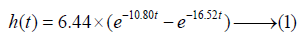
The muscle tension or force was calculated from muscles activity in which referred by sEMG signal of muscles i when i represent flexion muscle and extension muscle as 1 and 2, respectively. The sEMG signal was rectified, noise level rejected and normalized with filters of the following low-pass filters with impulse response characteristics shown in equation (1). The characteristics were derived from the study on estimation of joint torque with neural networks which reproduce latent, contraction and relaxation perEPMR between sEMG signal and muscle tension [14].
The tension Fi of muscles i is expressed as (2)

The parameter ai denoted moment arm of muscle i; k0i, k1i, l0i, l1i, parameters (all in positive values) to define the characteristics of muscle i. θ indicated the joint angles, where angle in flexion was expressed as positive. Signs for moment arm were expressed as follow to indicate the effects resulting from the difference in position of the muscles: a1 > 0, a2 < 0.
Joint torque, equilibrium points and stiffness
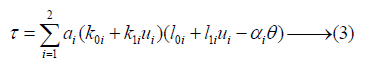
The torque of each muscle represented by muscle contraction, string constant, and length of muscles, which were separated between flexor and extensor. The torque of said joint was expressed by adding up torque of flexor and extensor as shown in equation (3) [6], where torque in the flexion direction was expressed as the positive value.
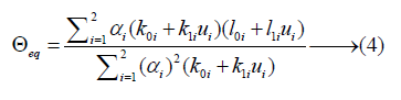
Equilibrium point of the joint was calculated by solving (3) for the joint angle that τ = 0. Equilibrium points were defined as the angles at which torque generated by muscles was balanced to stop when no external forces were applied to the joints as shown in Figure 3 & 4.
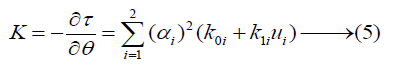
Stiffness K was defined by torque generated by displacement between equilibrium point and joint angles or partially differentiating (3) by joint angles (θ) as shown in (5).
Therefore, the simple spring equation could represent the relations between joint torque, equilibrium point, and stiffness K as show in (6).
Experiment protocol
In this study, we used MSM and LRM to estimate finger angle and force from EMG signal. However, due to technical limitation we could not measure both finger angle and force at the same time, resulting in separation of the experiment into two parts of finger angle experiment and finger force experiment.
Finger angle experiment
In order to confirm the performance of MSM on finger, we designed the experiment protocol to measure finger muscle activity and finger motion, simultaneously. The motion we were interested in this research was thumb flexion, thumb extension, index flexion, and index extension. Previous research provided experiment protocol which able to avoid muscle fatigue [6]. The protocol was 3 seconds of activation and 3 seconds of rest between activations. In one trial, in order to ensure the performance of our model to estimate small force, we separated flexion motion into full flexion and half flexion as shown in Figure 2.
Figure 2: The protocol was 3 seconds of activation and 3 seconds of rest between activations. In one trial, in order to ensure the performance of our model to estimate small force, we separated flexion motion into full flexion and half flexion.

Finger force experiment
In order to measure the force from finger, we used replicate version of ReachMan robot [10] and designed to separate each side of ReachMan robot to accommodate only thumb and index finger as shown in Figure 3. The experiment protocol was similar to previous finger angle experiment but reduce number of trails to 3 trials per finger to reduce fatigue.
Figure 3: In order to measure the force from finger, we used replicate version of ReachMan robot [10] and designed to separate each side of Reach Man robot to accommodate only thumb and index finger.

Performance indicator
As the number of subjects and trials included in this study were large. We would like to represent the performance using performance indicators for each subject. We selected 2 indicators of Correlation Coefficient (CC) and Root-Mean-Square-Error (RMSE).
Experiment setup
The experiment performed on 10 right-handed male subjects age between 21-28 years old with an average age at 25.2. Subjects were given a command by stimulus program showing the preferred action on the screen which was 2.5 meters away as shown in Figure 4. The motion of fingers was captured by Optitrack with Baseline Upper Body + Fingers (33). The markers were placed on proximal interphalangeal joints of thumb finger, distal interphalangeal joints of the index finger, and proximal interphalangeal joints of index finger according to human anatomy.
Figure 4: Subjects were given a command by stimulus program showing the preferred action on the screen which was 2.5 meters away.

Surface EMG sensors with local reference were placed on Flexor Pollicis Longus (FPL), Flexor Digitorum Superficialis (FDS), Extensor Pollicis Brevis (EPB), and Extensor Indicis (EI) as shown in Figure 5. The wireless EMG sensor and optical motion capture were used to ensure maximum freedom of motion while measuring finger angle and EMG signal, simultaneously. The data from both devices were synchronized and stored using LSL (Lab Streaming Layer). Each subject performed at least 10 trials with 5 trials for variable estimation and 5 trials for verification choosing randomly. In each trial, the calibration perEPMR was set at the start of the trial to reduce noise.
Figure 5: Surface EMG sensors with local reference were placed on Flexor Pollicis Longus (FPL), Flexor Digitorum Superficialis (FDS), Extensor Pollicis Brevis (EPB), and Extensor Indicis (EI).

Result
Finger angle experiment
The result show 5-10% better performance for MSM method in CC value and RMSE (RMSE is 0.05-0.10 pi) as shown in Figure 6. The p-value of CC values and RMSE between MSM and LRM calculated by using pair t-test < 0.05 which were considered statistically significant.
Figure 6: The CC and RMSE between estimated finger angle and measure finger angle. Estimated model have 2 model, musculoskeletal model (MSM) and linear regression model (LRM).

Finger force experiment
The result show 2-3 % better performance for MSM method in CC value and RMSE (RMSE is 0.02-0.03 pi) as shown in Figure 7. The p-value of CC values and RMSE between MSM and LRM calculated by using pair t-test > 0.05 which were considered no statistically significant difference between MSM and LRM for force estimation.
Figure 7: The CC and RMSE between estimated finger torque and measure finger torque. Estimated model have 2 model, musculoskeletal model (MSM) and linear regression model (LRM).

Discussion
Generally, the statistical analysis showed high correlation between sEMG signal and thumb, index angle estimated by MSM and LRM. MSM showed better performance due to 2-order regression. However, MSM was still unable to maintain finger angle during smaller activation after motion due to its lack of damper element. For the first experiment, the result highly showed consistence CC with different around 0.04±0.06 for thumb finger and 0.08±0.06 for index finger which was relatively low in term of CC value (Figure 4 & 5). This indicated that MSM and LRM performed very similarly with small improvement. In term of RMSE, it showed similar improvement in the same trend as CC value. Some subject such as subject 8 and 10 showed very small improvement in both CC and RMSE. This indicated the relation between sEMG and finger angle of those subjects to be almost first-order linear. The average RMSE of finger angle was 20 degree which was around 10% (range is 180 degree), This error came from sEMG signal reduction after the target position was reached.
For the second experiment, the result was still consistence for thumb finger but less consistence in index finger. In some subject, the force estimated using LRM showed better performance. The different between MSM and LRM also became much smaller, indicated that finger force might be able to represent using only 1-order linear regression. MSM also showed deep dip before force activation. This happened because subject unconsciously extended their fingers before the experiment which could be reduced by repeating the experiment multiple times on one subject. However due to muscles fatigue, we try to limit the number of repeated experiments to as small as possible for each subject.
The results of MSM and LRM in force were not different because the relation between EMG signal and force from finger was linear. Therefore, MSM did not provide any advantage over LRM.
Acknowledgment
We thank all subjects who participated in the experiments. This work is supported by the MEXT scholarship and by the JSPS KAKENHI (grant no. 19H05728); Tateishi Science and Technology Foundation (grant no. 2188001); JST PRESTO (Precursory Research for Embryonic Science and Technology) (grant no. JPMJPR17JA); and JST MIRAI (grant no. JPMJM18C8).
References
- Bai D, Xia C, Yang J, Shouxian Z, Yinlai J, et al. (2016) Shoulder joint control method for smart prosthetic arm based on surface EMG recognition. In 2016 IEEE International Conference on Information and Automation (ICIA), pp. 1267-1272.
- Clancy EA, Bida O, Rancourt D (2006) Influence of advanced Electromyogram (EMG) amplitude processors on EMG-to-torque estimation during constant-posture, force-varying contractions. Journal of Biomechanics 39(14): 2690-2698.
- Haris M, Chakraborty P, Rao BV (2015) EMG signal-based finger movement recognition for prosthetic hand control. In 2015 Communication, Control and Intelligent Systems (CCIS), pp. 194-198.
- Kawano T, Koganezawa K (2016) A method of discriminating fingers and wrist action from surface EMG signals for controlling robotic or prosthetic forearm hand. In 2016 IEEE International Conference on Advanced Intelligent Mechatronics (AIM), pp. 13-18.
- Khushaba RN, Kodagoda S (2012) Electromyogram (EMG) feature reduction using mutual components analysis for multifunction prosthetic fingers control. In 2012 12th International Conference on Control Automation Robotics & Vision (ICARCV), pp. 1534-1539.
- Sahoo S, Korrapati M, Hota RK, Kumar CS (2016) Bond graph modelling of a tendon driven prosthetic hand finger for motion and impedance control. In 2016 International Conference on Robotics and Automation for Humanitarian Applications (RAHA), pp. 1-6.
- (2015) Burn of Wrist and Hand. MD Guidelines, Japan.
- Eisenberg A (2010) Grabbing gracefully, with replacement fingers. New York Times.
- Melanson D (2013) Touch Bionics latest ‘i-limb’ offers a powered rotating thumb, smartphone controls. 4(20): 15.
- Zhu TL, Klein J, Dual SA (2014) Reach MAN2: A compact rehabilitation robot to train reaching and manipulation. In 2014 IEEE/RSJ International Conference on Intelligent Robots and Systems, pp. 2107-2113.
- Shin D, Kim J, Koike Y (2009) A myokinetic arm model for estimating joint torque and stiffness from EMG signals during maintained posture. Journal of Neurophysiology 101(1): 387-401.
- Ryu W, Han B, Kim J (2008) Continuous position control of 1 DOF manipulator using EMG signals. In 2008 Third International Conference on Convergence and Hybrid Information Technology 1: 870-874.
- Lacquaniti F, Maioli C (1989) The role of preparation in tuning anticipatory and reflex responses during catching. Journal of Neuroscience 9(1): 134-148.
- Koike Y, Kawato M (1995) Estimation of dynamic joint torques and trajectory formation from surface electromyography signals using a neural network model. Biological Cybernetics 73(4): 291-300.
© 2020 Yasuharu Koike. This is an open access article distributed under the terms of the Creative Commons Attribution License , which permits unrestricted use, distribution, and build upon your work non-commercially.
Editor In Chief


.jpg)


Signup for Newsletter

Quick Links
 Editorial Board Registrations
 Submit your Article
 Refer a Friend
 Advertise With Us
Our Recent Edition

.jpg)


Top Editors


.jpg)


.bmp)
.jpg)
.png)
.jpg)


.jpg)


.png)

.png)


.png)


Financial Support

Sponsors

Latest e-Books

Latest Video

 a Creative Commons Attribution 4.0 International License. Based on a work at www.crimsonpublishers.com.
Best viewed in
a Creative Commons Attribution 4.0 International License. Based on a work at www.crimsonpublishers.com.
Best viewed in