
- About Us
- Information
-

The Author ensures that the research has been conducted responsibly and ethically with adherence to all relevant regulations. read more..
- For Authors
- For Reviewer
- Manuscript Guidelines
- Membership
- Publication Ethics
-
- Journals
- Reprints
- e-Books
- Videos
- Policies
- Contact Us
 COVID-19
- Submissions


Full Text
Evolutions in Mechanical Engineering
Elastic Stress-Strain State of the Cast Internal Casing of the K-330-23.5 Turbine for Supercritical Steam Parameters
Serhii Palkov1*, Ihor Palkov2 and Iryna Reshytko3
1Assistant of the Department of Structures and Projecting of Rocket Technology, National Aerospace University “Kharkiv Aviation Institute”, Ukraine
2Deputy Chief Designer of Steam Turbines, Design Department, JSC Ukrainian Energy Machines, Ukraine
3Leading Engineer, Design Department, JSC Ukrainian Energy Machines, Ukraine
*Corresponding author:Serhii Palkov, Assistant of the Department of Structures and Projecting of Rocket Technology, National Aerospace University “Kharkiv Aviation Institute”, Ukraine
Submission: December 09, 2023;Published: January 24, 2024

ISSN 2640-9690 Volume5 Issue2
Abstract
The paper considers the methods of the design analysis of the elastic stress-strain state of cast internal high-pressure casing of 330MW steam turbine is estimated using a three-dimensional computational structural model. The study of this problem is performed using the calculated methods of the volumetric stress-strain state based on the provisions of the theories of elasticity. The problem of determining the stress-strain state of the internal high-pressure casing of the K-330-23.5 turbine in a three-dimensional setting is solved by using the finite element method. The created finite element models consider the contact interaction of the flanges of the two casing halves in the horizontal connector zone. In contact zones, the mesh thickens. Results of the calculated estimation of the stress-strain state of the internal high-pressure casing of steam turbine are given for the elastic deformation, considering the influence loads arising during the installation and operation of the turbine. During the stress-strain state studies, the main zones of stress concentration in internal casing of a K-330-23.5 steam turbine were established.
Keywords:Turbine; Flange connection; Finite element
Abbreviation:SSS: Stress-Strain State; HP: High Pressure; FEM: Finite Element Method; FE: Finite Element; PU: Power Units; SACSP: Super and above Critical Steam Parameters; CFB: Circulating Fluidized Bed Boilers; CCGT: Combined Cycle Gas Turbines; TPP: Thermal Power Plant; JSC: Joint-Stock Company; PM: Penalty Method; LMM: Lagrange Multiplier Method
Introduction
300 to 800MW turbines were created in the 60s and 70s of the twentieth century to carry the base loads of power systems. Their further use to provide maneuverable, semi peak and peak loads has created a number of challenges related to the reliability, maneuverability and economical operation of equipment. And if until the 80s scientific research was aimed at studying thermo gas dynamic processes occurring in flow paths, starting from the 70s, much attention was paid to ensuring the reliability of turbines, investigating their thermal, thermal stress and thermal strain states [1-4]. 300 and 500MW solid fuel power generating units are supposed to be replaced with upgraded PUs of increased efficiency with a steam temperature of 565/565 ͦC or PUs with SACSP, while 300MW power units allow for installing CFB; 150 to 200MW solid fuel PUs should be upgraded by implementing operation with CFB, and later by using CCGT with a fluidized bed under pressure and with coal gasification. According to the requests by domestic and foreign power engineers (Slovyanska TPP, Novocherkasska TPP, Troitska TPP, Ekibastuzska TPP, Aksu TPP), to replace obsolete and worn-out turbines with a capacity of 300, 500, and 800MW, specialists from JSC Turboatom have developed new up to date cost effective and reliable turbines designed to operate with improved parameters of live steam. To revamp Unit No. 6 at Slovyanska TPP by erecting two power units, Unit No. 6b and Unit No. 6a, JSC Turboatom has completed a project of a turbine operating at supercritical steam parameters with an installed electrical power of at least 330MW each, in the bay of dismantled equipment a two-shaft PU No. 6 with an electrical capacity of 800MW in the existing main building of Slovyanska TPP.
The purpose of the above revamping was to:
A. Increase the reliability of the TPP operation by replacing
the obsolete and worn-out PU, which has worked out its life limit,
with two new advanced PUs with an in-stalled electrical capacity of
at least 330MW.
B. Erect new power units on the vacant site by carrying out
dismantling work on the site of the decommissioned inefficient and
environmentally unsafe PU No. 6.
C. Extend the service life of Slovyanska TPP through the
construction of highly efficient PUs for supercritical parameters
with an extended range of PU load regulation.
Further development of turbine engineering, associated with an increase in the initial parameters of steam, an increase in the unit capacity of turbine units, the drive for reducing their dimensions and masses, largely depend on an increase in the reliability and durability of turbine parts and assembly units, which include cast cylinder bodies. To assess the strength of the cast HP casing, which is one of the most critical and expensive elements of a steam turbine, limiting its service life, it is required to investigate its stress-strain state with respect to the operating conditions, caused by inhomogeneous temperature fields and internal pressure of the steam flow. In this regard, the correct assessment of the thermal stress state of the turbine casings is becoming ever more important. Since in most turbine casing elements the forces between parts are transferred by means of contact, and their temperature and strength are determined by the nature of the distribution of contact pressure, it becomes relevant to build refined models and methods for calculating the SSS of a structure in the contact setting [2]. A consistent consideration of these factors in determining and analyzing the SSS of the internal HP casing of the K-330-23.5 steam turbine will make it possible to determine the degree of their influence on the real SSS picture, which will further allow us to evaluate the compliance of the results at each stage of solving the problems set by comparing them with the data of experiments and operation [2].
Problem Statement and Description of Calculation Methods
Formulation of the problem
At this stage, the SSS problem of the internal HP casing of the K-330-23.5 steam turbine operating at supercritical steam parameters (560 ͦС and 23.5MPa) is solved in an elastic setting, without taking into account the influence of temperature stresses and deformations as well as with taking into account (Figure 1).
Figure 1:Three-dimensional model of the K-330-23.5 steam turbine internal HP casing. Loading scheme. Boundary conditions for fastening the casing.

a) Different longitudinal pressure on the walls of the casing.
Determined from the loading scheme as the difference between
the pressure on the external casing wall-loads of group “I”, and
pressures on the internal casing wall-loads of group “II”.
b) The distributed load on the bores for installing diaphragms
in the casing. In the loading diagram-loads of group “III”.
c) The degree of tightening flanged joint fasteners made of
EP-182 (20Kh1M1F1TR) steel and modeled in accordance with [5].
In the loading diagram-loads of group “IV”.
d) Contact interaction in the flanged joint in the joint area.
e) Influence of weight loads.
The boundary conditions simulating the fastening of the casing in models [2]. The rigid fastening in the area where the lower casing half rests on claws and the restricting movement along the joint face in the area where the casing claws rest against the external casing grooves (Figure 1).
Description of the computational model
The three-dimensional model of the internal HP casing of the K-330-23.5 steam turbine was developed in the Autodesk Inventor Professional software package [2,6] and is now presented in Figure 1. The upper and lower halves of the casings relate to 24 studs. The above-mentioned three-dimensional models also include symmetrical contact interaction of the flanges of the two halves of the internal HP casing, which allows us to more accurately determine its SSS. The FE model under consideration has several contact interaction zones. During the modeling of the casing, only the mutual contact interaction of the flanges was considered [2,7]. The FE three-dimensional model of the above internal HP casing features is described earlier in the paper [2]. The physic-mechanical properties of materials used in the manufacture of the internal HP casing and fasteners are given in Table 1 [8].
Table 1:Physico-mechanical properties of the materials of the internal HP casing and fasteners.

Solution method
Given that the considered casing design is in a complex stress state, the assessment of its strength is based on the analysis of principal stresses according to the Maxwell-Huber-Hencky-von Mises limit state theory, also known as the distortion energy theory or octahedral shear stress theory [2,9,10]. The von Mises criterion states that failure occurs when the energy of distortion reaches the same energy for yield/failure in uniaxial tension [9,10]. Mathematically, this is expressed as
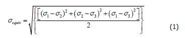
where σ1, σ2 and σ3-the principal stresses. σequiv - the equivalent stresses. The equivalent stresses are related to equivalent strains by the following relation:
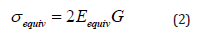
where G = E /(2(1+ ν)) is the shear modulus; E is Young’s modulus; ν is Poisson’s ratio.
Additional conditions of the contact problem
According to [7,11,12], the boundary contact problem is characterized by the presence of a contact zone of a known (stable) or unknown (unstable, variable) configuration. In this zone, there is no interpenetration of the surfaces of bodies, and the forces transferred because of contact cannot be tensile (considering the forces of surface adhesion in the contact zone, a certain level of “negative pressure” is allowed). According to the consequence of the general conservation law (the law of surface interactions), the contact forces on two contact surfaces must be equal in magnitude and multidirectional. In this case, forced contact can be carried out both with friction and without friction. As a result, the formulation of the boundary contact problem includes additional contact conditions and constraints, which can be described by the following equations, on the contact surface Sk [7,12].
On the general surface Sk of elements with conditional numbers 1 and 2, the following coupling conditions must be satisfied:

b) kinematic during adhesion (displacement of U in the same basis as the coordinates x)
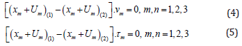
where νm, τm respectively, vectors components of the outer normal to contact surface and tangent to this surface. During slipping (with or without friction), condition (5) is not used [7,11,12].
Among the set conditions are:
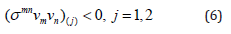
c) Negative values of normal components of contact forces
d) mutual non-penetration of bodies

Inequalities (6), (7) are the basis for the determination of the current contact surface configuration.
The force interaction of surfaces in the contact zone Sk can occur under conditions of adhesion or slippage. In the case of adhesion, that is, with
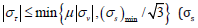
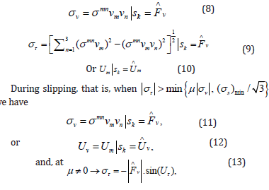
where

In the process of minimizing the target FEM functional, additional constraints (3)-(14) are usually taken into account by one of two methods: (PM) and LMM. PM is distinguished by its economy of memory and time resources and has become quite widespread when solving frictional contact problems. In turn, LMM is known for its accuracy [7,13]. However, it may lead to incorrect convergence of the solution. Considering the need to quickly solve contact problems that arise during the production and operation of power equipment, the PM was adopted to solve the considered problem. In contact problems, the penalty term includes the stiffness matrix of the contact surface. This matrix stems from the concept that one imaginary body penetrates another [11]. The stiffness matrix of the contact surface is added to the stiffness matrix of the contacting body, so that the incremental equation of the FE becomes;
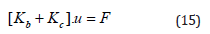
where: Kb is the stiffness matrix of contacting bodies; Kc- stiffness matrix of contact surface; u-displacement; F-force.
The magnitude of the contact surface is unknown [14], therefore its stiffness matrix, Kc, is a nonlinear term. The total load and displacement values are
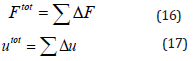
where: Ftot is the force vector; utot-displacement vector.
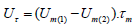
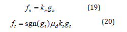
To derive the stiffness matrix, the contact zone (encompassing the contact surface) is divided into a series of contact elements. The element represents the interaction between the surface node of one body with the respective element face of the other body [13]. Given the nature of the numerical simulations only the sliding mode of friction will be presented. In this case, the tangential force acting at the contact surface equals the magnitude of the friction force, hence the first variation of the potential energy of a contact element is;

where: kn represents penalty terms used to express the relationship between the contact force and the penetrations along the normal direction; kt-penalty terms used to express the relationship between the contact force and the penetrations along the tangential direction; gn-penetration along the normal direction; gt-penetration along the tangential direction;
The FE software, for the penalty method, assumes that contact force along the normal direction is written as follows:

where: Kcont. is the contact stiffness, defined by real constant FKN (scale factor) for contact elements; xpenetr.-distance between two existing nodes on separate contact bodies; Fcont.-contact force. FE software automatically chooses the real constant FKN as a scale factor of the stiffness of the underlying elements.
The mechanical properties of the contact layer are described in terms of contact stiffness;
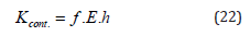
where f is the contact stiffness coefficient, 0.0001< f <100 ; E-is the Young’s modulus, МПа; h-is the characteristic linear size of the contact area.
To build the matrix of rigidity of the contact surface, the value of mutual penetration on the sealing surface of the flanges was taken to be close to the roughness height, namely 0.0025mm [7]. To overcome the influence of the meshing upon the results of the analysis and to improve the accuracy of the solution an adaptive solution will be used [13,15]. In FE software the desired accuracy of a solution can be achieved by means of adaptive and iterative analysis, whereby h-adaptive methodology is employed.
Analysis of the Result Obtained
As a result of the calculations, stresses were obtained in the
walls of the internal HP casing (on the external surface in the area
where the toroidal part of the casing mates with the horizontal
connector flange and in the meridional section of the casing) for the
K-330-23.5 turbine (Figure 2) is obtained. As a result, it has been
established that:
A. The SSS of the internal HP casings is three-dimensional,
and a complex deformation pattern is observed.
B. In general, the level of stresses in the walls of the casing is
small, but there are zones of increased stresses both on the external
surface in the area where the toroidal part of the casing mates with
the horizontal connector flange and on the internal surface in the
area where the steam inlet mates with the cylindrical part of the
casing.
C. Maximum deformations are experienced by the toroidal
part of the casings in the bridge between the steam supply pipes in
the radial direction.
Figure 2:Distribution of the equivalent stresses in the internal HP casing.

The nature of the distribution of contact pressure at different tightening forces corre-sponding to the initial tightening with a stress in the fastener of 300MPa and the stresses in the fastener, varied during the relaxation process, of 240MPa and 180 MPa in the middle and at the end of the overhaul period is shown in Figure 3.
Figure 3:Contact pressure level at the inner belt of the flange sealing surface under different tightening torques.

Conclusion
For the first time, an estimate is made of the SSS of the internal HP casing for K-330-23.5 steam turbine with the elastic deformation of the casings in a three-dimensional setting. This task was very relevant during the design and production of the elements of the specified turbine. The solution to the problem in a three-dimensional setting made it possible to assess the degree of influence of various geometric stress concentrators, such as steam pipes and horizontal connector flanges, and note that there is a pronounced difference in the nature of the distribution of the equivalent stresses in the region of transition of the cylindrical part of the casing to the toroidal one. A numerical study has been performed of the contact interaction between the flanges of the upper and lower halves of the casing in the elastic setting about the effect of the groove. It is shown that the guaranteed tightness of the flange connection for scheduled repair in 40 thousand hours of the operation of the turbine according to GOST 24278-91 is confirmed by the calculation data using the proposed improved methods; the flange connection does not open from the side of the inner belt. Based on the obtained results, the recommendations for improvement HPC inner case of K-330-23.5 turbine have been developed, which allow to get rid of several preventions of the negative phenomena caused by the high stresses in the structure. The proposed approaches and methods of calculation are implemented in the calculation practice of JSC “Turbulator” and used in the calculations and design of individual parts and assemblies of high and medium pressure turbine cylinders for supercritical parameters of steam Po=260÷300ata and To = 600 ͦC with a capacity of 600÷700MW.
References
- Zaitsev Borys, Shvetsov Viktor, Palkov Serhii, Hubskyi Oleksandr, Tatiana, et al. (2021) Investigation of the thermal strength of steam turbine diaphragms with reduction of axial dimensions. Journal of Mechanical Engineering 24(2): 37-49.
- Palkov Serhii, Shulzhenko Mykola (2019) Elastic stress-strain state of elements of the internal high-pressure casing for steam turbines. Journal of Mechanical Engineering 22(4): 32-40.
- Shulzhenko Nikolay, Gontarovskiy Pavel, Garmash N, Melezhik Irina (2018) Design forecasting of thermal strength and resource of steam turbine structural components. Journal of Mechanical Engineering 2(3): 38-46.
- Chernousenko O, Rindyuk D, Peshko V, Goryazhenko V (2018) Development of a technological approach to the control of turbine casings resource for supercritical steam parameters. Eastern-European Journal of Enterprise Technologies 2(1): 51-56.
- (1975) GOST 20700-75 Bolts, studs, nuts and washers for flanged and anchor connections, corks and yokes with medium temperature from 0 to 650 C. Specifications. Izdatelstvo standartov, Moscow, Russia, p. 23.
- McFarlane B (2017) Autodesk inventor exercises: For auto desk® inventor® and other feature-based modelling software, (1st edn), Routledge, UK, p. 424.
- Palkov I, Palkov S (2020) Stress strain state of steam turbine components under plastic deformation. Journal of Mechanical Engineering 23(4): 28-37.
- Wegst M, Wegst C (2019) Key to steel (Stahlschlussel). (25th edn), Verlag Stahlsclussel, Germany.
- Ugural A, Chung Y (2020) Mechanical engineering design. (3rd edn), CRC Press, USA, p. 852.
- Ugural AC, Fenster SK (2020) Advanced mechanics of materials and applied elasticity. (6th edn), New York, USA, p. 704.
- Benkhira El-Hassan, Fakhar Rachid, Mandyly Youssef (2019) Numerical approximation of a frictional contact problem in Elasto-plastcity based on the penalty approach. ZAMM Journal of Applied Mathematics and Mechanics 99(12): e201800300.
- Yu Chunxiao, Jing Dinghui, Fu Chang, Yang Yanfang (2021) A Kind of FM-BEM penalty function method for a 3D elastic frictional contact nonlinear system. Journal of Mathematics 2011: 1-11.
- Sofonea Mircea, Xiao Yi Bin (2021) Weak formulations of quasistatic frictional contact problems. Communications in Nonlinear Science and Numerical Simulation 101: 105888.
- Badia Santiago, Caicedo-Silva Manuel, Martín Alberto, Principe Javier (2021) A robust and scalable unfitted adaptive finite element framework for nonlinear solid mechanics. Computer Methods in Applied Mechanics and Engineering 386: 114093.
- Kalita P, Szafraniec P, Shillor M (2019) A frictional contact problem with wear diffusion. Z Angew Math Phys 70: 96.
© 2024 Serhii Palkov. This is an open access article distributed under the terms of the Creative Commons Attribution License , which permits unrestricted use, distribution, and build upon your work non-commercially.
Editor In Chief


.jpg)


Signup for Newsletter

Quick Links
 Editorial Board Registrations
 Submit your Article
 Refer a Friend
 Advertise With Us
Our Recent Edition

.jpg)


Top Editors


.jpg)


.bmp)
.jpg)
.png)
.jpg)


.jpg)


.png)

.png)


.png)


Financial Support

Sponsors

Latest e-Books

Latest Video

 a Creative Commons Attribution 4.0 International License. Based on a work at www.crimsonpublishers.com.
Best viewed in
a Creative Commons Attribution 4.0 International License. Based on a work at www.crimsonpublishers.com.
Best viewed in