
- About Us
- Information
-

The Author ensures that the research has been conducted responsibly and ethically with adherence to all relevant regulations. read more..
- For Authors
- For Reviewer
- Manuscript Guidelines
- Membership
- Publication Ethics
-
- Journals
- Reprints
- e-Books
- Videos
- Policies
- Contact Us
 COVID-19
- Submissions


Full Text
Evolutions in Mechanical Engineering
Mathematical Modeling of Hexafluoro Silicate Ammonia Desublimation
Jafarov MA1*, Yevdokymenko VO2, Kamenskyh DS2, Rustamov KA3 and Jafarov ZA4
1Baku State University, Azerbaijan
2Institute of Bioorganic Chemistry and Petrochemistry of the NASi of Ukraine, Ukraine
3TISA-Technology Industry Science Association, Istanbul, Turkey
4Azerbaijan Technical University, Azerbaijan
*Corresponding author:Jafarov MA, Baku State University, Azerbaijan
Submission: May 03, 2023;Published: July 06, 2023

ISSN 2640-9690 Volume4 Issue4
Abstract
The developed and software-implemented simplified three-dimensional mathematical model of the unsteady-state process of HFS desublimation into immersible vertical tanks with vertical finning is described. The study of regularities in the HFS desublimation process is performed by mathematical modeling.
Keywords:Ammonium hexafluorsilicate; Desublimation; Mathematical modeling; 3D modeling
Mini Review
In recent years, works aimed at studying and designing desublimation have become especially topical. The most promising way for the solution of similar problems is the mathematical modeling of unsteady state heat and mass transfer processes occurring during desublimation, as the experimental approach is expensive and takes a lot of time [1-3]. For the unsteady-state process of desublimation into vertical immersible tanks with smooth internal walls and horizontal finning, we developed the two-dimensional mathematical model, which does not use any empirical data and takes into account the motion of gas inside a tank, the desublimation of on the end walls of a tank, the elliptic shape of these walls, and the unsteady-state character of heat and mass transfer processes in contrast to the known mathematical models [4,5]. A non-stationary mathematical model of the process of desublimation of gaseous hexafluoro silicate into vertical cylindrical containers of a gas collector is presented. The mathematical modeling of the process considers the movement of gas inside the tanks, the ellipticity of the end walls of the tanks, and the mobility of the phase transition boundary. The possibilities of using experimental approaches are limited and require long-term and expensive experiments to be carried out on operating equipment or laboratory facilities, so one of the promising ways to solve the production problems described above is to create mathematical models of heat and mass transfer processes occurring sublimation and desublimation of HFS. This work is devoted to mathematical modeling of the process of desublimation of gaseous HFS into vertical transport containers. The existing mathematical models of the HPS desublimation process [6,7] are, as a rule, stationary or quasi-stationary. Their common disadvantages are the lack of consideration of heat transfer by convection and friction of the gaseous HFS against the desublimate layer during its movement along the heat exchange walls; desublimation on the end elliptical walls of heat exchange tanks; non stationarity of heat and mass transfer processes. In this regard, the purpose of this work was to create a non-stationary mathematical model of HPS desublimation, considering the presence of convection and HPS desublimation.
The mathematical model was developed taking into account the following assumptions: all the heat released during the phase transition is removed by the refrigerant through the vessel wall and the desublimate layer; gaseous HFS does not contain impurities; thermal processes inside the system under consideration can be described within the framework of the traditional theory of heat conduction; the gas flow before entering the container is considered to be isentropic, so the values of the total enthalpy and entropy are set on the cut; HFS desublimation on the upper elliptical wall of the container with a branch pipe is not taken into account, since it protrudes from the thermostat filled with refrigerant, the desublimation condition is set on the remaining boundaries with the wall; the gas is considered to be polytropic and the viscosity and thermal conductivity are neglected in the calculation of the gas phase. In mathematical modeling of the processes of heat and mass transfer occurring during the desublimation of gaseous HFS, a two-layer system was considered, where the first layer is the vessel wall material of constant thickness, and the second is the desublimate layer with a movable outer phase boundary. To calculate the heat flux, we used a one-dimensional differential equation of heat conduction for the vessel wall, a desublimate layer, and an integral law of conservation of energy to check the heat balance. The iteration-interpolation method [8] was used to numerically solve the heat conduction equations. The calculation of the temperature in the layer of solid HFS was carried out using a moving coordinate system associated with the wall-desublimate interface. While solving these equations, the temperature distribution in the wall-desublimate system was determined, the heat flux and the desublimation rate of ammonium hexafluoride silicate were calculated, after which the thickness of the solid phase layer formed was calculated.
The task of this work was to create a mathematical model of
the HFS desublimation process in a container with water cooling
of its cylindrical surface. Containers and “capacity” were chosen
as the object of modeling, because for these structures, there were
reliable experimental data on HFS desublimation. A feature of the
containers and “capacity” is their horizontal arrangement during
the desublimation process. Their inlet valve is in the upper part
of the front-end surface. The main task in building a model of the
desublimation process was to determine the degree of filling of
empty containers and the “capacity” of hexafluoro silicate in real
time. Determination of the analytical dependence of the uranium
hexafluoride condensation rate the calculation model was based on
the following assumptions:
A. The process of HFS condensation occurs mainly on the
cylindrical surface of the “tank” (container) irrigated with
cooling water. Condensation of HFS on the end walls of
the “tank” (container) due to weak heat exchange with the
surrounding air is insignificant.
B. The condensed HFS at each moment of time is a cylinder with
axial symmetry. The axial symmetry is due to the uniform
pressure distribution of the gaseous HFS inside the “tank”
(container), as well as a slight change in the temperature of the
cooling water as it flows laminar wave around the side wall of
the “tank” (container).
C. The temperature of the outer surface of the cylindrical wall of
the “tank” (container) is constant and equal to the temperature
of the cooling water at the considered moment of time. The
temperature of the inner wall of the condensed hexafluoro
silicate is equal to the temperature of the phase transition
(desublimation) of the HFS for the current pressure in the
“tank” (container).
D. The process of HFS desublimation in a “container” (container)
is quasi-static, i.e., the temperature distribution and the
thickness of the condensed HFS layer are linear and vary very
little with time.
Not only the stability and efficiency of the desublimation equipment, but also the environmental safety of production often depends on the correct organization of the thermal regimes of the process of desublimation of volatile substances in surface desublimators. Thus, when obtaining uranium hexafluoride (HFS) by fluorination of uranium oxides, HFS during desublimation can accumulate on certain areas of the surface of the apparatus, where the most effective conditions for this process are formed [9], which often leads to clogging of the apparatus or breakthrough of the uncondensed phase through the apparatus. As the solid product layer is formed, the free cross section of the desublimation apparatus decreases and accordingly, the gas velocity increases, the temperature of the desublimation surface changes, as well as the conditions for heat transfer from the desublimating product to the surface of the apparatus [4]. This leads to a change in the temperature of the desublimation surface, which can lead to a breakthrough of gaseous HPS through the apparatus, so gases after the fluorination stage containing HPS, oxygen and excess fluorine pass through two or more series-connected desublimators. In each subsequent apparatus along the gas flow, the desublimation surface increases. Therefore, it is relevant to determine the optimal conditions for the desublimation of HFS from a vapor-gas mixture in order to control the desublimation front in the apparatus and increase the degree of filling of the desublimator with a solid product due to its uniform distribution over the volume of the apparatus, eliminate product losses associated with inefficient operation of the desublimation surface, and prevent sudden clogging of the apparatus with solid HFS.
These problems can be solved using the mathematical model
of the desublimation process developed by us, which describes the
mass, thermal and hydrodynamic flows inside the apparatus. This
model makes it possible to determine:
a) mass flows of vapor-gas mixture and solid HFS inside the
apparatus (material flows).
b) coefficients of heat and mass transfer from the gas-vapor
mixture to the solid surface.
c) cooling time of the gas-vapor mixture from the initial
temperature to the HFS desublimation temperature.
d) speed and mass of HFS released from the gas flow into the
solid phase, per unit area of the desublimator.
e) change in heat and hydrodynamic flows inside the apparatus,
occurring due to an increase in the thickness of the product
layer on its walls in the process of desublimation.
Calculation of devices having an annular shape or the shape of flat plates is very complex, so let’s consider a mathematical model to determine the optimal thermal desublimation conditions for annular devices. Gas motion is described by a system of integral equations for the conservation of mass, momentum, and energy:
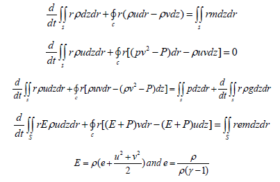
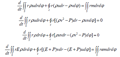
where C is an arbitrary closed contour that bounds the area S in the plane of variables z, r-cylindrical coordinate system, the origin of which is placed on the axis of symmetry in the input section; t is time; p is pressure; ρ-gas density; e-specific internal energy The gas flow parameters were considered in the cross sections formed by the radial and azimuthal axes at the top and bottom ends of vertical fins. The change in the calculate parameters of gas between these cross sections along the axial coordinate was assumed to be linear, thus making the considered computational region pseudo-threedimensional. In this case, the set of equations of gas dynamics is as follows:
Since only the temperature gradient formed in the direction perpendicular to the heat exchange surface was considered, a one-dimensional model was used to simulate thermal processes. Calculation of devices having an annular shape or the shape of flat plates is very complex, so let’s consider a mathematical model to determine the optimal thermal desublimation conditions for annular devices The formula for calculating the heat flux through the cylindrical surface of the HFS layer during the quasi-static heat transfer process [10] has the form:
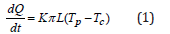
where: dQ is the amount of heat passing through the given surface during the time dt, J/(m2s); L is the length of the surface (the length of the cylindrical wall), m; Тс is the temperature of the cooled HFS layer, equal to the temperature of the irrigating water, ͦC; Тр is the phase equilibrium temperature at the HFS desublimation boundary in degrees Celsius, associated with the corresponding pressure Р in mm Hg. gaseous HFS in a “tank” (container) in the temperature range from 0 to 64 ͦC [2,3] by the formula:
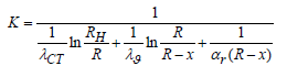
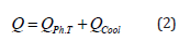
where λU is the thermal conductivity of the solid HFS, J/(s.m.K); λST is the thermal conductivity of the “container” (container) wall, J/(s.m.K); RN and R are the outer and inner radius of the tank wall, m; αG is the heat transfer coefficient at the phase transition boundary in J/(s.m2.K), obtained from experimental data. The amount of heat Q [5] passing through the surface of the “container” (container): QOHL is the amount of heat released during the cooling of the desublimated HFS when the temperature changes from the phase transition temperature to the temperature corresponding to the stationary state, J; QGAS is the amount of heat transferred to gaseous HPS during the phase transition, J. Since QGAS is insignificant (the heat capacity and density of gaseous HPS are much less than these characteristics of HPS in the solid phase), we will consider it equal to zero. Then:
To simplify the calculations, we transform the expression for QOCCL since the thickness of the desublimated HFS layer is small compared to the container diameter; therefore, the dependence of temperature T layer thickness x can be considered linear. Then, with an increase in the layer thickness by dx, the amount of heat QCOCL will be equal to half the amount of heat released during cooling of the layer with thickness dx from the temperature Тр to the temperature of the outer wall Тс. Thus, expression (2) will take the form:
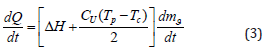
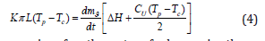
where ΔН is the specific heat of HPS desublimation, J/kg; dmg/ dt is the rate of change in the mass of desublimated HPS, kg/s; Cr is the specific heat capacity of solid HFS at constant pressure, J/(kg. K). Since the amount of heat given off by the system is equal to the amount of heat generated in the system, then, considering Eq. (1) and (3) can be written:
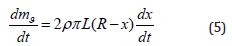
The expression for the rate of change in the mass of hexafluorosilicate can be written as the following differential equation:
Substituting (5) into (4) and expressing dx/dt, we obtain the main calculated differential equation:
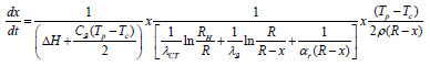
x thermal desublimation conditions for ring apparatuses
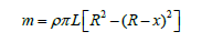
When solving equation (4) the fourth order Runge-Kutta numerical method [6] obtained the dependence of the HFS layer thickness on time: x=f(t). Knowing the layer thickness, it is possible to determine the mass of condensed HFS in the container using the formula:
The motion of gaseous HFS in the tank was two-dimensional axisymmetric and was described by a system of integral equations for the conservation of mass, momentum, and energy. This system of equations was reduced to a dimensionless form, the solution domain was normalized. For the numerical solution of the system of equations of gas dynamics, the classical SIMPLE method [11] on a moving grid was chosen, which has proven itself well for solving problems of calculating subsonic internal flows [12]. As a result, the dependencies of the change in the desublimate mass and the dimensionless desublimation rate on the process time were obtained (Figure 1).
Figure 1:Flow trajectories and fluid temperature.

At the next stage, the collector was calculated. At the initial moment, containers with some residual pressure are connected to the collector. In the process of filling them with desublimate, due to the increase in the thickness of the solid HFS layer, the thermal resistance of the vessel wall-desublimate layer system increases, the heat flow from the gaseous HFS to the refrigerant decreases, because of which the desublimation rate decreases and the pressure inside the container increases. The value of the temperature of the HFS phase transition from the gaseous state to the solid state depends on the pressure value. Temperature, in turn, affects the density, thermal conductivity, and heat capacity of solid HPS. At the moment when the pressure in the first tank reaches a critical value, the second tank, which is part of the collector, is connected, and so on in the same way until the entire volume of the first and then subsequent collector tanks is filled. The filled container is immediately cut off from the collector and replaced with an empty one. This algorithm has been implemented as an application package with a user-friendly interface. As a result, we have developed a two-dimensional non-stationary mathematical model of HPS desublimation in a reservoir consisting of several tanks, considering the presence of HPS convection and desublimation on the bottom wall of the tank, as well as the ellipticity of the upper and lower walls of the tank, which allows us to calculate a collector of any capacity, consisting of tanks of various types. The developed simplified three-dimensional mathematical model of flow trajectories and heat treatment desublimation was implemented as software Solid work (Figure 2).
Figure 2:Velocity and pressure distribution in the sublimator and DE sublimator.

References
- Martins MM, Vaz M, Zdanski PS (2018) A note on a derivative scheme for the finite volume method applied to incompressible viscous fluid. Continuum Mech Thermodyn 30: 943-952.
- Darwish M, Geahchan W, Moukalled F (2017) Fully implicit method for coupling multiblock meshes with nonmatching interface grids. Numer Heat Transfer 71(2): 109-132.
- Fang WZ, Gou JJ, Chen L, Tao WQ (2018) A multiblock lattice Boltzmann method for the thermal contact resistance at the interface of two solids. Appl Therm Eng 138: 122-132.
- Khorrami Z, Banihashem MA (2019) Improving multi-block sigma-coordinate for 3D simulation of sediment transport and steep slope bed evolution. Appl Math Modell 67: 378-398.
- Wang S, Nissen A, Kreiss G (2018) Convergence of finite difference methods for the wave equation in two space dimensions. Math Comput 87: 2737-2763.
- Hassanzadeh R, Tokgoz N (2017) Thermal-hydraulic characteristics of nanofluid flow in corrugated ducts. J Eng Thermophys 26(4): 498-513.
- Orlov AA, Tsimbalyuk AF, Malyugin RV, Leontieva DA, Kotelnikova AA (2018) Effect of tank geometry on its average performance. AIP Conf Proc 1938(1).
- Tigunova OO, Beiko NE, Kamenskyh DS, Tkachenko TV, Yevdokymenko VO, et al. (2016) Lignocellulosic biomass after explosive autohydrolysis as substrate for butanol. Biotechnologia Acta 9(4): 28-34.
- Fedin AS, Voroshilov FA, Kantaev AS, Ozherelyev OA (2013) Ammonium hexafluoro silicate sublimation research. Tomsk Polytechnical University News 323(3): 23-27.
- Daraoui N, Dufour P, Hammouri H, Hottot A (2010) Model predictive control during the primary drying stage of lyophilization. Control Engineering Practice 18(5): 483-494.
- HriberŠek M, Zadravec M, Časar Ž, Ravnik J (2018) The influence of the vial stopper on the flow and mass transfer conditions inside a vial. WIT Transactions on Engineering Sciences 120: 193-200.
- Ravnik J, GolobiČ I, Sitar A, Avanzo M, Irman Š, et al. (2018) Lyophilization model of mannitol water solution in a laboratory scale lyophilizer. Journal of Drug Delivery Science and Technology 45: 28-38.
© 2023 Jafarov MA. This is an open access article distributed under the terms of the Creative Commons Attribution License , which permits unrestricted use, distribution, and build upon your work non-commercially.
Editor In Chief


.jpg)


Signup for Newsletter

Quick Links
 Editorial Board Registrations
 Submit your Article
 Refer a Friend
 Advertise With Us
Our Recent Edition

.jpg)


Top Editors


.jpg)


.bmp)
.jpg)
.png)
.jpg)


.jpg)


.png)

.png)


.png)


Financial Support

Sponsors

Latest e-Books

Latest Video

 a Creative Commons Attribution 4.0 International License. Based on a work at www.crimsonpublishers.com.
Best viewed in
a Creative Commons Attribution 4.0 International License. Based on a work at www.crimsonpublishers.com.
Best viewed in