
- About Us
- Information
-

The Author ensures that the research has been conducted responsibly and ethically with adherence to all relevant regulations. read more..
- For Authors
- For Reviewer
- Manuscript Guidelines
- Membership
- Publication Ethics
-
- Journals
- Reprints
- e-Books
- Videos
- Policies
- Contact Us
 COVID-19
- Submissions


Full Text
Evolutions in Mechanical Engineering
Development of a Micro Sheet Hydroforming Setup to Produce Micro Cup Products
Fariborz Forouhandeh*
Department of Engineering, Shahrood Branch, Islamic Azad University, Shahrood, Iran
*Corresponding author:Fariborz Forouhandeh, Department of Engineering, Shahrood Branch, Islamic Azad University, Shahrood, Iran
Submission: June 10, 2023 ;Published: June 23, 2023

ISSN 2640-9690 Volume4 Issue4
Abstract
Micro forming is a very sensitive and applicable process to fabricate products with less than 1mm dimensions. Some challenges like gripping and tool design need more investigation. The sheet hydroforming method can be replaced instead of cup/deep drawing for fabrication of complex shape products. In this paper, research on micro sheet hydroforming work has been introduced and explained. A final element simulation has been carried out for deformation of a micro cup with 0.05mm thickness. A micro hydroforming setup has been designed and fabricated based on results of simulation. Result of FEM simulation has been good agreement in comparison with experiments by the setup.
Keywords:Sheet hydro forming; Tube hydro forming; Micro Hydroforming; Finite element simulation; Stainless steel (AISI-304)
Introduction
Hydroforming is a very suitable technology due to some advantages like high strength to weight ratio, better surface quality and good thickness distribution of products [1-3]. Miniature hydroforming and especially micro-Hydroforming are an area to form products with less than 0.05mm thickness and it needs controlled blank holding and smooth container to tolerate high fluid pressure [3,4]. Size effect is also a problem in micro forming processes [5-7]. There is some research regarding micro forming processes. Hirota K et al. [8] carried out micro-extrusion process with less than 50μm size. Kim DJ et al. [9] carried out Finite element simulation of micro-rolling. Yiping L et al. [10] carried out micro forging simulation. Emil Egerer et al. [11] carried out hot micro forming simulation along with experimental validation. Zhuang W et al. [12] carried out an experimental investigation about micro-tube hydroforming. The thickness of the tube was 30.4μm. Fu MW et al. [13] carried out experimental and simulation studies of micro blanking and deep drawing compound process using copper sheet material [13]. Hung J et al. [14] carried out an experimental study to produce micro-flow channels with 0.051mm thickness. In this paper Micro Sheet Hydroforming (MSHF) work carried by author has been introduced.
Simulation of micro sheet hydroforming process
In this part simulation of Micro sheet hydroforming Using package DEFORM-3D is explained [15].
Preprocessing for micro sheet hydroforming
The difficulty in producing micro-components is the design for its tools and dies. Therefore, a simulation study is very important to gain the know-how of the entire process well in advance before starting the actual manufacturing. Here the blank of 9mm is formed into the cup as shown in Figure 1. Stainless steel (AISI-304) is used as a work piece material and its properties are given in Table 1 [16-18]. Different simulations are performed and some of the results are discussed in this section. Material properties of this kind of stainless steel are very similar to a kind of CuBe2% [19]. Figure 1 shows the micro-forming blank, which is meshed with 1, 45,200 tetrahedral mesh elements. The blank diameter is calculated by the formula, as shown in Figure 2 [20]. CAD model of the required shape has been given in Figure 3. Initial design for micro sheet hydroforming has been shown in Figure 4. In this situation punch is cited above of the liquid and will push the fluid into the die cavity therefore friction value is very high and deformation load will be increased. Simulations were carried out for micro forming to study the different kinds of defects and specifically to calculate the starting load required to start the deformation. Also, the thickness distribution is plotted. Some kind of defects like thinning, tearing, wrinkling and high load requirement are observed and efforts were carried out to get the optimum deformation which would be free from defects.
Figure 1:Micro-forming meshed blank.

Figure 2:Formula to calculate Blank Diameter [20]. Where, d1= 5.8mm, d2= 6.3mm and s=1.52mm, therefore blank diameter = 8.54mm which can be taken as 9mm.

Figure 3:Geometry of microcap, all dimensions in mm.

Figure 4:Front view of punch, sheet and die cavity for simple micro sheet hydroforming (fluid pressure from upside) (first condition).

Table 1:Material data for micro-forming simulation.

Design modifications
Attempts have been done to minimize the thinning and high load requirements. Design modifications are done as shown in Figure 5. Instead of a die cavity the container is used which is provided with pressurized fluid. This pressurized fluid also acts as a cushion minimizing the defects like tearing and wrinkling. Second modification is done by changing the die profile radius which plays significant role for the proper deformation. Also, the cup forming operation is carried out by designing actual punch and here the punch movement is considered as an important factor [21].
Figure 5:Front view of punch, sheet and die cavity for micro hydro mechanical deep drawing (fluid pressure from downside) (second condition).

Simulation result
Figure 6 shows effective stress distribution in appropriate deformation under second condition with container and fluid pressure from downside. Area of flange is more than enough and secondary operation (cutting) is required. Figure 7 shows appropriate deformation with some permitted wrinkles under second condition. Figure 8 shows strain distribution in appropriate micro cup. Figure 9 shows damage distribution.
Figure 6:Effective stress distribution in micro cup (with flange without wrinkling).

Figure 7:Effective stress distribution in micro cup (with permitted wrinkling and small flange).

Figure 8:Strain distribution in appropriate micro cup.

Figure 9:Damage distribution (damage value: 0.00039).

Forces in sheet hydroforming
In cup drawing many different processes take place simultaneously. The punch pushes the sheet into the die (Figure 10). The sheet under the punch pulls the remaining sheet in flange under the blank holder plate. As the punch advances, the sheet in flange is pulled over the die profile radius into cup wall. In doing so the sheet in flange suffers circumferential compression, bends under tension into die profile radius, slides over die profile radius and then it unbends into cup wall. Also, the sheet on the punch profile radius bends under tension. All these processes add to tension in the cup wall. The maximum stress thus occurs at the punch profile radius. The total stress in the cup wall is due to the cumulative effect of the following processes taking place during deep drawing.
Figure 10:Stresses in sheet in cup drawing [4,5].

A. Drawing of flange under friction between the die and blank
holding plate.
B. Bending of sheet at the die profile radius.
C. Slipping of sheet into the cup wall.
D. Unbending the sheet into the cup wall.
E. Bending over punch profile radius (punch corner radius).
Total stress and forming load to start the deformation (punch force) for SHF can be calculated using equation no. 1 and 2 respectively [22,23]:
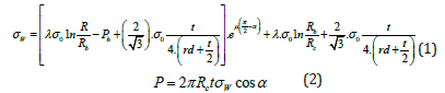
Where, σw: Stress in cup wall, P: Punch force, α: Angle between the punch axis and the cup wall, t: Thickness of cup wall, Rc: The mean radius of the cup at the section where σw is determined, Rb: The radius on flange where bending takes place, R: Current outer radius of flange, Ph: Hydrostatic or fluid pressure, σ0: Yielding stress, λ: Thickening factor which has value between 1 and 2/√3, rd: Die radius, μ: friction value.
Percent error should be calculated using [(measured-actual)/ actual] ×100 where the analytical result formula is taken as measured value and simulation result as actual one) [24]. Table 2 shows comparison between first condition (without container) and second condition (with container) for calculating total forming load by simulation. Also, Table 3 shows comparison between results of simulation and explained analysis about forming load of micro cup under micro sheet hydroforming. For analytical formula, the value of any data has been selected from table 3.5 and Rc(2.975≅3mm), Rb(3.17mm) and R(4mm), Ph(2MPa), λ(1.1), α(6.65°=0.037π radian) regarding geometry details obtained from figure 3.40 and t(0.05mm) have been selected to substitute in equations (1) and (2). It appears that in simple shape percent error is not very high. Figure 11 shows comparison of thickness distribution for micro sheet hydroforming in two methods. This study can also illustrate the advantage of design modification in the second condition (without die cavity).
Table 2:Comparison between first condition (without container) and second condition (with container).

Figure 11:Thickness distribution for micro sheet hydroforming.

Table 3:Comparison between results out of simulation and analysis.

Design and fabrication of a simple micro sheet hydroforming setup and experimental study
Based on concept of simulation results, a simple micro sheet hydroforming setup has been designed and developed to study the functionality of deformation of micro size sheet under hydro forming and evaluating of the defects. The thickness of the sheet is 0.05mm (less than 0.1mm) therefore it will be in the micro size category. Figures 12-14 show the detailed design of the setup. The setup has been fabricated for restriction of two plastic parts of the die and blank holder. A simple screw jack (1 ton capacity) provides force for punch moving from downside also punch load can be measured using one seated load cell above the jack as shown in Figure 12 & 15. Jack pushes the piston connected to the punch and punch will push fluid through the work piece and therefore work piece/sheet will be pushed inside of die. Figure 13 shows a closeup view of the die cavity. In this simple design two acrylic parts are in contact with each other. Fluid will come from downside and blank is already restricted between two in contact plates as shown in Figure 12 & 14. Acrylic material has been used for the die set as shown in Figure 14. Figure 15 shows detailed design of load cell to calculate total forming load of setup based on previous research [25-28]. Figure 16 shows developed micro sheet hydroforming setup.
Figure 12:Front view of the designed micro sheet hydro forming setup.

Figure 13:Close up view of die set of microcup.

Figure 14:Front view of the designed micro sheet hydro forming setup..

Figure 15:Seated load cell along with strain gauge for measuring the punch load.

Figure 16:Developed simple micro sheet hydroforming setup.

Explanations of the parts in Figure 16:
a) Upper plate for restriction of up movement of the die set
b) Middle plate for restriction of side movement of the die set
c) Lower plate for restriction of down movement of the die set
d) Legs (Diameter: 25mm)
e) Screw jack for providing the deformation force along with load
cell.
f) Die set of micro sheet hydroforming
The maximum forming load by the simulation has been 1.66KN as shown in Table 2. This value has been obtained around 1.50KN from experimental study using load cell along with relevant strain gage after calibration [29,30]. Therefore, the result of FEM simulation has been good agreement with experimental study.
Conclusion
In this paper, research on micro sheet hydroforming work has been introduced and explained. A final element simulation has been carried out for deformation of a micro cup with 0.05mm thickness. The process has been simulated for two different conditions (with and without die cavity). Result of simulation and analytical study has been compared. A micro hydroforming setup has been designed and fabricated based on results of simulation. Result of FEM simulation has been good agreement in comparison with experiments by the setup.
References
- Forouhandeh F, Kumar S, Ojha SN (2013) Recent development in micro hydroforming. Advances in Mechanical Engineering 2013: 1-14.
- Forouhandeh F (2013) Development of a sheet hydroforming process for metals and alloys. Department of Mechanical Engineering, Indian Institute of Technology, Banaras Hindu University, India, pp. 175-188.
- Hosseinzade M, Mostajeran H, Bakhshi-Jooybari M, Gorji A, Norouzi S, et al. (2009) Novel combined standard hydromechanical sheet hydroforming process. IMechE Journal of Engineering Manufacture 224(3): 447-457.
- Tung-Sheng Y (2008) Finite element analysis of square cup deep drawing of pure titanium metal sheet at elevated temperatures. Advanced Design and Manufacture to Gain a Competitive Edge 1: 33-42.
- Forouhandeh F, Kumar S (2013) Miniature hydroforming process, proceeding of national symposium on miniature manufacturing in 21st Department of Mechanical Engineering, Indian Institute of Technology (BHU), India, pp. 231-246.
- Banabic D (2009) Sheet metal forming processes, pp. 18-21.
- Forouhandeh F, Kumar S, Ojha SN (2015) Recent development of hydroforming: A review. International Journal of advanced Manufacturing systems 15(2): 27-36.
- Hirota K (2007) Fabrication of micro-billet by sheet extrusion. Journal of Materials Processing Technology 191(1-3): 283-287.
- Kim DJ, Ku TW, Kang BS (2002) Finite element analysis of micro-rolling using grain and grain boundary elements. Journal of Materials Processing Technology 130-131: 130-461.
- Yiping L (2002) Application of micro forging to SiCN MEMS fabrication. Sensors and Actuators 95(2-3): 143-151.
- Egerer E, Engel U (2004) Process characterization and material flow in micro forming at elevated temperatures. Journal of Manufacturing Processing 6(1): 1-6.
- Zhuang W, Wang S, Lin J, Balint D, Hart Ch (2012) Experimental and numerical investigation of localized thinning in hydroforming of micro-tubes. European J Mech A/Solids 31(1): 67-76.
- Fu MW, Yang B, Chan WL (2012) Experimental and simulation studies of micro blanking and deep drawing compound process using copper sheet. Journal of Materials Processing Technology 213(1): 101-110.
- Hung J, Chih C (2012) Fabrication of micro-flow channels for metallic bipolar plates by a high-pressure hydroforming apparatus. Journal of Power Sources 206: 179-184.
- (2014) DEFORM-3D (18) user’s manual, Version 10, Scientific Forming Technologies Corporation. Columbus, Ohio, USA, pp. 52-201.
- Chatale AK, Gupta RC (2005) Product design and manufacturing, (7th edn), PHI Publication, New Delhi, India, p. 628.
- Forouhandeh F, Kumar S, Ojha SN, Parkash TO (2012) Modeling of sheet hydroforming of CP Titanium for semispherical cup shape product. International Journal of Modeling and Simulation in Design and Manufacturing 3(1-2): 147-156.
- Underwood EE (1970) Quantitative stereology. Addison-Wesley Publishing Co, USA, pp. 37-47.
- (2000) ASM Aerospace Specification Metals, USA, pp. 800-802.
- Lange K (1996) Handbook of metal forming, SME Publishers, USA, p. 1172.
- Forouhandeh F, Kumar S, Ojha SN, Nahak B (2012) Development of a sheet hydro forming setup and product characterization. 4th International and 25th all India Manufacturing Technology, Design and Research Conference, Kolkata, India, pp. 696-700.
- Juneja BL (2006) Fundamental of metal forming processes. New Age International Publication, India, p. 424.
- Odenberger Eva-Lis (2009) Concepts for hot sheet metal forming of titanium alloys. Doctoral thesis, Lulea University of Technology, Sweden, pp. 160-163.
- Forouhandeh F (2015) An optimization of hot forging process of Ti-6Al-4V for non-isothermal condition. Journal of Scientific Research and Reports 8(6): 1-10.
- Forouhandeh F (2004) Modeling of forging process for titanium alloys and its application to manufacturing a part (Unpublished Master Thesis). Dept of Mech Eng, Iran University of science and technology, Iran, pp. 35-47.
- Forouhandeh F (2017) Metal forming by sheet hydroforming method. Azad university, Shahrood Branch Publication, Iran, pp. 110-115.
- Sujoy H, Gazder AA, Carman A, Pereloma EV (2010) Effect of cold rolling on as-Ecap interstitial free steel. Metallurgical and Materials Transactions 42(5): 1334-1348.
- Abedrabbo N, Zampaloni MA, Pourboghrat F (2005) Wrinkling control in aluminum sheet hydroforming, International Journal of Mechanical Science 43: 333-358.
- Window AL, Hollister GS (2000) Strain gauge technology. (2nd edn), Applied Science Publishers, Basel, Switzerland, p. 358.
- Forouhandeh F, Kumar S, Ojha SN, Parkash TO (2013) A generative CAPP system for sheet hydroforming of CP titanium. International Journal of Emerging technology and Advanced Engineering 3(6): 644-659.
© 2023 Fariborz Forouhandeh. This is an open access article distributed under the terms of the Creative Commons Attribution License , which permits unrestricted use, distribution, and build upon your work non-commercially.
Editor In Chief


.jpg)


Signup for Newsletter

Quick Links
 Editorial Board Registrations
 Submit your Article
 Refer a Friend
 Advertise With Us
Our Recent Edition

.jpg)


Top Editors


.jpg)


.bmp)
.jpg)
.png)
.jpg)


.jpg)


.png)

.png)


.png)


Financial Support

Sponsors

Latest e-Books

Latest Video

 a Creative Commons Attribution 4.0 International License. Based on a work at www.crimsonpublishers.com.
Best viewed in
a Creative Commons Attribution 4.0 International License. Based on a work at www.crimsonpublishers.com.
Best viewed in