
- About Us
- Information
-

The Author ensures that the research has been conducted responsibly and ethically with adherence to all relevant regulations. read more..
- For Authors
- For Reviewer
- Manuscript Guidelines
- Membership
- Publication Ethics
-
- Journals
- Reprints
- e-Books
- Videos
- Policies
- Contact Us
 COVID-19
- Submissions


Full Text
Evolutions in Mechanical Engineering
Experimental Investigation of Gamma Stirling Engine Coupling to Convert Thermal to Cooling Energy in Different Laboratory Conditions
Sareh Daneshgar1 and Rahim Zahedi2*
1Faculty of Electrical and Computer Engineering, Tabriz University, Iran
2Department of Renewable Energy and Environmental Engineering, University of Tehran, Iran
*Corresponding author:Rahim Zahedi, Department of Renewable energy and Environmental Engineering, University of Tehran, Iran
Submission: April 22, 2022;Published: May 23, 2022

ISSN 2640-9690 Volume4 Issue2
Abstract
The main aim of this research is to experimentally investigate the two coupled identical ST500 gammatype Stirling engines and convert thermal energy to cooling energy. Using a new structure and two coupled Stirling engines at different temperatures and pressures and use of biomass fuel within the 4-8 bar average pressure range of the first engine hot source, the 1-4 bar average+ pressure range of the second engine cold source, and Stirling hot engine temperature range of 480-580 ºC, the effective cooling is obtained in the cold engine. In doing tests, attempts were made to reach lower than 9 percent error results in different parts of engine, including insulation, fluid leakage, belt loosing, and measurement devices. According to the obtained results, 8 bars increase in the average pressure range of the gas in the first engine hot source, a 1 bar reduction in the average pressure range of the gas in the second engine cold source, the increased temperature of the hot source up to 580 ºC, and the use of the light operating fluid such as helium will affect the generation of cooling up to-16ºC.
Keywords: Couple; Power supply; Gamma; Stirling; Cooling; Biomass
Introduction
Stirling engine
Stirling engine is one of the hot air engines, in which the gas due to heating, tends to get expanded, and due to cold, tends to get contracted, and this consecutive heating and cold of the engine leads to movement of pistons and crank mechanism. Nowadays, different technologies for the development of using renewable energies are used. One of these technologies, which today is really interesting is utilizing a heat engine called Stirling engine [1]. Stirling engine is an external combustion engine and is highly flexible in terms of using different energy sources and can convert the thermal energy in the renewable sources into mechanical and electrical energy [2].
Stirling motor is one of the hot air engines, which like other types of heat engines, by using heat exchange between a hot source and a cold one, can produce mechanical and electrical work. Heat enters the engine at high temperature. Part of that converts to mechanical or electrical work and the rest is ejected from the motor at lower temperatures [3]. Stirling engine in terms of performance, is simple and has good torque, and if used in reverse, it can be an alternative for the refrigeration cycles. Today, introduction of new alloys and sealing materials, as well as the use of software and advanced computers that facilitate the accurate and complex calculations, will accelerate the evolution of this engine. If optimization of the current engines for the reduction of fuel, emissions and noises do not see the international standards of environmental organizations, without any hesitation we should go for Stirling engines [4].
Types of stirling engines
Stirling engines have been developed over the years and various designs of this type of engine have been developed. Different types of Stirling engines are known as Alpha, Beta, Gamma and Free Piston. The principles of thermodynamics are the same for all of them, and the main difference is in how the different components of the engine are placed next to each other. All Stirling engines have five control volumes, which are compaction chamber, air conditioner, recovery, heating and expansion chamber [5].
Alpha type engine
The Alpha engine has two separate cylinders for compression and expansion spaces, and a piston in each cylinder. Two separate cylinders are connected by a heat sink and an interface pipe. The hot cylinder is placed next to the hot source and the cold cylinder is placed next to the cold source. These types of engines are conceptually the simplest combination of Stirling engines. In the alpha engine, the volume of each of the engine’s hot and cold chambers is determined using the hot and cold pistons, whose motion is controlled, respectively. Figure 1 shows the schematic of the Stirling engine with alpha structure along with the heat inlet and its heat sink, in which the movement of the pistons is controlled by the rotation of the crankshaft and the four processes expressed in each 90 degrees of rotation of the crankshaft. To be. In this method, both hot and cold pistons need to be sealed; This may not be a problem for the cold side piston, but complete sealing of the hot side piston due to the different thermal expansion coefficients of the piston and cylinder wall will be a problem, which is one of the design complexities of this structure [6].
Figure 1:Schematic of Alpha type Stirling engine.

Beta type engine
Robert Stirling was invented as the first and oldest Stirling engine with a beta structure. In a beta engine, the hot side piston is removed and replaced by a cylindrical piece called a displacer between the hot and cold chambers. In this case, due to the removal of the hot piston, the sealing problem around the piston disappears [7]. Schematic of beta type Stirling engine is shown in Figure 2.
Figure 2: Schematic of beta type Stirling engine.

Gamma type engine
The Gamma-type Stirling engine is structurally similar to the beta engine, except that the piston is located in a separate cylinder relative to the displacement. The Gamma Stirling engine has a lower compression ratio than the Alpha and Beta models, but because only its power piston needs to be sealed and the cylinders are separate, it has the simplest mechanical arrangement among other Stirling engines [8]. Schematic of gamma type Stirling engine is shown in Figure 3.
Figure 3: Schematic of gamma type Stirling engine.

Free piston engine
This type of engine produces power from the reciprocating motion of the piston and does not actually require a flywheel or crankshaft; For this reason, they do not have problems with balance and bearing or bearing failure. In addition, due to its smaller volume and weight than other types, it is easier to install them in different places such as solar dishes. Due to the lack of flywheels in open-piston engines, they use a plate spring or oscillating beam to reverse the piston, or to connect several free-piston engines to each other as shown in Figure 4 [9].
Figure 4: Schematic of free piston type Stirling engine

In the field of analysis and modeling of the Stirling engine, Schmidt [10] performed the first thermodynamic analysis. In this model, the temperature of the compaction chamber with the cooler and the temperature of the expansion chamber with the heater are considered equal and constant, and the isothermal analysis is presented. Urieli and Berchowitz [11] perfected the theory of adiabatic. In this model, the differential equations governing the chambers are solved numerically by Range Kota method and in order to predict the numerical solution, the effects of the frictional pressure drop of the gas flow
In the recovery, the effect of non-ideal recovery in the recovery and correction of the gas temperature inside the heaters and coolers is considered and a method called simple is presented. Finkelstein [12] considered the compaction and expansion chambers to be adiabatic. In this analysis, the gas temperature changes during the compaction and expansion process, and the heater and cooler are considered to be at the same temperature.
Prakash et al. [13] investigated the effect of increasing efficiency due to the use of Stirling motor in the combined cycle of ironing and Stirling. The Stirling engine supplies the electric charge required by the vehicle in question by using a temperature difference of 75 °C between hot and cold sources. This temperature difference is supplied from the wasted energy by the car drainage system and its amount is 950 watts. In this design, the Stirling engine rotates the car alternator instead of the engine belt.
Zia Basharhagh and Mahmoudi [14] conducted studies in the field of beta-type Stirling engine, and based on the obtained results showed that by changing the operating gas and using hydrogen gas instead of gas helium, the amount of heat output and exhaust capacity G engine decreases while engine efficiency increases. In case of T, the heat output of T is high to the motor Helium would be a good option. Another result of this research is that the energy flow in the Stirling engine recovery is almost 5 times more than the heater and 6 times more than the cooler. Also, as the diameter of the Stirling engine piston increases, the power decreases while the efficiency of the Stirling engine increases. Valenti et al. [15] evaluated a unit of simultaneous production of heating and electricity with the primary actuator of the Stirling engine to generate electrical power at different operating pressures of the engine in a laboratory and numerical manner.
Karami and Sayadi [16] to optimize the capacity of the threestroke simultaneous production system with the Stirling engine for four different climates of Iran with the help of three goals, saving energy consumption, reducing emissions and saving total annual costs they have paid.
Houshang et al. [17,18] in their research to improve the control parameters of gas displacement in Stirling engine solar to increase efficiency as well as improve gas displacement control parameters including amplitude, phase and frequency of Stirling engine; In such a way that the thermal efficiency and production capacity of the engine increase. In order to ensure the mathematical model calculations, an experiment on a gamma-type Stirling engine was designed and performed using a third-order thermodynamic analysis code, during which the absolute fluid pressure, crankshaft angle and velocity were read and recorded instantly.
Also, the engine output power was measured using a generator and the results of the mathematical model were compared with the measured values under the same test conditions and its performance was ensured. The average error of mathematical and experimental modeling was shown to be about 10%. Amarloo et al. [19] performed thermodynamic analysis of the performance parameters of the new three-cylinder structure of the Stirling engine and its modeling in the industrial analytical software of JT Suite. The results of the analysis showed that increasing the rotational speed was not suitable for increasing engine performance and reduced engine efficiency.
Demirci et al. [20] used a gamma-type Stirling engine to generate heat and electricity on a small scale at a time, and at pressures of less than 1MPa the engine output power was compared in vitro by Schmidt analysis. Chahartaghi and Sheikhi [21] studied the simultaneous modeling of heating and electricity with the primary actuator of the Stirling beta engine from the perspective of fuel consumption with non-ideal adiabatic analysis.
Jahani Chaldee et al. [22] designed a Stirling engine to generate electricity, heating and cooling in a residential area with a different climate. The engine used is alpha type and the system is simulated in Jiti Suite software. According to the results, the maximum efficiency was between 79 and 88% in different climatic conditions.
The designed system reduced air pollution by reducing NOX and CO2, CO showed leakage of this system at low pressures to a lesser extent. Francisco Callis et al. [23] performed the optimization strategy of a combined cooling, heat and power system for an engine in a precise numerical analysis and found that the system’s optimal capacity was less than the actual design.
L Brin et al. [24] examined the overall performance of the refrigerator for the Stirling pair heat engine and the amount of work related to the final cooling with respect to construction effects and parameters such as temperature ratio for the engine and its density.
Ansari Nasab et al. [25] Combining Stirling engine with molten carbonate fuel cell, gas turbine for simultaneous production of electricity, heating and cold Examined the sensitivity and finally proposed three strategies to eliminate unnecessary costs that have improved system performance. Dai et al [26] investigated the Stirling engine process using the finite time thermodynamics and the hypothesis of uniform temperature distribution, analysis and the effect of various parameters and their limitations.
Katoli et al. [27] simulated and experimentally evaluated a stirling refrigerator unit to convert electrical-mechanical energy into cooling energy experimentally and the effects of fluid pressure and alternator power for cooling. Sowale et al. [28] have experimentally investigated a single gamma-type Stirling engine for cooling production using different gases. The results were obtained at a temperature of about -23 °C using the working fluid of the air and at a temperature of about -21 °C with helium gas. The results showed that increasing the power of the power supply, medium gas pressure, time of turning on the power supply and the use of light operating fluid such as air, helium will be effective in producing cooling.
This research is written from a single gamma-type Stirling engine and the use of a power supply to generate cooling, which is experimentally used in a new structure using a couple of ST500 gamma-type Stirling engines and energy conversion. Heat to mechanical energy to produce cooling by helium operating fluid in the medium pressure range of the first engine hot source 4 to 8 times and the average cold source pressure range of the second engine 1 to 4 times and the temperature range of the Stirling hot engine 480 to 580 °C can be cooled effectively on cold engine. The start of the first Stirling engine was performed experimentally using the combustion of biomass resources and the heat from the combustion of agricultural materials and wastes was transferred to the first Stirling engine and the engine started and started the second Stirling engine and produced cooling. Cooling below zero degrees Celsius can be achieved by increasing the thermal energy to 580 °C and increasing the supply pressure of the hot Stirling engine fluid by up to 8 times and decreasing the supply pressure of the cold engine fluid by up to 1 time. Generating cooling from renewable sources, in addition to environmental impacts, also makes the future of energy safer. According to the research, the production of cooling was a new method and it has not been done yet and with less error and more accuracy, more accurate results were obtained and in a laboratory sample of Stirling ST500 type gamma motor, for cooling application in various industries Automotive is recommended.
In summary, the objectives of this research were to design and build a heat chamber with biomass fuel for high temperature source and mechanical power generation by the first Stirling engine and finally to produce cooling by the second Stirling engine. During the experiments, the values of temperature, efficiency, power, pressure due to different temperatures in heating and cooling of the Stirling Gamma ST500 engine were measured using a test engine reader and Adam software and the results were compared with previous research, comparison and validation based on Nlog code is Done.
Methodology
Nlog code
The Nlog code is written by the MATLAB program and is used for thermodynamic analysis of the Stirling engine, and is a Stirling engine cycle analysis code that uses third-order equations. This code calculates the heat output and output power of the Stirling engine.
Geometric characteristics of all gas transmission channels, pipes and expansion chambers and density Geometry of connections between the moving parts of the engine The initial pressure of the engine and the initial temperatures at any point of the heat exchanger wall temperature which is considered constant over time. Nlog code divides all gas channels and pipes in the engine into control volumes and divides the dynamics and thermodynamic parameters for each control volume by solving continuity equations, momentum and determines energy. Using this structure, cooling can be generated directly from heat from renewable or non-renewable sources. The results obtained for the production of cooling were compared using the Nlog code previously validated by the authors in valid articles [17,18].
Mathematical modeling
In this research, a third-order thermodynamic dynamic model is used, which can be used to estimate the instantaneous speed of the engine in terms of time by estimating the variables of the operating fluid state of the engine, and to estimate the final efficiency and power output of the engine. In this dynamic-thermodynamic model, first the various chambers of the Stirling engine, including heating, cooling, recovery, etc. in the form of volume - controls with heat exchange, work and mass with its environment and also with the volume - controls Is considered adjacent. Heat transfer surface, heat transfer coefficients and thermal conductivity are effective in both heat receiving and dissipation processes. The thermal conductivity is much larger than the displacement heat transfer coefficient and therefore the resistance conduction heat was discarded and only heat transfer was considered as a limiting factor for heat absorption and dissipation. Regarding the recovery, the limitation of the thermal conductivity of the recovery is ignored. In order to investigate the effect of pressure drop due to fluid motion, fluid pressure at all points of each volume-control is considered the same and different from adjacent sections. Having the geometry, dynamic characteristics and wall temperature of hot and cold heat sources for the engine, fluid pressure drop coefficient and heat transfer coefficients are calculated through experimental relationships.
Thermodynamic relations
The principles of thermodynamics are the same for all Stirling engine structures, and there is a fundamental difference in how the various components are placed next to each other [29].
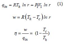
In the above relations, qin is the amount of heat received and is the productive work in joules (J) in an ideal Stirling cycle. Cold source in Kelvin (K) is the ratio of engine density, which is the ratio of the maximum volume of the system to its minimum volume, P1, V, and the pressure and volume in Pascal and cubic meters, respectively.
Dynamic relationships governing the model
In this research, a thermodynamic dynamic model that was previously written and validated for the heating mode of the Stirling engine was used [17]. One of the advantages of using the Stirling engine is the ability to reverse the duty cycle; Therefore, by changing the code pattern, it can be used to generate cooling. Validation of cooling code and cooling production in laboratory using two stirling ST500 engines of gamma type in research and development company Iran Khodro was performed experimentally for the first time and the results were analyzed. The kinematic parameters of the engine are shown in Figure 5.
Figure 5: Engine kinematic parameters ST500.

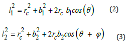
Parameters of φ, C1, C2, d , l1, l2, rc and a1 to a3 are structural parameters of the engine and have a fixed value. Equations 2 and 3 relate these parameters to b1 and b2 (the vertical distance of the Gajn pin at any moment to the direction of the crankshaft).
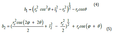
By solving the above equations for b1, b2 they are expressed as functions of the crank angle shown in Equations 4 and 5 [30].
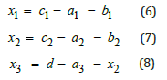
Therefore x (length of compaction chamber), x (length of hot chamber) and x (length of cold chamber) are obtained in terms of the crankshaft angle shown in Equations 6 to 8.
The derivatives of x1 , x2 relative to the crankshaft angle are also shown in Equations 9 and 10. These relations will be used in the dynamic relations calculation section.
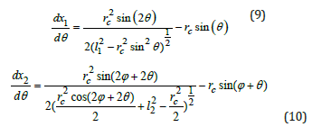
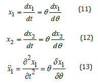
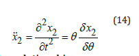
The first derivatives x1 , x2 which represent the velocity of the moving parts of the engine, are calculated using equations 11 and 12, and the second derivatives, which represent their acceleration, are calculated from equations 13 and 14 according to the rules of chain derivatives.
Model of kinetics relationships
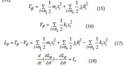
First, we have to find a differential equation that solves the speed and angle of the crankshaft moments and for this purpose the Lagrange dynamic method is used. The general form of Lagrange equations is shown in Equations 15 to 18. The sum will be Vθ and the sum of the potential energies of the components in the variable Tθ The kinetic energies of all the moving parts of the motor will be included in the variable. Lagrange is obtained by subtracting the total kinetic energy from the total potential energy, and finally, by placing the Lagrange in the principal Lagrange equation (Equation 18) and the necessary derivatives, the dynamic differential equation of the Stirling engine is obtained. θ in the Lagrange equation represents the amount of equivalent torque applied to the engine crankshaft, while I represents the variable of the crankshaft angle [31].
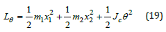
According to the number of variables considered, Lagrangian is obtained as Equation 19.
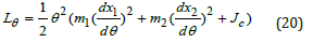
By placing the relations 11 and 12 in Equation 19, Equation 20 is obtained.
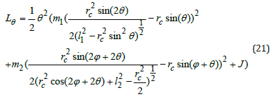
The calculated derivatives in Equations 9 and 10 are placed in Equation 20, and Lagrangin is obtained in terms of crankshaft angle and crankshaft angle velocity according to Equation 21.
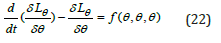
Therefore, if the derivatives of the Lagrange equation are applied to the Lagrangin, one unit is added to the degree of the derivative in the equations and the left part of the Lagrange equation becomes a function of angle, velocity and acceleration of the crankshaft to the form of Equation 22.
The Stirling engine used in this research
The studies performed in this study were performed on the ST- 500 engine available at the Iran Khodro Engine Research Center (or Peko), the technical specifications of which are shown in Table 1. The exterior of the engine is shown in Figure 6. In the form of the main parts of the engine, including the heater, cooler, exhaust, flywheel and piston housing are discarded [17].
Table 1:Stirling engine ST500 specifications.

Figure 6:Exterior view of Stirling engine ST-500.

Some parts of the Stirling engine such as heaters, water coolers and coolers can be seen in Figures 7 and 8.
Figure 7:Stirling engine heater with recovery.

Figure 8:Stirling engine coolant and fluid passage ducts.

Influential parameters in the experiment
A. Geometric characteristics of gas transmission channels,
pipes and expansion and compression guards
B. Geometry of connections between moving parts of the
engine
C. Initial engine pressure and initial temperature anywhere
in the engine
D. Heat exchanger wall temperature
E. Gas used in hot and cold source
F. Material of regenerative
Specifications of the regenerative used in the Stirling engine are shown in table 2.
Table 2:Specifications of the regenerative used in the Stirling engine [32].

Measure the belt loss before the test
In order to be accurate in the tests, the losses in the belt must be measured. The belt is used to transfer power from the hot engine to the cooling engine, and if the loss rate is more than a certain limit, the test error increases and the results are not reliable. For this reason, the losses in the belt should not exceed the specified limit. The specifications of the hot engine, alternator and Stirling engine flywheels along with their period are given in Table 3
As can be seen from the experimental results in Table 3, the belt error percentage is less than 9% and therefore. It can be said that the existing belt has a good power transmission [28].
Table 3:Specifications of alternator and two Stirling engines.

Test steps
The experiments were performed in the following three steps:
A. Evaluation of the results of a single Stirling motor for
cooling production using an air-powered fluid power supply at
520.8 watts and a working pressure of 3 times in 10 minutes
B. Evaluation of the results of a single Stirling engine for
cooling production using a power supply with helium gas at
a capacity of 420 watts and a working pressure of 6 times in 10
minutes and validation with previous research
C. Experimental study of coupling Stirling engine for cooling
production by receiving heat energy from heat source for the power
of the first Stirling engine and generating cooling with the second
Stirling engine using helium operating fluid and validation by
previous research.
Test for air-cooled cooling engine
Figure 9:Gamma-type Stirling engine ST500 schema.

Figure 9 Schematic of Gamma Stirling engine for cooling production. In Figure 10, the alternator was connected to a power supply (generator) and used for the initial release of the motor. The alternator was also connected to the flywheel using a belt. When the power supply is turned on, the alternator rotates and power is transmitted to the flywheel by a belt. In this case, according to the stirling cycle, the heating part of the device cools down and the temperature drops below zero degrees after a few short minutes. Copper pipes have been used to measure the heat transfer of the cold section. To measure the amount of heat transfer, water first flows into the copper pipes by a pump. The effluent was then collected in an insulated chamber. By measuring the water discharge from the copper pipes as well as measuring the temperature of the inlet and outlet water of the copper pipes, the amount of heat transfer in the heating section of the device was obtained according to Formula 23.
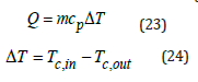
Figure 10:Power supply for power generation.

The actual view of the Stirling Gamma engine with insulation is shown in Figure 11. Initially, the Stirling engine was started using a power supply in laboratory conditions at different power, pressure and temperatures. For accuracy in experiments, ambient temperature, discharge water discharge from copper pipes were considered constant and equal, and for better comparison of results, the input power was confirmed by the alternator power supply in each experiment. In order to examine and compare more accurately, experiments were performed for different time intervals at different pressures, power and gases, and the production cooling temperature was calculated at each stage.
Figure 11:Gamma Stirling engine type ST500 with insulation to produce cooling.

Table 4 does not show the initial conditions for the four different experiments performed on the Stirling engine to generate cooling using air gas. In these experiments, the air pressure of the operating fluid was 3 times and the dynamo power was considered to be constant 520.8. Experiments 1, 2, 3, and 4 were performed over a period of 2 to 10 minutes. For all four flow tests, the discharge of water out of copper pipes was considered constant and equal. To better compare the results, the input power was fixed by the power supply. The voltage and current of the power supply were 31 volts and 17 amps, respectively, and the ambient temperature in all four experiments was constant and the temperature was T4, T and 25 °C. The temperature of the inlet and outlet parts of the copper pipes at the top and bottom of the cold part of the temperature reader T was measured. Finally, with increasing dynamo power and gas pressure, the temperature of 1 T of the cooling produced reached about -23 degrees Celsius. Figures 12 and 13 show the cooling output using a single Stirling Gamma ST 500 engine.
Table 4:Different laboratory conditions for cooling production [28].

Figure 12:Cooling output by using a gamma-ray stirling engine ST500.

Figure 13:Demonstration of cooling production at the output of the Gamma Stirling engine with insulation.

Figure 14 does not show the tail-time diagram for the six experiments performed at pressures of 3 and 6 bar and a power of 200 to 520.8 watts. As shown, when the power supply is turned on, the temperature of the heating part of the device decreases, and finally, after a certain period of time and increasing the power of the alternator and gas pressure, the temperature of the cold part of the engine Stirling will be in the form of Figure 12 and the temperature of the cold part T1 will reach about -23 degrees Celsius.
Figure 14:Temperature-time diagram for air gas experiments at different pressures for the Stirling engine in cooling mode [28].

Test for cooling engine using helium gas
Table 5 shows the initial conditions for the four different experiments performed on the Stirling engine to generate cooling using helium gas. In these experiments, the pressure of the working fluid was 6 times, the power of the alternator was 420 watts at 3 and 4 times for 2 to 10 minutes. For each of the discharge tests, the water discharge from the copper pipes was considered constant and equal to 2. To better compare the results, the input power was fixed by the power supply. The voltage and current of the power supply were equal to 20 volts and 21 amps, respectively, and the ambient temperature in all four experiments was constant and equal to 25 degrees Celsius. According to Figure 9, the temperature of the inlet and outlet parts of copper pipes at the top and bottom (T4, T5) and the production cooling temperature of 1T are measured by the temperature reader and finally reach about -21 °C.
Table 5:Different laboratory conditions for cooling production [28].

Table 6 shows the properties of the operating fluids used at temperatures of 0 ° C. Gases that are less viscous will have more exhaust power under similar operating conditions. Figure 15 Experiments at 3 bar pressure and power of 441.14 to 476 watts have been cooled using gamma stirling motor and helium operating fluid in this research, the aim is to evaluate and repeat the tests and validate them. Figure 16 shows the temperature-time diagram for the four experiments. As shown, when the power supply is turned on, the temperature of the heater’s unit decreases until the power supply motor is switched off. Finally, after a certain period of time, increasing the dynamo power and gas pressure, the temperature of the cold part of the Stirling engine will be as shown in Figure 11 and the temperature of the head part (T1) has reached about -21 degrees Celsius. [27] was validated and more accurate results and graphs were obtained with further experiments. Helium tank for operating fluid source pressure is shown in Figure 17.
Table 6:Sutherland’s viscosity parameters for gases [33].

Figure 15:Temperature-time diagram for helium gas experiments [27].

Figure 16:Temperature-time diagram for helium gas experiments at different pressures and cooling engine mode [28].

Figure 17:Helium tank for operating fluid source pressure.

Measuring the power consumption of a hot engine individually using a heat burner
Figure 18 shows the alternator in Stirling engine and heat chamber. First, the hot engine was started individually to measure the power consumption when a heat flame is used. The release of this motor is such that it was first started using the motor power supply and then the Stirling motor started to rotate and over time, its rotation increases. In this case, the current and voltage consumption of the motor were 4.6 amps and 31 volts, respectively; Therefore, the power consumption of a single hot engine can be obtained as follows:

Figure 18:Alternator in Stirling engine and heat chamber.

System’s input power while using the biogas burner
As it is clear in table 7, the biogas is mostly comprised of methane and reaches to a temperature of 500 ºC. At this temperature, the gases H2S and CH4 reach their ignition temperatures and the heat within them is released. It is noteworthy to mention that the ignition temperature of 1 Hydrogen sulfide equals to 232 ºC [34]. The ignition temperature of other gases within the biogas is higher than the operating temperature in this study. Methan combustion reaction equation is as follows [35]:
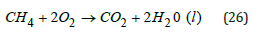
Table 7:The biogas components used in this study.

The thermal value of methane combustion is 34.83 Megajoule/ m3. The urban gas flow used in this research has been calculated to be 25 lit/min using a flow meter. Therefore, the input power to the system can be calculated through the total heat resulting from urban gas combustion. Urban gas flow meter device is shown in Figure 19.

Hydrogen sulfide combustion reaction equation will be as follows:
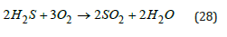
Figure 19:Urban gas flow meter device.

The thermal value of the combustion of Hydrogen sulfide is 36.503 Megajoule/m3. As this gas comprises about 0.2% of the biogas, it should be said that the input power resulting from the combustion of this gas can be described using the below equation:
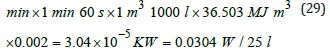
Therefore, it can be argued that, the input value resulting from the combustion of Hydrogen sulfide is very negligible compared with that of Methane. The reason behind it is that Hydrogen sulfide has a small share within the biogas. Therefore, the biogas could be considered against Methane with a good approximation.
The gas burner is responsible to maintain the temperature in the hot part of the engine while, water with a stabilized temperature is in charge of maintaining the temperature in the cold part of the motor (engine). Gas and water flow has been adjusted manually to bring about the necessary conditions for engine’s performance in its stable state. Since the variables are sufficiently stable in this state, using an automatic controller to adjust the gas and water flow may not be needed. Temperature sensors of thermocouple type have been used (as shown in Figure 20) to read the temperature of water in the inlet and outlet cooling parts of the motor as well as the temperature in two points of motor’s heating pipes.
Figure 20:Placement of temperature sensors on the base and tip of the motor heater [17].

Third stage: The conditions of testing the Stirling engine coupling for cold generation using a power supply and Helium gas
Figure 21 illustrates the schematic belonging to the coupling of Stirling engine. The left side is named hot engine which operates by receiving thermal energy from a heat source like biomass. In the right side, another Stirling engine can be seen which is named the cooling engine. This engine generates cold by receiving energy from the hot engine. This system includes two Stirling engines. The initial setup of the first engine requires a power supply and a generator which connect to the flywheel of the first engine. A few seconds after the setup, the generator can be disconnected so that the system can continue its operation. After launching the first engine, the second one will be started through the belt. According to the cycle of the Stirling engine, the rotation of the second engine will produce cold. The first Stirling engine, the hot one, and the second Stirling engine are named the cooling Stirling engine.
Figure 21:Schematic of Stirling engine coupling ST500 (hot and cold) to generate cold.

As for the engines to operate, it is needed that the two engines be coupled to one another. As illustrated in the figure below, a special insulation will be used in the heating part of the cooling engine so as to avoid cold energy wastes. Each of the two engines will be filled with Helium gas. In this part, care should be taken that the gas pressure of the hot engine be higher than that of the cooling engine so that the system will run more easily, because the average gas pressure of the hot and cold supplies is one of the most important factors of the experiment. One of the characteristics of Stirling engine is its requirement to be preheated before any use; therefore, in this study, urban gas will be used to heat the engine. A burner is used to preheat the engine for 5 minutes. The real representation of Stirling engine coupling ST500 (hot and cold) to generate cooling energy, heat burner of Stirling engine and hot engine’s temperature sensor and engine’s output reader device and Adams software are shown in Figure 22-24 respectively.
Figure 22:The real representation of Stirling engine coupling ST500 (hot and cold) to generate cooling energy.

Figure 23:Heat burner of Stirling engine and hot engine’s temperature sensor.

Figure 24:Engine’s output reader device and Adam (Adams) software.

Results and Discussion
Test results of the coupling of the two engines to produce cold
Table 8 demonstrates the initial conditions for 5 various tests done on the couple Striling engine to produce cold using Helium gas. In this experiment, the pressure of the Helium operating fluid is at best 8 bars in the heating source and the average pressure in the cooling source is 1 bar. Tests 1-5 have been carried out in a timespan of 2-4 minutes. For each of the five tests, the discharge water fluid from the copper coils has been considered as fixed. For a more precise comparison of the results, the input power from the power supply is considered stable. The ambient temperature in all five tests is 25 ºC. The temperature of the generated cold (T5) is measured by a temperature reader device.
Table 8:Different laboratory conditions for the couple Stirling engine to produce cold.

Figure 25 illustrates the temperature-time diagram of the 5 socalled experiments. As it is shown, when the pressure of the hot and cold sources changes, the temperature of the heating part rises and that of the cold part of the device decreases and consequently cold is produced. Eventually, by making use of a new experimental design which involves incorporating two Striling engines in varying temperature and pressure conditions as well as the presence of a biomass fuel, the average pressure of the heating/hot source increased by 8 bars and the cooling source temperature decreased by 1 bar; this in turn caused the temperature of the cooling part to (T5) reach to -16 ºC.
Figure 25:The temp-time diagram for the 5 carried-out tests with Helium gas in varying pressures and the couple state of Stirling engine to produce cold.

Test results of the coupling of the two engines to produce cold by the use of the Nlog code
as stated previously, the Nlog code is written using MATLAB software and it is used for the thermodynamic analysis of the Stirling engine. Nlog is an analysis code of Stirling engine’s cycle within which cubic equations are used. This code calculates the output heat and the power output of Stirling engine. By using this design, cold can be generated directly from the heat produced by renewable or non-renewable sources of energy. The obtained results for cold generation using Nlog have been compared with the results previously obtained and validated by other researchers [13]. The P-V diagram is shown in Figure 26.
Figure 26:P-V diagram.

As can be seen in the P-V diagram, according to the Nlog output, the black diagram represents the Schmidt mode, the blue one belongs to the cooler (the second Stirling engine), and the red one is for the heating (the first Stirling engine) and that they have a fine conformity. Using two Stirling engines in a coupled mode has a high efficiency in both thermal and electrical terms. Therefore, using the Stirling engine so as to produce cold can be a suitable option. For instance, it can be used to produce cold in both home and industrial sectors. Producing low levels of noise and vibration, and their capability of being built in small scales are among the advantages of Stirling engines in cooling mode.
Conclusion
In this study, two Stirling and coupling motors were investigated and a heat source was used for the high temperature source of the first Stirling engine. The output of the first Stirling engine moved the second Stirling engine to create a second cold Stirling engine. Optimization and production of cooling using biomass fuel in vitro using two Gamma type was performed for the first time in Iran Khodro Research and Development Center (Ipco Company) and the results of Stirling ST500 engine were analyzed. The results of this research can be used for the development of Stirling engines in the world and sustainable development, which have been important issues today, using the laboratory method and coupling of Stirling engines, as well as the use of renewable fuels. Finally, Stirling motors are used to apply cooling at pressures of different periodic temperatures. In this research, by using a new coupling structure of Gamma Stirling engine and by designing and constructing a heat chamber that works with biomass fuel, the mechanical power of the first Stirling engine can be increased.
Produced to cool at medium pressure, hot engine gas 8 times, average cold engine pressure 1 time and the final temperature of the first Stirling hot engine at 580 °C to cool in the second Stirling cold engine at -16 °C. With a careful design, select and increase the operating fluid pressure in the hot Stirling engine and reduce the average gas pressure in the cold source. The high heat output of the hot Stirling engine causes the temperature in the cold Stirling engine to decrease and it turns into a refrigerator. Heavier gases can also be used in Stirling engines, but these gases are less efficient than lighter gases such as helium and hydrogen. Smaller model engines also use air, but no other gas up to this level is used except in experimental cases.
Theoretically, the use of a light gas such as hydrogen or helium as the working fluid is recommended due to its low viscosity and high heat transfer coefficient. However, low molecular weight means an increase in the rate of fluid leakage from the engine, and as a result of the pressure drop, the efficiency of the increase in costs (fluid recharging) will decrease; High heat exchanger temperatures can cause parts to oxidize and corrode. In short, a gas can be selected as the optimal operating fluid, which in addition to being light, has a high heat transfer coefficient, low viscosity coefficient, low leakage potential and no oxidizing properties. In addition to the gases mentioned as working fluids, the researchers used gases such as carbon dioxide, water vapor and chemical composites.
References
- Kongtragool B, Wongwises S (2003) A review of solar-powered Stirling engines and low temperature differential Stirling engines. Renewable and Sustainable energy reviews 7(2): 131-154.
- Daneshgar S, Zahedi R, Farahani O (2022) Evaluation of the concentration of suspended particles in underground subway stations in Tehran and its comparison with ambient concentrations. Ann Environ Sci Toxicol 6(1): 019-025.
- Zahedi R, Golivari S (2022) Investigating threats to power plants using a carver matrix and providing solutions: A case study of Iran. International Journal of Sustainable Energy and Environmental Research 11(1): p. 23-36.
- Park J, Ko J, Kim H, Hong Y, Yeom H, Park S, et al. (2020) The design and testing of a kW-class free-piston Stirling engine for micro-combined heat and power applications. Applied Thermal Engineering 164: 114504.
- Cullen B, McGovern J (2011) Development of a theoretical decoupled Stirling cycle engine. Simulation Modelling Practice and Theory 19(4): 1227-1234.
- Altin M, Okur M, Ipci D, Halis S, Karabulut H (2018) Thermodynamic and dynamic analysis of an alpha type Stirling engine with Scotch Yoke mechanism. Energy 148: 855-865.
- Sauer J, Kuehl HD (2017) Numerical model for Stirling cycle machines including a differential simulation of the appendix gap. Applied Thermal Engineering 111: 819-833.
- Ipci D (2020) Thermodynamic-dynamic analysis of gamma type free-piston stirling engine charged with hydrogen gas as working fluid. International Journal of Green Energy 17(12): 805-815.
- Ferreira AC, Silva J, Teixeira S, Teixeira JC, Nebra SA (2020) Assessment of the stirling engine performance comparing two renewable energy sources: Solar energy and biomass. Renewable Energy 154: 581-597.
- Schmidt G (1871) The theory of Lehmann's calorimetric machine. Zeitschrift Des Vereines Deutscher Ingenieure 15(1): 98-112.
- Urieli I, Berchowitz DM (1984) Stirling cycle engine analysis. USA, p. 256.
- Finkelstein T (1994) Insights into the thermodynamics of Stirling cycle machines. In Intersociety Energy Conversion Engineering Conference.
- Prakash S, Guruvayurappan A (2011) Using stirling engine to increase the efficiency of an IC engine. In The World Congress on Engineering 2011, London, UK.
- Hagh MZB, Mahmoodi M (2012) Numerical solution of beta type stirling engine by thermal receiver application for increasing efficiency and output power. Journal of Basic and Applied Scientific Research 2(2): 1395-1406.
- Valenti G, Silva P, Fergnani N, Campanari S, Ravidà A, et al. (2015) Experimental and numerical study of a micro-cogeneration Stirling unit under diverse conditions of the working fluid. Applied Energy, 2015. 160: 920-929.
- Karami R, Sayyaadi H (2015) Optimal sizing of Stirling-CCHP systems for residential buildings at diverse climatic conditions. Applied Thermal Engineering 89: 377-393.
- Hooshang M, Moghadam RA, Nia SA, Masouleh MT (2015) Optimization of Stirling engine design parameters using neural networks. Renewable Energy 74: 855-866.
- Hooshang M, Moghadam RA, Alizadeh Nia S (2016) Dynamic response simulation and experiment for gamma-type Stirling engine. Renewable energy 86: 192-205.
- Amarloo A, Valian Ali K, Alireza B, Siamak A (2017) Thermodynamic analysis of performance parameter of a novel 3 cylinder Stirling engine configuration. Modares Mechanical Engineering 16(10): 448-458.
- Damirchi H, Najafi G, Alizadehnia S, Mamat R, Azwadi N, et al. (2016) Micro combined heat and power to provide heat and electrical power using biomass and Gamma-type Stirling engine. Applied Thermal Engineering 103: 1460-1469.
- Sheykhi M, Mehregan M (2018) Modeling of combined heating and power system driven by Stirling engine from the perspective of the fuel consumption and pollution emission. Modares Mechanical Engineering 17(10): 207-216.
- Kaldehi BJ, Keshavarz A, Safaei Pirooz AA, Batooei A, Ebrahimi M (2017) Designing a micro Stirling engine for cleaner production of combined cooling heating and power in residential sector of different climates. Journal of Cleaner Production 154: 502-516.
- Calise, F, Dentice d'Accadia M, Libertini L, Quiriti E, Vanoli R, et al. (2017) Optimal operating strategies of combined cooling, heating and power systems: A case study for an engine manufacturing facility. Energy Conversion and Management 149: 1066-1084.
- Erbay LB, Ozturk MM, Doğan B (2017) Overall performance of the duplex Stirling refrigerator. Energy Conversion and Management 133: 196-203.
- Ansarinasab H, Mehrpooya M (2018) Investigation of a combined molten carbonate fuel cell, gas turbine and stirling engine combined cooling heating and power (CCHP) process by exergy cost sensitivity analysis. Energy conversion and management 165: 291-303.
- Dai D, Yuan F, Long R, Liu ZC, Liu W (2018) Imperfect regeneration analysis of stirling engine caused by temperature differences in regenerator. Energy Conversion and Management 158: 60-69.
- Katooli MH, Moghadam RA, Hajinezhad A (2019) Simulation and experimental evaluation of Stirling refrigerator for converting electrical/mechanical energy to cold energy. Energy conversion and management 184: 83-90.
- Sowale A, Kolios AJ, Fidalgo B, Somorin T, Parker A, et al. (2018) Thermodynamic analysis of a gamma type Stirling engine in an energy recovery system. Energy conversion and management 165: 528-540.
- Masoumi A, Tavakolpour-Saleh A, Rahideh A (2020) Applying a genetic-fuzzy control scheme to an active free piston Stirling engine: Design and experiment. Applied Energy 268: 115045.
- Daneshgar S, Zahedi R (2022) Optimization of power and heat dual generation cycle of gas microturbines through economic, exergy and environmental analysis by bee algorithm. Energy Reports 8: 1388-1396.
- Zahedi R, Daneshgar S (2022) Exergy analysis and optimization of Rankine power and ejector refrigeration combined cycle. Energy 240: 122819.
- Bergman TL, Lavine AS, Incropera FP, DeWitt DP (2011) Fundamentals of heat and mass transfer (8th), John Wiley & Sons, Hoboken, New Jersey, USA, p. 992.
- Papanastasiou T, Georgiou G, Alexandrou AN (2021) Viscous fluid flow. CRC press, Boca Raton, Florida, USA
- Sista KM (1978) Continuous hydrogen reduction of copper from its sulfate solution: kinetic study in a plug flow reactor. The University of Oklahoma.
- Borgnakke C, Sonntag RE (2020) Fundamentals of thermodynamics. John Wiley & Sons, Hoboken, New Jersey, USA.
© 2022 Rahim Zahedi. This is an open access article distributed under the terms of the Creative Commons Attribution License , which permits unrestricted use, distribution, and build upon your work non-commercially.
Editor In Chief


.jpg)


Signup for Newsletter

Quick Links
 Editorial Board Registrations
 Submit your Article
 Refer a Friend
 Advertise With Us
Our Recent Edition

.jpg)


Top Editors


.jpg)


.bmp)
.jpg)
.png)
.jpg)


.jpg)


.png)

.png)


.png)


Financial Support

Sponsors

Latest e-Books

Latest Video

 a Creative Commons Attribution 4.0 International License. Based on a work at www.crimsonpublishers.com.
Best viewed in
a Creative Commons Attribution 4.0 International License. Based on a work at www.crimsonpublishers.com.
Best viewed in