
- About Us
- Information
-

The Author ensures that the research has been conducted responsibly and ethically with adherence to all relevant regulations. read more..
- For Authors
- For Reviewer
- Manuscript Guidelines
- Membership
- Publication Ethics
-
- Journals
- Reprints
- e-Books
- Videos
- Policies
- Contact Us
 COVID-19
- Submissions


Full Text
Evolutions in Mechanical Engineering
Simulation of Porosity Fractions in Aluminum Cast Structure for Aero Engine Applications
Govindarajan Narayanana*
Structures and Transmissions, Germany
*Corresponding author:Govindarajan Narayanana, Structures and Transmissions, Rolls Royce Deutschland Ltd & Co KG, Eschenweg, 11, Dahlewitz, 15827 Blankenfelde-Mahlow, Germany
Submission: October 10, 2021;Published: November 24, 2021

ISSN 2640-9690 Volume3 Issue5
Abstract
The simulation of casting process for bearing support structure and the material defect like porosity, distribution of porosity and volumetric porosity of the bearing structure is presented in this paper. The casting process has been iteratively simulated based on the predesigned casting parameters to forecast the real value of the porosity fractions. The finite element model of bearing support structure has also been simulated with GTN material model in order to compute the damage parameter over accumulated plastic strain with the predicted casting defects. The actual pore distributions on the bearing support structure are estimated from the real casting. The casting parameters are also be designed by iterative of casting simulations in order not to exceed the allowable casting defects. The simulated casting defects and casting parameters are also validated with real casting process. The simulated porosity fraction and actually obtained casting defects are well matched for the similar casting parameters.
Introduction
Casting method of manufacturing becomes so popular in many industries since their cost effective and abundant availability in spite of their limited fatigue life due to casting related material defects like porosity, dendrite arm spacing and formation of oxides. In particular to aero engine application, aluminium casting structure becomes more common compared to other casting alloys like magnesium cast and titanium cast alloys. Magnesium cast alloys prone to corrosion whilst the titanium cast alloys are susceptible for fire. Fatigue life estimation of cast aluminium alloys in aerospace application is very crucial since the casting defects can be treated as crack initiation sites and hence the propagation of pre-cracked condition contributes majorly into the total fatigue life. It is also more challenging to produce the casting without any defects otherwise cost is compromised. At many circumstances, the cast structures have to sustain with the internal defects of unknown sizes in such a level that the crack may not be propagated under designed loading condition. This leads to have a need for defining the accepting criteria for the internal casting defects which is quite challenging due to their randomness.
The acceptance criterion on porosity limit of the cast aluminium alloy has been set based on rational quality standards and previous experience on the particular structure. Recent increasing trend in specific fuel consumption and effective utilization of the static structures in aero engine application leads to have very optimum design at every corner. In order to relax the acceptance criterion on porosity limit on cast aluminium alloys either we need to generate proper fatigue data with reflection of cast defects or generating test data at component level experiments which will consume more cost and time. Since the fatigue properties and shrinkage porosity distribution in a cast aluminium alloy shows a very large scatterings and random nature, it is proposed to use stochastic modelling technique to address the current challenge. This way, the acceptance criteria as well as the fatigue life limit to the known casting defects is established. Prior to define the acceptance criteria on casting defects, it is evidently necessary to identify the casting parameters that influence the casting defects during the casting process. Prior to define the acceptance criteria of the casting defects, a projected level of porosity fraction for the given casting condition is needed to be established. For this a simulation of casting flow process is being planned by assuming the casting parameters. Further finite element analysis of casting structure with known Gurson- Tvergaard-Needlemans (GTN) material model with predicted porosity fraction under designed loading condition has also performed to get the accumulated plastic strains which control the fatigue life significantly. This paper is limited to only the simulation part of the casting of bearing support structure and compared to the real cast structures.
Simulation of the Casting Process
The cast aluminium alloy is prone to internal metallurgical defects, and it also impacts the quality of the casting. A casting flow simulation in order to predict the porosity distribution is planned under certain parameters which are: the flow of molten metal, solidification time, the fluid temperature of molten metal, and the alloying element. This casting flow simulation for the given mould has been performed by using FLOW-3D Cast analysis. It fundamentally uses the principle of volume of flow method. The simulation of the molten metal in the pre-modelled mould of the casting along with the defined volumetric flow, temperature of the molten metal and projected solidification time brings an indication not only about the volumetric porosity but also the distribution of pores at various features in the cast structures. For easiness, it is decided to use overall volumetric porosity fractions as a collection of the porosity which is randomly distributed in the bearing support structure in this paper.
Table 1: Material properties used for casting simulation.

This software has a principal of simulating fluid flow (molten metal) in the die with free surfaces in a defined discretized control volume of elements. The simulation region is reduced into the small representative volume of control elements in which the algebraic equations are established to describe the conservation of mass, momentum and energy shared with neighbouring elements. The motion of free fluid interfaces within the region of control elements and the measure of the air gap to molten metal is evaluated during the simulation. The parameters included in controlling the formed porosity during the casting process are explained in Table 1 and casting parameters iteratively changed in the simulation process. The outcome of this simulation is used to outline the casting parameters in order to achieve the defined porosity fractions from the prototype. The cast model is imported as geometry and treated as a mould cavity. The molten metal is then simulated for solidification process with tailored casting parameter to achieve the defined porosity fraction.
Figure 1:Flow chart for modelling for the current study.

The simulation of the casting process and structural analysis has been planned before executing the stochastic model for evaluating the fatigue life of cast structure. The simulation of the casting model provides better understanding on the manufacturing parameters in porosity defects. However, the structural analysis of the bearing support gives the working ranges of associated variables. The simulation models are discussed in this section based on the flow of modelling work described in the Figure 1. The stochastic modelling of fatigue life evaluation is out of scope in this paper. The solidification time caused by the shape and size of the castings, flow rate, cooling agents and alloying element composition bring out the variations in properties of the casting alloys. More iteration has been carried out in order to achieve converged porosity fraction which matches the current porosity fractions obtained in the real casting of bearing housing support structure. At the solidification time of 273 seconds, the micro porosity distribution across the bearing housing structure is simulated as shown in Figure 2. The Figure 2 contains porosity distribution at the beginning, middle and end of solidification time. The simulated porosity fractions, volumetric porosity and equivalent spherical diameter of the consolidated pores with respect to the solidification time are presented in the Figure 3.
Figure 2: Porosity distribution plot on the bearing housing structure (porosity volume) at initial, middle and final stage of solidification.

Figure 3: Simulated porosity parameters for various solidification times.

Finite Element Model of Cast Structure
The finite element model of bearing support structure has been prepared with more realistic boundary condition which includes parabolic pressure distribution of the maximum bearing load along with the porosity fractions obtained from the casting flow simulation for the realistic analysis purpose. The simulation of the casting process is mainly useful for controlling the manufacturing process whilst structural finite element analysis on the bearing structure gives the working range of the stress/strain under fatigue loads. The bearing loads are chosen in such a way that it represents the normal operating condition. These bearing loads are applied as parabolic pressure distribution in order to represent more realistic loading condition. In order to capture correct stiffness of both flanges, necessary adjacent structural elements are also considered in the analysis. A bilinear isotropic material model is considered besides GTN material model. The damage at initial condition is applied in this model as a uniform distribution since there is no direct link available from Flow 3D to ANSYS. The boundary condition, load application, meshing quality and material model parameters of the bearing structure and normalized strain under the normal operating condition are shown in the Figure 4.
Figure 4: Finite element model of the cast bearing support structure with porosity definition by GTN material model.

Since the damage is the loss of material integrity of a material, micromechanically it is introduced as a destruction of atomic bonds and growth of micro cracks and pores. The damage could be either brittle or ductile nature based on the specific materials. A scalar internal damage variable ‘D’ is introduced to consider relative load carrying cross section and to describe the isotropic damage. The force acting on the specimen is effectively carried away by only nondamaged area. The effective stress seff would then be defined in the following equations.
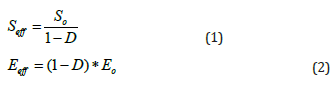
So and Eo is the stress of homogeneous or undamaged material and Young’s modulus respectively.
The cast structures with internal material defects subjected to heavy loading are prone to volume or density change over fatigue or prolonged load cycles. The internal defects like porosity can grow due to ductile damage process though the aluminum cast structure is considered to be brittle or low ductile. It is also expected in the case of any geo-materials and powder metallurgy [1], where internal defects may nucleate at neighboring defects and grows by plastic deformation experienced at near defect edges. It finally provides meso-crack size by coalescence. Gurson proposed a damage mechanics which is based on vonMises criteria [2]. This material model mathematically describes mainly two mechanisms (void nucleation and void growth); however Gurson-Tvergaard- Needleman (GTN) model describes the all the three mechanisms [3].
The GTN material model may be used in numerical structure simulations to predict flow localization or final failure. The basic assumption in GTN model contains a hollow equivalent sphere which is representative of all the material defects. The damage variable is related to the volume fraction (Pf) of the porosities. It is considered to be elastic-plastic with isotropic material hardening (R) and yield strength (SY) as Ss = SY + R. The evolution equation of porosity has been modified by Needleman et al. [4] by assuming isotropic damage. Plastic potential is written with effective vonMises equivalent stress Seq, Isotropic hardening stress, R, and the yield stress SY in below equations.
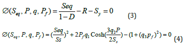
D is defined as an isotropic damage scalar and can be considered similitude to porosity fraction. q1, q2, and q3 are representing the Tvergaard-Needleman constants. The hydrostatic pressure state of stress is defined as ‘P’. 𝑃𝑓 is void’s volume fraction as internal variable and the ratio, P/Ss is none other than defined as triaxiality ratio.
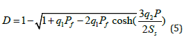
By solving for damage variable from the equations 1 in to 4, the damage is computed as below equation.
The Tvergaard-Needleman function is used to model the loss of material load carrying capacity, which is associated with void coalescence. When the current porosity f* reaches a critical value, load carrying capacity of the material decreases more rapidly due to void coalescence. When the porosity f reaches a higher value fc, the material load carrying capacity is lost completely. The associative plasticity model for the GTN model has been implemented. There are two parts which contribute to the increase of the void volume fraction, one is the growth of the existing voids and the other is the nucleation of new voids during the loading. The simulated stress strain curve for various porosity fractions is plotted in Figure 5 along with the similar material data found in Zeng et al. [5]. The bearing housing structure is modelled with Gurson material parameters by using ANSYS WORKBENCH general FE software. The cast aluminium alloy doesn’t depict much isotropic hardening effect under loading condition for higher porosity fractions. When the initial porosity fractions in the cast structure are increasing, it will lead to more occurring damage under the fatigue loading as shown in Figure 6. All the above results correspond to the damage that produces equivalent stress which is defined in overall equivalent porosity fractions obtained from the previous fluidstructure interaction simulations based on conservation of strain energy function [6].
Figure 5: Stress-Strain diagrams simulated for various casting and porosity fractions. (Values are not shown due to conflict of proprietary data).

Figure 6: Damage parameter over the strain for two different initial porosity fractions.

The above finite element calculations are performed on the bearing support structure in order to get the working ranges of stress and fatigue life of the component. Since it is quite challenging in controlling the porosity fractions in the bearing support structure, it is planned to use the cut-up specimens from the cast bearing support structure with similar representative porosity fractions. The simulation of the damage computation on bearing support structure provides material damage at macroscopic level at working load ranges. Based on the structural analysis, the acceptable limit of volumetric porosity fractions is derived out by comparing the results obtained from prototypes of casting samples as shown in the Figure 7.
Figure 7: Simulated porosity parameters for various solidification times along with the real cast scenarios.

Conclusion and Observation
The casting simulation of the structure provides the dependency factors for controlling the porosity fraction whilst the structural finite element analysis along with the GTN material modelling which represents the porosity provides estimation on the life integrity. The outcome results of combining the porosity simulation of casting flow analysis provide the input to the structural analysis which calculated the damage occurred in the bearing support structure. The limitation on the acceptable level of porosity fraction (at volume level) for the bearing support structure is derived out by comparing the simulation results with the real prototype in order to validate the parameters that are set for the manufacturing process of support structure. Figure 7 is established in order to compare the simulation results with the outcome of the prototypes which are closely matching in spite of some discrepancy which is adjudicated to be the gap between the real cast to simulation along with the boundary condition effect.
References
- Narayanan G, Gnanamoorthy R (2007) Study of damage mechanisms and failure analysis of sintered and hardened steels under rolling-sliding contact conditions. Materials Science and Engineering 445-446: 259-268.
- Gurson AL (1977) Continuum theory of ductile rupture by void nucleation and growth: Part I-Yield criteria and flow rules for porous ductile media. Journal of Engineering Materials and Technology 99(1): 2-15.
- Thomas MF, Pradeep M, Dhafer M, Cing DK (2008) A study of the Gurson damage model and numerical simulation of ductile failure in LS Dyna, LS Dyna Anwenderforum. Bamberg, Germany.
- Needleman A, Tvergaard V (1984) Analysis of ductile rupture in notched bars. Journal of Mechanical Physics Solids 32(6): 461-490.
- Zeng L, Sakamoto J, Fujii A, Noguchi H (2014) Role of eutectic silicon particles in fatigue crack initiation and propagation and fatigue strength characteristics of cast aluminium alloy A356. Engineering Fracture Mechanics 115: 1-12.
- Madhusudhan, Narendranaath S, Mohankumar GC, Mukunda P (2010) Effect of mould wall thickness on rate of solidification of centrifugal casting. International Journal of Engineering Science and Technology 2(11): 6092-6096.
© 2021 Govindarajan Narayanana. This is an open access article distributed under the terms of the Creative Commons Attribution License , which permits unrestricted use, distribution, and build upon your work non-commercially.
Editor In Chief


.jpg)


Signup for Newsletter

Quick Links
 Editorial Board Registrations
 Submit your Article
 Refer a Friend
 Advertise With Us
Our Recent Edition

.jpg)


Top Editors


.jpg)


.bmp)
.jpg)
.png)
.jpg)


.jpg)


.png)

.png)


.png)


Financial Support

Sponsors

Latest e-Books

Latest Video

 a Creative Commons Attribution 4.0 International License. Based on a work at www.crimsonpublishers.com.
Best viewed in
a Creative Commons Attribution 4.0 International License. Based on a work at www.crimsonpublishers.com.
Best viewed in