
- About Us
- Information
-

The Author ensures that the research has been conducted responsibly and ethically with adherence to all relevant regulations. read more..
- For Authors
- For Reviewer
- Manuscript Guidelines
- Membership
- Publication Ethics
-
- Journals
- Reprints
- e-Books
- Videos
- Policies
- Contact Us
 COVID-19
- Submissions


Full Text
Evolutions in Mechanical Engineering
Thermal Analysis of a Workpiece Material in an Electric Discharge Process
Debabrata Datta*
Information Technology, Heritage Institute of Technology, India
*Corresponding author:Debabrata Datta Professor, Information Technology, Heritage Institute of Technology, Kolkata - 700107, India
Submission: May 12, 2021;Published: September 03, 2021

ISSN 2640-9690 Volume3 Issue4
Abstract
EDM is a non-conventional thermo electric process wherein material erodes from the workpiece by a series of discrete sparks between the tool and workpiece immersed in a dielectric medium. This discharge occurs in a voltage gap between the electrode and workpiece. Thermal analysis is essential to quantify the material removal rate and also to know the performance of the material with respect to the defined process. A substantial research has been carried out to qualify the material under process. However, due to complex processes involved an advanced analysis is mandatory. Present study explains how one can understand the behavior of a workpiece for participating in EDM process. Thermal analysis model accurately predicts the temperature profile, material removal rate and quality of the product. The basic objective of this paper is to explore the thermal analysis of the material in terms of a workpiece in EDM.
Keywords: EDM; Thermal analysis; Sparks; Electrode
Abbreviations: EDM: Electric Discharge Machine; MRR: Material Removal Rate
Introduction
Electric Discharge Machine (EDM) is now become the most important established
technique in modern industries since many complex 3D shapes can be machined using a
simple shaped tool electrode. EDM is a non-conventional, thermo electrical process, which
erodes material from the workpiece by a series of discrete sparks between the tool and
workpiece immersed in a dielectric medium. This discharge occurs in a voltage gap between
the electrode and workpiece. Heat from the discharge vaporizes minute particles of workpiece
material, which are then washed from the gap by the continuously flushing dielectric fluid.
The benefits of EDM include:
1. EDM is a non- contact process that generates no cutting forces, permitting production of
small and fragile pieces.
2. Burr-free edges are produced.
3. Intricate details and superior finishes are possible and
4. EDM machines with built-in process knowledge allow the production of intricate parts
with minimum operator intervention.
The limitations of EDM include:
a. low metal removal rates compared to chip machining and
b. lead time is needed to produce specific, consumable electrode shapes.
As material removal is realized without physical contact between the tool and work piece,
there is no force exerted on the work piece, adding to the advantages of the EDM in fabricating
intricate micro scale features. Efforts in modeling the EDM process has given an insight for
modeling the Micro EDM process where it differs from the conventional EDM process in the
amount of material removal and the accuracy of the process [1]. The material removal process in EDM is very stochastic in nature. The dielectric between the
electrodes breaks down and a spark channel also known as plasma
channel is formed. The fabrication of an electrode with diameter
2.8μm and micro-hole as small as 5μm as well as 42μm micro-slit
with a length 7mm has been reported. During the discharge, the
region within the whole spark is in the plasma state.
The plasma consists of atoms dissociated into positive ions and
electrons and is highly conducting. The complete plasma region can
be considered an equipotential region at some specific potential.
The plasma potential is actually controlled by the positive electrode
potential and differs slightly from it. Therefore, with respect to
the plasma potential, the cathode is at a negative potential, and
the plasma potential is considered as reference potential i.e., at
zero potential. A strong electric field appears at the cathode due
to this large potential drop in this sheath near the electrode. The
models incorporate voltage, current, pulse on time to predict the
temperature distribution on the workpiece. It is assumed that the
entire superheated area is ejected from the workpiece surface and a
small fraction of the molten area is ejected. This helps in predicting
the size and shape of the crater. Experimental works directed in
material removal characteristics using single RC pulse discharges
give an insight about the process [2]. The works directed in the
study of pulse generators for Micro EDM gives an insight to the
process [3].
Cylindrical plasma with variable mass model is developed for
sparks created by electrical discharge in liquid media [4]. Finite
element method has been used for the development of twodimensional
axis symmetric model for powder mixed dielectric [5].
The developed model predicts first the temperature distribution
in the workpiece electrode using ANSYS software and the Material
Removal Rate (MRR) is estimated from the temperature profiles
[6]. Theoretical finding are found is good agreement with the
experimental results. In the field of EDM, most of the published
work is focused on the models based on transistor pulse generator.
Different aspects of machining have been considered like pulse-ontime,
pulse-off time, spark gap, etc. Further the single discharge
for energy input to the workpiece is taken into consideration for
predicting the temperature distribution of the workpiece. The crater
size of the work piece is determined by accounting the fraction of
energy used as well as fraction of the molten area expelled from the
material. Quantification of the fraction of the energy received by the
workpiece is based on the Saha Ionization formula.
Electro Thermal Model
In EDM on the basis of experimental evidence, electro thermal theory representing EDM process suggests that material removal in EDM operations takes place as a result of the generation of extremely high temperature generated by the high intensity of the discharge current [7]. In order to start the derivation of the temperature distribution of the workpiece on the basis of the electro thermal model, it is always better to have a summary of the mechanism of the parent process. Following section presents a short summary of process mechanism.
Process mechanism
A two dimensional heat transfer for a material subjected to a disc heat source on its surface is used as the foundation for the present model. The plasma channel radius (heat flux radius) of the anode and cathode is based on empirical formulation. The generation of a single discharge is shown in Figure 1. Tool and work piece are separated by a dielectric medium and contacted with a voltage. Whenever the electric field is stronger than the dielectric strength it comes to discharge. The materials of the tool and work piece around the plasma channel are strongly heated and molten or vaporized. After the discharge time the plasma channel implodes. The eroded material is flushed out by this implosion.
Figure 1:Phenomenological model of a single discharge.

Mass of electrons is higher compared to the mass of ions and accordingly movement of ions is slower compared with electrons. Hence the electrons will reach the anode first followed by the cathode with one or two orders of magnitude delay in time. Consequently, the anode will melt first resulting in a larger molten area as compared with the cathode, which in general case in micro- EDM where pulse on time is short [8]. As time progresses, anode begin to solidifies further after a few microseconds due to the decrease in the local heat flux at the anode surface, while the molten area in the cathode still expands. Hence the molten areas in anode will be smaller as compared with the cathode, which are prevalent in the conventional EDM.
Heat transfer model of EDM
Heat transfer model that executes in EDM is based on certain
assumptions such as (a) the workpiece domain is considered to
be axisymmetric, (b) the composition of workpiece material is
quasi-homogeneous, (c) the heat transfer to the workpiece is by
conduction, (d) only one spark occurs for one discharge of energy
input, (e) average thermo physical properties are applied over the
temperature range, from solid to liquid state, (f) radiation and
convection heat losses are negligible, (g) the initial temperature was
set to room temperature in single discharge analysis, (h) the energy
used for the material removal is only contributed by the voltage
and current during pulse on time, (i) the fraction of discharge
energy going to the anode and cathode is taken as a constant,
(j) the material in the superheated area is removed completely
while only a constant fraction of the material in the molten area is
removed, (k) the workpiece is assumed as stress-free before EDM,
(l) the thermal properties of workpiece material are considered as
a function of temperature, (m) it is assumed that due to thermal
expansion, density and element shape are not affected and (n) the
heat source is assumed to have Gaussian distribution of heat flux on
the surface of the workpiece.
The governing Partial Differential Equation (PDE) representing
the heat transfer process in EDM problem without heat generation
is given by

where α is the thermal diffusivity of the material (m2s−1) and
can be written as, 
Kt represents the average thermal conductivity (Wm−1 0K−1), ρ signifies the density (kg/m3) and Cp presents the specific heat (J/kg/0K) of the material of the workpiece to be considered for temperature distribution. Plasma channel incident on the workpiece surface causes the temperature to rise in the workpiece. The distribution of plasma channel can be assumed as uniform disc source or Gaussian heat distribution. Figure 2 represents the axisymmetric diagram of thermal model.
Figure 2:Axisymmetric thermal model of EDM.

The representative initial and boundary conditions are as follows:
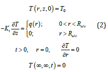
where, q(r) is the heat flux due to the spark and Ra/c is the heat flux or spark radius and T0 represents the initial (ambient or room) temperature (0K) of the workpiece. Heat flux applied to workpiece in EDM is considered as a Gaussian distribution. Literature study evidenced that the assumption of Gaussian distribution is authentic to model the heat input in EDM [9,10]. Further, as the tool and the workpiece have been assumed to be thermally isotropic, therefore, the heat distribution would be Gaussian in nature on the surface of both workpiece and tool. In view of all these evidences and facts, Gaussian heat distribution is considered in the present work. The heat flux can be written as
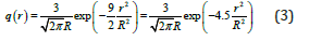
Where the symbols have usual significance. Now, at r = 0, q(R) = q(0) = peaked value = qmax (say).
Therefore, we have now, 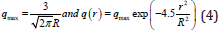
A little bit of algebraic manipulation results the heat flux at the surface of the workpiece is written as
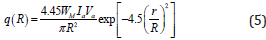
Where WM is the fraction of energy utilized by the material (Watt), Ia is the anode pulse current (Amp), Va is the voltage (Volt) applied to anode, Rc/a is the heat flux radius (plasma channel radius) of the cathode or anode (μm) and r is the radial distance from the axis of the spark (μm). The radius of heat flux radius is empirically formulated by least square fitting of experimental results for a typical discharge energy range 5-100μJ with a coefficient of determination value of 0.9651 and the same is given by
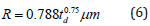
where R is the heat flux radius at anode and td is the pulseon- time in microseconds. The distribution of temperature as a theoretical model is written as
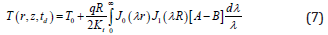
Where,
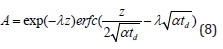
and
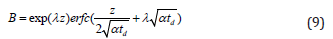
where J0(λ r) and J1(λ R) are Bessel functions of the first kind of zero and first order, respectively, and erfc(η ) is the complementary error function. The dimensionless form of temperature profile along the vertical axis (r = 0) of the workpiece under investigation in EDM is
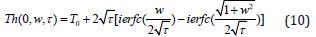
where ierfc( Ω ) represents the integral error function. We can further simplify Eq. (10) by retaining its dimension form as
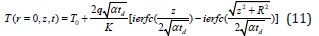
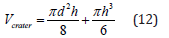
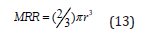
Assuming h as the depth of the molten material and d as the radius of the hemisphere of the crater, the performance of any electro thermal model of EDM process is qualified in terms of material removal rate, surface roughness and accordingly the volume of the crater formed during melting can be formulated by fundamental geometry as
The material removal volume in a single spark can be alternately expressed as
Results and Discussion
In order to simulate a predictive model of the temperature distribution in the material, the workpiece is taken as Copper and AISI 304 Stainless Steel (SS). Thermal properties of Copper and AISI 304 Stainless Steel are used as input to compute the temperature distribution of workpiece are shown in Table 1. The dielectric medium used to remove the debris is considered as kerosene in this study. The machining parameters, i.e., magnitude of the average gap voltage, Va, and the average current, Ia during pulse-on-time used as input in the computation of temperature profile of the present electro-thermal model are tabulated in Table 2.
Table 1: Thermal properties of the work piece material.

Table 2: Machining parameters for Cu and AISI SS workpiece.

Discharge times used in the computation have varied from 10 to 50 microseconds with a step increment of 10 micros seconds. Variation of spark radius or plasma channel radius with discharge time is shown in Figure 3. Temperature distribution on the top surface from the centre of the workpiece of material copper for operating voltage of 100 volt and current of 30 amp for various discharge times along the radial direction is shown in Figure 4 and the same from the centre (r = 0, z= 0) along the vertical direction (increase of the depth of the workpiece) is shown in Figure 5. Temperature distribution on the top surface from the centre of the workpiece of material AISI SS 304 for operating voltage of 50 volt and current of 10amp for various discharge times along the radial direction is shown in Figure 6 and the same from the centre (r = 0, z = 0) along the vertical direction (increase of the depth of the workpiece) is shown in Figure 7. Therefore, it is understood that machining parameters of EDM depend on the material to be considered as job.
Figure 3:Variation of plasma channel radius with discharge time.

Figure 4:Temperature profile on surface of Cu workpiece along the radial direction.

Figure 5:Temperature profile on surface of AISI SS 304 workpiece along the radial direction.

Figure 6:Temperature profile of the workpiece (Cu) along the vertical direction.

Figure 7:Temperature profile of the workpiece (AISI SS 304) along the vertical direction.

It can be envisaged from Figure 6 that if the workpiece material is made of copper and if we operate machine at an average voltage of 100 volt and at an average current of 30 ampere, maximum temperature along the axial direction of the workpiece occurs at a depth of 100mm for a discharge time of 20ms. However, occurrence of maximum temperature at a certain depth of the workpiece is completely dependent on machine parameters and from this angle, maximum temperature of the Cu workpiece at a certain depth of 100mm for various discharge time at different operating voltage and a fixed current of 30 ampere is shown in Table 3a and that of the AISI SS 304 at the same depth (100mm) for various discharge time at different operating voltage and a fixed current of 10 amp is shown in Table 3b. The code written by author can produce the same for conditions of varying current at a fixed operating voltage for different workpiece material. Experiments have been performed for allowing a discharge time as shown in Table 3a and Table 3b with respect to an average volt of 100, 110 and 120 for an average current of 30 amp and 10 amp respectively. Experimental values found within +/- 98% of theoretical values.
Table 3a: Maximum temperature along the axial direction of w Workpiece (Cu) at an average current of 30 amp for various discharge time and various operating voltage.

Values shown within () in columns 2-6 of Table 3a represent experimental values.
Table 3b: Maximum Temperature along the axial direction of workpiece (AISI SS 304) at an average current of 10 amp for various discharge time and various operating voltage.

Values shown within () in columns 2-6 of Table 3b represent experimental values.
Table 3a & 3b proves that model validation with experimental values. Table 4a shows the maximum temperature profile of the workpiece Cu for various discharge time when machine operating voltage is fixed at 100 volts with various operating current. Table 4b shows the maximum temperature profile of the workpiece AISI SS 304 for various discharge time when machine operating voltage is fixed at 50 volt with various operating current. A 3D plot of the temperature distribution profile of the workpiece (Copper) for an operating voltage of 100 volt and the optimum operating current of 15 amp for a discharge time of 20ms is shown in Figure 8a & 8b. No experiments have performed for maximum axial temperature of Cu workpiece and hence no experimental values are shown in Table 4a & 4b. A 3D plot of the temperature distribution profile of the workpiece (AISI SS 304) for an operating voltage of 50 volt and the optimum operating current of 15 amp for a discharge time of 20ms is shown in Figure 8a & 8b. It is obvious from Table 3 & 4 that machining parameters for removing different material being different, an optimization for the best performance of the system as EDM is essential. It is also evident from Table 4a that at any fixed operating voltage for a fixed discharge time, maximum temperature of the Cu workpiece at a fixed depth increases with the increase of operating average current first and then decreases with the increase of operating average current. Therefore, it can be concluded from Table 4a that for every discharge time (10-50ms), maximum temperature of Cu workpiece optimizes at operating current of 15 ampere when machine operates at an average voltage of 100 volt. On the other hand, the similar behavior is not valid for AISI SS 304 workpiece (Table 4b).
Table 4a: Maximum Temperature along the axial direction of workpiece (Cu) for operating voltage of 100 volt at various operating current with various discharge time.

Table 4b: Maximum Temperature along the axial direction of workpiece (AISI SS 304) for operating voltage of 50 volt at various operating current with various discharge time.

Figure 8a: 3D Temperature profile of Cu workpiece at 100V and 15A for discharge time of 20s.

Figure 8b: A side view of 3D Temperature profile of Cu workpiece at 100V and 15A for discharge time of 20s.

But Table 4b shows that optimization of maximum temperature of AISI SS 304 workpiece is occurred for a discharge time of 20ms for an operating average current of 15 amp provided that machine operates on an average voltage of 50 volt. Therefore, if the machine is operated on 100 volt then optimum operating current should be 15 ampere to get the maximum temperature at any axial point that is at a fixed depth of the workpiece Cu under study whereas the optimization of maximum temperature of AISI SS workpiece takes place at any discharge time of 20ms for operating condition of machine at 50 volt and 15 amp. So, optimization of the machine parameters can be fixed from this kind of study. Material removal rate can be simply defined as the amount of material removed per unit time. In this paper we have addressed the material removal rate, which is the quantification of the material removed for a certain period of time. MRR depends on the temperature of the workpiece beyond its melting point. The melting point of the workpiece under study is 1356 oK. It can be easily said from Figure 6 that, if machine is operated at a voltage of 100 volt with an operating current of 30 ampere, the temperature occurred at a depth of 55mm for a discharge time of 20ms goes beyond the melting temperature and accordingly 55mm can be taken as the depth of the workpiece at which melting starts. It can be mentioned from Figure 4 that at this discharge time the radius of the plasma channel becomes 2.4mm. The volume of the material cut is obtained as 8.72x10⁴((mm)3 and subsequently the material removed in weight is quantified as 0.7534mg. In a similar way, the amount of AISI SS 304 material removed is obtained as 0.01mg. Performance is assessed in terms of maximum amount of MRR for a very short time (Figure 9a & 9b).
Figure 9a: 3D Temperature profile of AISI SS 304 workpiece at 50V and 15A for discharge time of 20s.

Figure 9b: A side view of 3D temperature profile of AISI SS 304 workpiece at 50V and 15A for discharge time of 20s.

Conclusion
The theoretical model for the micro-EDM process has been developed based on the electro-thermal output. The present model computes the temperature distribution along the vertical and radial axes of the workpiece (job). The input parameters to approximate the dimensional geometry of the removed material are taken from the simulated results. Monte Carlo simulation has been applied for numerical computation of the integral appeared in the analytical formula of the temperature distribution (Eq. (6) and (10)). Future work is planned for validating the theoretical results of the temperature profile and crater depth, with the corresponding experimental result. In summary, the present model can simply offers quick information for performing experiment with EDM by simple adjustment of the parameters.
References
- Dibitotnto DD, Ebunk PT, Patel MR, Barrufet MA (1989) Theoretical models of the electrical discharge machining process. I. A simple cathode erosion model. Journal of Applied Physics 66(9): 4095-4103.
- Carslaw HS, Jaeger JC (1986) Conduction of heat in solids. (2nd edn), Oxford University Press, UK.
- Dhanik S, Joshi SS (2005) Modeling of a single resistance capacitance pulse discharge in micro-electro discharge machining. Int J Manuf Sci Eng Trans. ASME 127(4): 759-767.
- Ebunk PT, Patel MR, Barrufet MA, Bozkurt B (1993) Theoretical models of the electric discharge machining process. III. The variable mass, cylindrical plasma model. Journal of Applied Physics 73: 7900-7909.
- Han F, Chen L, Yu D, Zhou X (2007) Basic study on pulse generator of micro-EDM. International Journal of Advanced Manufacturing Technology 33: 474-479.
- Jilani ST, Pandey PC (1982) Analysis and modeling of EDM parameters. Precision Engineering 4(4): 215-221.
- Kansal HK, Singh S, Kumar P (2007) Numerical simulation of powder mixed electric discharge machining using finite element method. Journal of Mathematical and Computer Modeling 47(11): 11-12.
- Kurnia W, Tan PC, Yeo SH, Tan QP (2009) Surface roughness model for micro electrical discharge machining. Journal of Engineering Manufacture 223: 279-287.
- Tan PC, Yeo SH (2008) Modeling of overlapping craters in micro-electrical discharge machining. Journal of Applied Physics 41: 1-12.
- Xia H, Kunieda M, Nishiwaki N (1996) Removal amount difference between anode and cathode in EDM process. IJEM I 45-52.
© 2021 Debabrata Datta. This is an open access article distributed under the terms of the Creative Commons Attribution License , which permits unrestricted use, distribution, and build upon your work non-commercially.
Editor In Chief


.jpg)


Signup for Newsletter

Quick Links
 Editorial Board Registrations
 Submit your Article
 Refer a Friend
 Advertise With Us
Our Recent Edition

.jpg)


Top Editors


.jpg)


.bmp)
.jpg)
.png)
.jpg)


.jpg)


.png)

.png)


.png)


Financial Support

Sponsors

Latest e-Books

Latest Video

 a Creative Commons Attribution 4.0 International License. Based on a work at www.crimsonpublishers.com.
Best viewed in
a Creative Commons Attribution 4.0 International License. Based on a work at www.crimsonpublishers.com.
Best viewed in