
- About Us
- Information
-

The Author ensures that the research has been conducted responsibly and ethically with adherence to all relevant regulations. read more..
- For Authors
- For Reviewer
- Manuscript Guidelines
- Membership
- Publication Ethics
-
- Journals
- Reprints
- e-Books
- Videos
- Policies
- Contact Us
 COVID-19
- Submissions


Full Text
Evolutions in Mechanical Engineering
Vacuum Treatment of Metal in the Process of Continuous Casting
Protasov AV*
Researcher (Academic)-Institute of Metal Physics, Ural Branch of the Russian Academy of Sciences, Russia
*Corresponding author:Protasov AV, Researcher (Academic)-Institute of Metal Physics, Ural Branch of the Russian Academy of Sciences, Russia
Submission: November 18, 2019;Published: April 9, 2021

ISSN 2640-9690 Volume3 Issue3
Mini Review
One of the promising areas of liquid steel processing is the development of metal vacuum treatment in the stream during continuous casting (flow vacuum treatment). Several technological schemes of such processes have been developed, however, in practice, the only variant of the process has been implemented at the conditions of converter shop No-2 of Novo-Lipetzk Metallurgical Combine (NLMC) (Figure 1). The technology of flow vacuuming is based on the theoretical works of Professor G A Sokolov [1]. A steel ladle with a special jointing element covering the slide valve is installed on the supports of the CCM, then the hydraulic cylinder is attached to slide valve and the compressed air is given to assembling device.Then the slide valve is opened and vacuum chamber with the help of hydrocylinders is lifted to connecting with the ladle, while the metal fills the bottom of the vacuum chamber and flows through the pouring pipe into the intermediate tundish, stopper of the tundish is raised to ensure a minimum distance between the end of the (submersible pouring pipe) and the tundish bottom. The technological process is based on the vacuum degassing of the jet and the metal layer in the vacuum chamber located between the steel ladle and the tundish of Continuous Casting Machine (CCM). Refined steel enters the intermediate bucket on a tube submerged to the level of metal. During vacuum treatment, the difference in metal levels in the tundish and in the chamber is balanced by external pressure and forms barometric height.
Figure 1:The principal scheme of flow vacuumator in NLMC: 1-Vacuum camera; 2-Neck; 3-Dipped tube; 4- Hydro cylinder; 5- Flange of the steel ladle; 6-CCM intermediate ladle (tundish); 7-A stream of vacuum-filled metal; 8-A layer of metal; 9-Crystallizer; 10-Pourig glass; 11-Layer of synthetic slag.

After raising the level of metal in the tundish up to about 100mm above the end of the pouring pipe with the formation of a hydraulic shutter in 18-24 seconds pressure in the vacuum chamber is reduced to 0.67kPa. As the tundish is filled, the casting and vacuum treatment of the metal occur in a stationary mode until the moment, when in each strand about slab left to cast. Then the vacuum pump is disconnected , the system is filled with argon to atmospheric pressure the steel ladle is disconnected bucket and close the vacuum seal is covered. When a slag appears in the hole of the steel ladle is closed by slide valve and the ladle is removed from the stand. The results of operation give highly efficient vacuum degassing due to favorable kinetic conditions for degassing and carbon deoxydation. When the jet enters the rarefied space in its volume there is many gas germs are appeared, which turn the jet of metal into a foam-like bubble-film structure with a developed and constantly updated interphase surface. The vacuum also works well on thin layer of metal on the bottom of the vacuum chamber. The vacuum treatment of steel in the stream occurs at a velocity rate equal to the velocity of continuous casting, which ensures that the work of CCM and vacuum treatment coordinated and eliminates the need for additional time for vacuum metal processing. Thermal losses in vacuum treatment are 5-10 °C, which, taking into account the higher fluidity of vacuum treated steel, have little impact on the temperature regime of the smelting. By that reliable protection of liquid metal from secondary oxidation is ensured. In the process of vacuum treatment in the stream of aluminium-killed calm steels there is a noticeable decrease of oxygen in the metal (on average by 50%).
The application of this technical solution in the conditions of the oxygen-converter shop No-2 of the Novolipetsky Metallurgical Combine allowed to significantly improve the quality of the metal and master the production of new complicated brands of steel. Taking into account the results, the domestic priority in this area of out-of-the-surface steel processing, wide spreading of continuous casting in recent years and the need to effectively protect the poured metal jet, development of flow stream degassing and creating of industrial units are actual tasks that require improvements in design and technology based on science-based recommendations. The described flow vacuum unit, in fact, is a pilot unit with a number of technological, constructive and organizational problems, in particular: There is absence of possibility of entire continuous vacuum treatment of a series of continuously casted melts:
a. A significant amount of non-vacuumed metal at the
beginning and end of the casting;
b. The risk of creating emergencies when the residual
pressure in the vacuum chamber is drastically reduced or
increased;
c. The unstable operation of the continuous casting machine
in consequence of significant fluctuations in the level of metal
in the crystallizer and the lack of permanent protection of the
jet of metal poured into the crystallizer;
d. Low reliability of vacuum seals in the connection of a ladle
with a vacuum chamber located near the jet of poured metal;
e. The need for a park of special ladles with connecting
devices.
Thus, there is an objective need to create a new generation of industrial vacuumators without of these shortcomings. Taking into account the experience of operating the flow vacuumator at NLMK by specialists of TCNIIChermet, Vniimetmash, work Yumz and the metallurgical combine «Saporizhstal» (Ukraine) developed a new version of flow vacuumator, distinguished by the presence of an additional tundish with capacity 5-15% of the capacity of the steel ladle, vacuum-tightly mounted on the vacuum-camera, and vacuum tight slide walve placed between the addition tundish and the vacuum chamber (Figure 2) [2,3]. After installing a steel ladle, vacuum-camera with an additional tundish and an tundish of CCM in their original position, ladle is lowered, its slide valve is opened, after filling the metal of the additional tundish to a height of 200- 300mm the slide valve, located between the additional tundish and vacuum-camera is opened and metal through the poured pipe of vacuum-camera fill the tundish of CCM. After the flooding of the vacuum-camera poured tube on the 100mm (creation of the hydro shutter) vacuum shutter is opened and vacuum is created in the vacuum-camera at the same time as the metal fill the additional tundish, the vacuum-camera, and tundish of CCM. After filling the tundish to 500mm, it is lowered together with a vacuum chamber and a drive to a predetermined amount of immersion of the protective tube in the crystallizer and he stoppers are opened. When the metal is further fills tundish , the vacuum chamber is lifted, keeping the pipe deep into the metal within the range until the nominal level of the metal attained. The replacement of ladle by serial casting is made at the minimum level of metal in the additional tundish, equa l300mm. Compared to similar equipment, this flow vacuumator has the following advantages:
Figure 2: Scheme of advanced stream vacuum treatment process: 1-Steel ladle; 2-Additional tundish; 3-Vacuum-camera; 4-Tundish; 5-Crystallizer of CCM.

a. The amount of non-vacuumed metal at the beginning
and end of the processing of a series of smelting significantly
reduces;
b. The presence of non-vacuum metal when changing the of
ladle with metal is excluded;
c. Continuous vacuuming of a series of continuously casted
smelting is provided;
d. The share of vacuum metal increases from 70 to 95%;
e. The reliability of vacuum-tight joints and the durability of
seals are improved;
f. Due to a sharp reduction of the number heat changings
the durability of the lining is increased and heat losses are
reduced;
g. The amount of argon for the vacuum chamber filling is
reduced.
The operation of equipment in conditions of high temperatures, dustiness and significant mechanical loads imposes increased requirements for the reliability of devices and systems, with dimensions, determined by the need to vacuumator insertion into the cramped dimensions of the CCM .The vacuum unit was developed to meet the this targets [4]. This design does not require vacuum-tight connection of a ladle with a vacuum chamber, the use of special connecting devices on ladles and allows the changing of ladles in the process of the vacuum treatment and casting without breaking the vacuum (Figure 3). A feature of the vacuuming process is the consistent filling of metal and the simultaneous outflowing of liquid metal with variable speed from a steel ladle, additional tundish, vacuum chamber and tundish of CCM. By that, it is necessary to ensure the possibility of serial continuous casting, to reduce the amount of non-vacuum metal, stable flow of vacuum treatment and casting processes, to exclude the risk of undermedication during vacuum treatment. The vacuum-camera is made in the form of a lined by refractories case with a conical bottom, to which the lining inside and outside of the submersible tube with air-cooling. The vacuum chamber is provided by side sloping tubes to monitor the technical process and enter the burner, and at the top of the walls there are two holes for the diversion of waste gases, combined by a collector, hermetically connected to the input tube gas cooler. From above, the vacuum chamber is covered with a fireproof vault, which serves to shield thermal radiation. The bottom of the vacuumcamera is protected from heat discharge from the tundish with a removable lining screen. In order to improve cooling efficiency, an improved vacuum-camera design with air-cooled bottoms and a pipe has been developed [5]. The cooling system includes two contours: air duct 5-collector 7-cooled cavity 9 pipe, as well as airduct 6-collector 8-removable sectors 10-box section with perforated top wall and lining bottom (Figure 4).
Figure 3: General view of the flow vacuumator for continuous vacuuming of serially casted melting: 1-Vacuum chamber; 2-Additional tundish; 3-Vacuum camera movement mechanism; 4-Car; 5-Pouring tube; 6-Tundish of CCM.

Figure 4:Improved vacuum camera bottom cooling system and suction tube: 1-Body; 2-Bottom; 3-Submersible patch; 4-Protective screen; 5,6-Vertical ducts; 7,8-Collectors to lead cool air to the tube and screen; 9-A cooled cavity of the tube; 10-Removable sectors.

The presence of two cooling contours, the even distribution of air on the surface of the bottom and the bottom helps to increase the cooling efficiency of the lower part of the vacuum chamber, the most exposed to heat load. Such a design can also be recommended for use in portion and circulating vacuum units. The additional tundish is an oblong vessel with a flat bottom, to which the obeque with a flange is welded, vacuum tightly attached to the upper flange of the vacuum chamber. It is a receiving capacity and provides a hydraulic shutter during vacuum treatment process. At the top of the additional tundish case there is a sock for the emergency discharge of metal and excess slag when the overflowing, and at the bottom of there is a three-plate slide valve with vacuum-tightly mounted hydrocylinder [6,7]. The vacuum chamber with the vacuum-tightly additional tundish, as well as the gas cooler are installed on the mobile platform of the vacuum-camera lifting mechanism, which, in turn, is mounted on a car [8]. The lifting mechanism of vacuumcamera is a platform fixed on a dual lever parallelogram (Figure 5), by that at the lower levers of hinge parallelograms rollers are mounted, freely leaned on the platforms, arranged on plungers of hydrocylinders. The vacuum pipeline is made in the form of a semi-ring pipe of a box section connected to a vacuum chamber in two diametrically opposite points, two pairs ofhinge links and a rotary knee with a connecting device, made in the form of axial compensator. The self-driving car is used to install technological equipment (vacuum-camera with additional tundish, gas cooler, vacuum-camera lifting mechanism, etc.) and move it from a reserve to working position and back. is a frame with two-level running wheels and two electromechanical drives.
Figure 5: The design of the vacuum vacuumer: 1-Vacuum-camera; 2-Platform; 3-Car; 4-Lower lever; 5-Rack; 6-Upper lever; 7-Rack; 8-Support roller; 9-Hydrocylinder; 10-Collector; 11-Gas cooler; 12-Hinge vacuum pipe; 13-Turning knee; 14-Connecting device; 15-Stationary vacuum-conductive tube.

The aggregate of stream vacuum treatment APV-250
The flow vacuum treatment aggregate АPV-250 is intended to equip the vertically-curved CCM with a curvature radius of 6m for casting slab sections 160x1000-1600mm. Wnniimetmash has developed a project of a new generation of vacuum treatment unit with increased operational readiness. The unit consists of two mobile vacuumators, a heating system, a stationary vacuum tube line, two maintenance stands, a vacuum steam pumping unit, electrical equipment, an automation system and control (Figure 6) (Table 1). Each vacuumator has two positions-a working one in which the vacuum chamber is located directly above the tundish of CCM and where the vacuum treatment process is carried out, and the reserve, in which the replacement of changeable vacuum-cameras, their preparation and preheating installation and dismantling are carried out, work, including compensation for thermal losses during transportation. The creation of a vacuum takes place at a speed of 0.5 to 5kPa/s. It ispossible to cast metal by “smelting-to smelting” without breaking the vacuum. For that purpose, additional tundish is installed over the vacuum chamber, that ensures the continuity of the process at the time of the change of the steel ladle. Thus, the duration of the casting series is determined by the durability of the lining and the reliability of the slide valve. Control and regulation of the vacuuming treatment process is carried out depending on the composition and temperature of the gases departing from the chamber, pressure in the chamber, etc.
Figure 6: The aggregates for stream vacuum treatment AПВ-250: 1-Vacuumator; 2,3-Stands for vacuum-camera warm-up; 4-Vacuum pipeline; 5-Vacuum steam pump.

Table 1:Technical specification of APV-250.

The technical and economic advantages of the unit compared to the only existing analogue-the vacuum unit installed at the Novolipetsky Metallurgical Plant, are to ensure continuous vacuum treatment of serial metal casting, which allows to increase the output of vacuum treated metal, to reduce the consumption of inert gas, refractories, energy costs to maintain the temperature of the lining, to eliminate the costs associated with the control and removal of non-vacuumed part of metal, in addition, exclude the costs associated with increased wear of seals, with the need to have an additional park of special ladles. By eliminating the cooling by replacement of ladles the durability of the refractory lining is increased and reduces the cost of repairing it are reduced. By eliminating the need for vacuum breaking by the ladle exchange the consumption of inert gas for vacuum-camera filling is considerably reduced. However, the use of such an assembly requires an increased height of the building of the shop and sub-crane paths, which makes it difficult to fit it into the dimensions of existing workshops.
The improved version of the stream vacuumator to equip CCM in existing workshops
In existing workshops with limited height, another version of the flow vacuumator can be used, ensuring the continuous vacuum treatment of a series of smeltings without the use of additional tundish (Figure 7).
Figure 7:Flow vacuumer with a gateway camera: 1-Vacuum camera; 2-Gateway camera; 3-Schiber shutter; 4-Steel bucket; 5-Vacuum shutter; 6-Vacuum-wire; 7-A pipe; 8-Tundish of CCM.

The device contains a vacuum chamber with a lid and vacuum pipeline, a steel ladle with a slide valve and skirt, hermetically connected with a vacuum chamber, a vacuum chamber with a vacuum slide valve with vertical and horizontal movement mechanisms and tundish [9-11]. Before changing the ladler after casting 85-95 percent of the current smelting, reducing the section of the outlet hole of the tundish, the rate of oil jet casting reduces to the value.
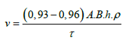
Where A,B- The length and width of the metal bath in the
tundish, m;
h- Depth of immersion of the pipe in metal;
τ-The time need to replace the ladle.
Constructive implementation of vertical and horizontal
movement mechanisms ensures that their independent movements
are possible, ensuring that the funnel is pressed to the slide valve of
the bucket in an open position and the plate is pressed to the seal
in a closed position. The presence on the lid of the vacuum-camera
with a vacuum slide valve provides the possibility of sealing the
vacuum-camera when changing of ladle and slide valve opening at
the beginning of new ladle casting. Connecting of sluice camera with
the vacuum pipeline and atmosphere makes it easier to disconnect
the ladle when replacing and opening the shutter when the new
bucket is poured. The application of this technical solution ensures
the following feasibility studies:
a. Continuous vacuuming of a series of smelting without
breaking the vacuum;
b. The consumption of inert gas to fill the vacuum chamber
is reduced (instead of filling it at the end of the bottling of each
melting argon is fed into the vacuum chamber only once-at the
end of the casting series);
c. The expenditure for marking and deleting of non-vacuum
metal sections is excluded;
d. The life of the vacuum-camera refractories is increased by
significantly reducing the number of heat-shifters;
e. Heat losses are reduced and the formation of lining
infusions is prevented by the exclusion of vacuum-camera stub
in the casting bottling process.
The reliability and durability of the vacuum pump and vacuumwire elements are improved by reducing pressure fluctuations in the vacuum wire. This technical solution can be applied as by continuous steel casting on the CCM, as when casting large bars of several melts. The technical problems arising from the creation and operation of vacuuming units are quite overcome, and the significant beneficial effect of combining vacuuming and metal casting processes in the conditions of mass steel production in the high-performance converter workshops have significant unrealized potential and real prospects.
References
- Sokolov GA (1983) Stream vacuum treatment of steel casted at CCM. Steel 12: 19-20.
- Parshin VM, Zhavoronkov YI, Protasov AV, Lukovnikov VS (1993) The unit and vacuuming technology with continuous steel casting. The Proceedings of the First Congress of the Steelmakers. Russia, p 237-239.
- Parshin VM, Zhavoronkov YI, Protasov AV, Lukovnikov VS (1993) The steel vacuuming unit for the CCM of the steelworks. Saporizhstal-Bulletin Black Metallurgy 3: 23-25.
- Protasov AV, Revin EM, Parshin VM (1995) The device for streamt vacuuming of steel during the casting process.
- Protasov AK, Revin EM, Korobkov KI (1997).
- Protasov AV, Revin EM, Boyko YP (1995) Metal stream vacuuming device.
- Timofeev VT, Sapozhnikov VN, Moyjim VO, Protasov AV (1995) Metal stream vacuuming device.
- Protasov AV, Revin EM, Boyko YP (1994) Device for stream vacuuming steel in the process of casting.
- Afonin SS, Parshin VM, Larin AV, Protasov AV (1997) Method of vacuuming steel in the process of bottling and the device for its implementation.
- Reshetov VI, Protasov AV, Revin EM (1996) New design of the flow vacuumator: Heavy engineering. 5: 5-6.
- Protasov AB (2010) Actual problems of creating machine-processing units of steel. Low-pressure treatment. Steel 12: 20-26.
© 2021 Protasov AV. This is an open access article distributed under the terms of the Creative Commons Attribution License , which permits unrestricted use, distribution, and build upon your work non-commercially.
Editor In Chief


.jpg)


Signup for Newsletter

Quick Links
 Editorial Board Registrations
 Submit your Article
 Refer a Friend
 Advertise With Us
Our Recent Edition

.jpg)


Top Editors


.jpg)


.bmp)
.jpg)
.png)
.jpg)


.jpg)


.png)

.png)


.png)


Financial Support

Sponsors

Latest e-Books

Latest Video

 a Creative Commons Attribution 4.0 International License. Based on a work at www.crimsonpublishers.com.
Best viewed in
a Creative Commons Attribution 4.0 International License. Based on a work at www.crimsonpublishers.com.
Best viewed in