
- About Us
- Information
-

The Author ensures that the research has been conducted responsibly and ethically with adherence to all relevant regulations. read more..
- For Authors
- For Reviewer
- Manuscript Guidelines
- Membership
- Publication Ethics
-
- Journals
- Reprints
- e-Books
- Videos
- Policies
- Contact Us
 COVID-19
- Submissions


Full Text
Evolutions in Mechanical Engineering
An Investigation into a Spring Based Ankle Joint Designed for Lower Limb Prosthesis
Sayem Hossain Bhuiyan*
School of Mechanical Engineering, Engineering Campus, University of Science Malaysia, Malaysia
*Corresponding author:Sayem Hossain Bhuiyan, Senior Lecturer, School of Mechanical Engineering, Engineering Campus, University of Science Malaysia, Malaysia
Submission: December 14, 2020;Published: March 26, 2021

ISSN 2640-9690 Volume3 Issue3
Abstract
A spring based ankle joint is designed to improve the performance of mechanical type prostheses. The torsional and compression springs with the help of some foot plate arrangement is used to enable the prosthesis in producing desired flexion and extension and also storing and returning energy by the ankle joint during the gait cycle. The motion analysis and Finite-Element Analysis (FEA) of ankle joint components are carried out to assess the feasibility of the design. The FEA results are then compared with the real data obtained from the literature for a similar subject. The pattern of motion analysis results has shown a great resemblance with the gait cycle of a healthy biological limb, and the design is identified to be safe with factory of safety of 1.9 from the FEA results.
Keywords: Prosthesis; Ankle joint; Biomechanics; Kinematics; Kinetics; Finite element analysis
Introduction
The typical prosthetic ankle joints are either hinge type or single piece solid plate type
[1]. These are cheap and robust; however, they have limitation in providing adequate stability
(for hinge type), flexion and extension (for single plate type) to the prosthesis due to their
construction. The advanced type of electronically controlled ankle joints are, therefore,
very good at producing desired movement with enough stability, which are expensive. The
proposed design of an ankle joint will enable the mechanical type of ankle joint overcoming
the limitation of stability, flexion and extension within an affordable price. This will enhance
the range of motion of the mechanical type of prosthesis without incorporating any expensive
electronic devices into the ankle joint. Unlike to the typic al mechanical prosthesis, the new
design will allow the prosthesis to bend forward and backward to any desired angle with
enough stability. In addition to this, the proposed design will enable the prosthesis absorbing
more shocks than any other type of ankle joints available in the market. A spring based ankle
joint will make the prosthesis imitating the movement of the biological limb closely further.
The hip, knee and ankle joints are essentially involved in balancing and controlling
the lower-limb locomotion during different movements in walking. In recent transtibial
amputees, a reduced reliance on the hip strategy and an increased utilization of the ankle
strategy is expected over time during dynamic balancing [2]. The Natural Ankle-Foot System
(NAFS) plays a major role in the performance of human locomotion, contributing to the
maintenance of upright support and generation of forward momentum [3]. The ankle motion
during ground-level walking is quasi-periodic and is usually divided into two main phases:
the stance phase and the swing phase. An ideal gait cycle is typically defined as starting with
the heel strike of one foot and ending at the next heel strike of the same foot. The shape and
duration of the gait cycle varies from step to step and it strongly depends on the gait speed,
subject morphology, subject weight, and terrain conditions [4]. Prostheses are required to
imitate the gait cycle of the healthy biological limb to move in a more natural way. To mimic
unimpaired ankle joint function during gait, prosthetic devices for individuals with Transtibial
Amputation (TTA) must approximate unimpaired ankle Range of Motion (ROM), torque, and
power with similar synchrony and magnitude [5,6]. To recreate the gait cycle movements in
the prosthesis, the ankle joint construction, it kinematics and kinetics are crucially important
[7]. Ankle kinematics indicates the movement of the ankle component in space without
consideration of the forces that cause that movement, whereas the ankle kinetics indicate
the movement and the forces that cause that movement [8]. The stiffness of prosthetic ankle is also identified contributing to balance control [9]. During levelground
steady state walking, the natural ankle joint undergoes a
phase of energy storage or absorption [i.e., negative work done via
eccentric muscle activity] during early to midstance, followed by a
phase of energy generation [i.e., positive work done via concentric
muscle activity] during late stance [10]. The efficiency of the ESR
prostheses depends on the ratio of energy storing and returning
capacity [3,11]. A closer replication of kinematics and kinetics of
natural ankle by the prosthetic ankle joint would make it more
effective. A compression and a torsional spring-based ankle joint
would help to obtain an ESR prosthesis by storing energy during
compression and twisting and releasing during extension and
decoiling respectively. Besides, these springs will help the amputee
to overcome the difficulties in producing required angle of
rotation in their prosthetic feet without affecting the stiffness. The
compression spring at the foot will allow the amputee to absorb
more shock, whereas the torsion spring will enable the ankle
joint to rotate in a controlled way to any desired angle without
demanding any additional setup.
Design of Spring Base D Ankle Joint
The design of the spring-based ankle joint is unlike to any other
ankle joint currently available in the market. The typical mechanical
ankle joints for normal walking are hinge type or fixed type joint,
whereas the ankle joints for running and sprinting are single piece
solid plate type. The newly designed ankle joint is comprised of
number of components-one shank rod, one hinge knuckle, one
bushing pin, two ball bearing, one sleeve bearing, one upper foot
plate, one lower foot plate , one torsional spring, two torsional
spring holder, one compression spring, one compression spring
holder, one compression spring guide and some bolts and nuts. The
lower foot plate and upper foot plate are bolted together at frontal
end and there is a compression spring positioned between two
plates at the posterior end. The compression spring is mounted on
a spring holder attached to the lower foot plate and being held by a
spring guide attached to the upper foot plate from the top.
Due to the shape of the upper foot plate, it acts as a leaf spring.
The foot plates and the compression spring assembly jointly behave
as a shock absorber. At the same time, this assembly acts as an Energy
Storing and Returning (ESR) system for the ankle joint. The hinge
knuckle is mounted on the top of the upper foot plate where the
shank rod is connected to a busing pin and two ball bearings from
two opposite sides. A sleeve bearing is put in between the busing
pin and shank rod connecter hole. This has been done to protect
the busing pin from early damage by heavy load due to the amputee
weight. The torsional spring is placed at the hinge joint of shank rod
and knuckle with the help of two spring holders from two ends. The
torsional spring provides enough stiffness to the ankle joint when
rotate and also can store and return energy during compression
and expansion respectively. In an attempt to replicate the functions
of muscles and tendons in storing and returning energy, ankle joints
are developed by utilizing the elasticity and stiffness characteristics
of spring material, where energy is stored when the material
deforms, and energy is returned when the material returns to its initial shape. Different views of the newly designed spring based
ankle joint are shown in the Figure 1. The ankle-foot system of the
prosthesis is enabled producing flexion at the ankle by introducing
the torsional spring at the joint. The torsional spring of the ankle
joint permit to generates any angle of rotation between 340 and
-150 degrees of flexion, which is usual range of flexion of a healthy
ankle joint [12,13]. The torsional spring movement is maximum
at 340 of rotation, which is zero when the shank is upright. The
compression spring installed in between the foot plates helps to
absorb shocks and store energy during stance phase and return
during swing phase. The mass of the knee-ankle-foot system is
3.5kg. The heel-toe length is 0.3m. The different components of the
spring based ankle joint are shown in the following Figure 2.
Figure 1: Design of ankle joint a) frontal view, and b) isometric view.

Figure 2:The exploded view of the different ankle joint components.

The prosthetic ankle joint has been designed with an aim to upgrade the existing mechanical type of ankle joints, eliminate their limitations and thus to make them serving like a healthy natural ankle joint. The biomechanics of a healthy ankle joint has been imitated with an arrangement of some compression and torsional springs, and some foot plates of leaf spring. A greater range of flexion and extension had been achieved with help of some hinge joint incorporated in the ankle joint. The required stiffness and stability of the ankle joint have been obtained with the torsional spring introduced at the hinge joint of the prosthetic ankle. The shock absorption by the prosthesis has been achieved with the foot plates, and the compression spring placed in-between. The most important phenomenon, which makes a prosthesis moving like a healthy biological limb during walking is the features of Energy Storing and Returning (ESR). This property of ESR has been obtained with the resultant effect of compression and torsional springs. The ESR prosthetic foot absorbs shock and stores energy when loaded and then releases stored energy at push-off. Both the static and dynamic analyses of the ankle joint have been conducted to see the movement of the prosthetic joint. The finite-element analysis of the joint components has been carried out to predict the changes in the mechanical properties of the joint components and also their ability to withstand against the applied load. The viability of the design has been evaluated with a comparative study conducted between the simulation results, and the real data obtained from the literature for a subject with similar anthropometric variables.
Ankle Joint Analysis
The ankle-foot complex plays an important role in human locomotion. The ankle flexor and extensor muscles are crucial to provide vertical support and forward progression of the body. A closer imitation of the flexion and extension movements of the ankle joint would make the prosthesis moving in more natural way. For low speed walking, providing additional energy in ambulation of a prosthesis is not significant; however, for normal and fast walking speeds, providing additional energy by the ankle-foot arrangement for propulsion at the plantar flexion phase is crucially important. A motion analysis of the ankle joint would permit one to see the energy storing and returning capacity of the ankle-foot system and also the ability of the foot in following gait movement during walking.
Motion analysis of ankle joint
Motion analysis of the ankle joint is carried out to see the movements of the ankle-foot assembly and its different components under applied external load. The movements and forces calculated for the ankle-foot system will help to carry out a structural analysis of the ankle components and thus to ensure ankle performance. Two types of analysis are carried out in motion analysis-kinematic analysis and dynamic analysis.
Kinematic analysis: For kinematic analysis of the ankle joint, the angular displacement and angular velocity under applied force and torque are observed, which are then compared with the practical test results to see the deflections. At the stance phase of the gait cycle, no rotation is observed at the ankle joint. Then the entire load acting on the ankle joint is Y-directional, which is the body weight of the amputee, i.e. equal to the body weight of the amputee and the value of applied torque will be zero. However, at the swing phase, the applied load will be the Y-component of the amputee body weight for the accrued angle of rotation during flexion and extension movements, and the value of the applied toque will be the torque due to the X-component of amputee weight for that particular rotation angle. The variables used in the simulation are based on the features of subject, which are tabulated in Table 1. The weight of the subject is
Table 1:Anthropometrical variable of subjects.

𝑊𝑊= 𝑚𝑎=82.2𝐾𝑔∗9.81𝑚⁄𝑠2=806.38𝑁=𝐹=𝐴𝑝𝑝𝑙aa𝑒𝑑 𝑙𝑜𝑎𝑑.
Both the torsional and compression springs play significant role in creating movement at the ankle joint. In ankle joint, the torsional spring carries partial load of the user during swing phase of walking and also when to produce bending movement in the ankle joint, whereas the compression spring carries proportion of load at stance phase of gait cycle. The load applies to the torsional spring=the proportion of amputee weight shared by the torsional spring during swing phase and flexion and extension movements. During swing phase of a biological lower limb, the finger joints help to produce desired rotation in the foot. However, there is no finger joint incorporated in the proposed design, the ankle joint has to yield that movement in the foot arrangement.
The rotation angle varies depending on the mode and speed of walking and also on the type of activities performed. The maximum possible angles of rotation are considered as design parameter for the torsional spring design. Therefore, the forces applied on the spring at those particular angles are casual and cannot consider as dynamic load, and thus should not apply dynamic loading condition during the spring design. The maximum angle of rotation produced by the ankle joint at different phases of gait cycle is shown in (Figure 3). Let’s take the length of torque arm, 𝑙=50𝑚𝑚. In swing phase, the body weight of the amputee is shared by both the sound leg and the prosthesis. The proportion of load shared by the prosthesis and the unimpaired leg vary based on the rotation ankle. However, for sake of simplifying the calculation; the load is considered to be shared equally by the sound limb and the prosthesis. When the shank produces 340 of rotation angle at the ankle joint, a corresponding angle of 560 is produced at the knee joint.
Figure 3: The angle of rotation produced by the ankle joint.

Therefore, the weight component transmitted to the shank from the hip is
𝑃=𝑊𝑊2 cos56=392.4∗cos56=219.4 𝑁
The applied load on the torsional spring arm at 340 clockwise rotation is
𝐹1=𝑃sin34=219.4∗sin34=122.7𝑁
The applied load on the torsional spring arm at 150 anticlockwise rotation is
𝐹2=𝑃sin(−15)=219.4∗sin(−15)=−56.78𝑁
The toque at counterclockwise direction,
𝑀𝑚𝑎𝑥=𝑀1=𝐹1×𝑙=122.64×50=6132𝑁. 𝑚𝑚 (𝑎𝑛𝑡i𝑐𝑙𝑜𝑐𝑘𝑤i𝑠𝑒)
The toque at counterclockwise direction,
𝑀mi𝑛=𝑀2=𝐹2×𝑙=−56.78×50=−2839𝑁.𝑚𝑚, (𝑜𝑟 2838.0𝑁.𝑚𝑚, 𝑐𝑙𝑜𝑐𝑘𝑤i𝑠𝑒)
Total angle of rotation, 𝜃𝜃= (𝜃𝜃−𝜃𝜃2)=34°−(−15°)=49°
In simulation, the springs are substituted by setting the connections between the components from the two ends of the spring as spring joint where the spring constant/spring rate is used same as of the replaced spring. Therefore, the spring constants/spring rates need to be calculated in order to input to the simulation. This has been done to simplify the simulation and reduce the simulation time. The spring constant (spring rate/turn) for the torsional spring is 𝑘=66.27𝑁. 𝑚𝑚/𝑡𝑢𝑟𝑛. For the ankle-foot assembly, the load is also shared by the compression spring when standing. The purpose of the compression spring is to absorb the load during stance phase and return it during swing phase. Therefore, the moments, force and torque are to be calculated for the cumulative weight of the prosthesis and the subject.
Figure 4:The load distribution in the prosthetic foot.

Since the compression spring is located between the upper
foot plate and the lower foot plate, the initial applied load is the holding force used by these foot plates. The final applied load
to the compression spring is the load due to the amputee body
weight. The weight of the prosthesis is considered to be balanced
by the weight of the amputated limb. Let’s take, the weight of the
Above Knee (AK) prosthesis=3.5Kg, which is average weight of
the above knee prosthesis available in the market. The load due to
the amputee weight is, W=(82.2*9.81)=806.38N has to be shared
by the compression spring and the foot plates. The force/load
distribution on the foot plates and the compression spring is shown
in the following Figure 4.
Therefore,
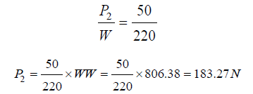
𝐹i𝑛𝑎𝑙 𝑙𝑜𝑎𝑑, 𝑃2 =𝑙𝑜𝑎𝑑 𝑑𝑢𝑒 𝑡𝑜 𝑡ℎ𝑒 𝑤𝑒i𝑔ℎ𝑡 𝑝𝑟𝑜𝑝𝑜𝑟𝑡i𝑜𝑛 𝑠ℎ𝑎𝑟𝑒𝑑 𝑏𝑦 𝑡ℎ𝑒 𝑐𝑜𝑚𝑝𝑟𝑒𝑠𝑠i𝑜𝑛 𝑠𝑝𝑟i𝑛𝑔=183.27𝑁
𝑆𝑝𝑟i𝑛𝑔 𝑟𝑎𝑡𝑒, 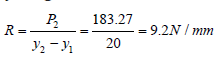 𝑤ℎi𝑐ℎ i𝑠 𝑠𝑝ri𝑛𝑔 𝑟𝑎𝑡𝑒 𝑘
𝐼𝑛i𝑡i𝑎𝑙 𝑙𝑜𝑎𝑑, 𝑃1=𝑙𝑜𝑎𝑑 𝑡ℎ𝑎𝑡 𝑐𝑎𝑢𝑠𝑒𝑠 𝑡ℎ𝑒 𝑠𝑝𝑟i𝑛𝑔 𝑡𝑜 𝑑 𝑒𝑜𝑟𝑚 10𝑚𝑚 𝑜𝑜𝑟𝑜𝑚 𝑡ℎ𝑒 co𝑟𝑒𝑒 𝑙𝑜𝑎𝑑 𝑐𝑜𝑛𝑑i𝑡i𝑜𝑛=𝑅×𝐿𝑓𝑓−1=9.2∗5=46𝑁 Therefore,
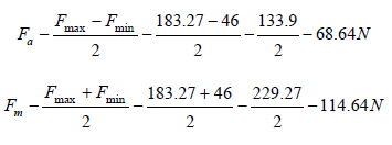
Where, 𝐹𝑚𝑎𝑥 =𝑃2, 𝑎𝑛𝑑 𝐹𝑚i𝑛 =𝑃1, 𝑦𝑚𝑎𝑥=20, 𝑎𝑛𝑑 𝑦𝑚i𝑛=5
The resultant effect of the torsional and compression springs influences the movement of the prosthesis during the gait cycle. The angular displacement of the ankle joint at different phases of gait cycle is shown in Figure 5. From the (Figures 5 & 6), the angular position of the shank is 0° when standing, which vary between 34° and -15° at different phase of the gait cycle. (Figures 5a-5e) show the different angular position of the shank while producing angular displacement from 0° to 34°. The corresponding angular displacements are represented in the graph of the same (Figures 5g-5j). (Figures 6a-6e) show the different angular position of the shank while producing angular displacement from 0° to -15°. The corresponding angular displacements are represented in the graph of the same (Figure 6g-6j). From the (Figure 5g-5j) and (Figure 6g-6j), the patterns of the angular displacement graphs are quite similar; therefore, any of these angular displacement graphs can compare with the ankle joint graph obtained from the healthy subject.
Figure 5:Angular position of shank when bending forward.

Figure 6: Angular position of shank when bending backward.

The (Figure 7a) represents the changes of ankle angle of a healthy biological lower limb during the swing phase, whereas (Figure 7b) shows the angular displacement of the shank of the prosthetic ankle joint for the same phase. From these figures, the pattern of changing the ankle angle (Figure 7a) is quite similar to the pattern of the fragmented graph marked in a rectangular window of (Figure 5b). Though, the angles of rotation are not same, the patterns of the graphs are observed to be identical. This is because the angle of rotation varies based on walking speed, stepping length/stride length, etc.; however, they still maintain a similar trend throughout the swing phase. Therefore, it can be deduced that the proposed spring based ankle joint is capable of reproducing the movement of a healthy biological ankle joint effectively. There are also significant changes in the pattern of ankle velocity during the swing phase. The Figure 8 shows the similarity or dissimilarity between the patterns of velocity graphs obtained from the data recorded from the healthy subject and the motion analysis result. The graph of (Figure 8a) is plotted based on the real data recorded from the healthy subject whereas the graph of (Figure 8b) is obtained from the motion analysis data. From the (Figure 8), the pattern of the angular velocity graph has large similarity with the pattern of the velocity graph marked inside the rectangular window. Though the amplitudes of the graphs are not same, they fluctuate following a common trend. There is some deflection in the amplitudes of ankle velocity is appeared on the graphs; it is because maintaining a particular ankle velocity throughout the gait is not usually happened. However, during simulation, a particular ankle speed was maintained to simplify the calculation. On the other hand, both the patterns are sinusoidal; however, there are some phase differences, which can be attributed to the fact of different rates of velocity. Since, the similar velocity wasn’t maintained during simulation and subject’s walking, there is some phase difference exists between the velocity graphs obtained from real data and from the motion analysis.
Figure 7: Ankle joint angle throughout the swing phases a) obtained from healthy subject, and b) obtained from motion analysis of the prosthetic ankle joint.

Figure 8:Angular velocity of the ankle joint a) obtained from healthy subject, and b) from motion analysis of the prosthetic ankle joint.

Dynamic analysis
The forces generated by movement as well as the movements themselves are evaluated by the dynamic analysis. The joint moment graph plotted with the real data (recorded from the subject) can compare with the reaction moment curve obtained from the motion analysis of the ankle joint. The performance of the prosthetic ankle joint can be evaluated with the results of this analysis. From the (Figure 9), the pattern of the joint moment is not absolutely sinusoidal whereas the joint moment graph based on simulation data is sinusoidal. There is some disturbance in the sinusoidal shape of the joint moment graph due to the respective change in the ankle biomechanics. However, no such disturbance is observed on the reaction moment graph of the prosthetic ankle joint; this is because there is no disturbance applied on to the ankle joint during the simulation to make the analysis simpler. Though, the natures of the graphs are not identical, the joint moment graph obtained from the real data, and the reaction moment curve from the dynamic analysis results maintain a similar trend [marked in the rectangular window]. The magnitude of variation in both the graphs also varies at different stages of ankle rotation during the swing phase. The joint power is another important factor to look into during the dynamic analysis. The fluctuation of joint power during the swing phase is shown in the Figure 10.
Figure 9:Ankle joint moment throughout the swing phase a) obtained from healthy subject, and b) from motion analysis of the prosthetic ankle joint.

Figure 10:Ankle joint powers throughout the swing phase a) obtained from the healthy subject, and b) from motion analysis of the prosthetic ankle joint

From the (Figure 10), the joint power at the different point of swing phase varies both in positive and negative directions. The positive curve of the power graph represents the power generation by the ankle joint whereas the negative curve shows the power absorption by the joint. From the (Figure 10a), the pattern of the joint power curve produced from the real data is sinusoidal with a non-uniform magnitude. The pattern of the joint power curve (Figure 10b) obtained from the dynamic analysis of the ankle joint is found having a similar trend. Even though, the magnitude of the joint power is not same, the pattern of the power curve of (Figure 10a) is similar to the pattern of the power curve marked in the rectangular window of (Figure 10b). Due to the difference between the boundary conditions used for collecting data from the subject and simulation, there is some phase difference exists in the graphs. However, they are found to maintain a similar trend throughout the swing phase.
Finite Element Analysis of Ankle Joint Components
Finite-Element Analysis can efficiently optimize and validate each design step; it can ensure quality, performance, and safety. SOLIDWORKS simulation uses the displacement formulation of the finite-element method to calculate component displacements, strains, and stresses under internal and external loads. The analysis of components is carried out by linear stress analysis. It was done to ensure the geometry remains in the linear elastic range [that is, once the load is removed; the component returns to its original shape]; then linear stress analysis is applied, as long as the rotations and displacements are small relative to the geometry. For such an analysis, factor of safety [FoS] is a common design goal. First of all, a model has to be created to perform a finite-element analysis. Several papers published elsewhere have already been focused on creation of a finite-element model either of a joint itself [knee joint, ankle joint, hip joint, temporo-mandibular joint, etc.] or of an implant [14,15]. To create a finite-element model, boundary conditions have to set at the first place; the mesh formation is to do next, and finally the simulation has to run to get the results. The detail of the ankle is given below:
Model setup
To set up a model, connections between the components, component contacts, fixtures and external load are the primary factors to be defined accurately. The whole ankle assembly is defined as global contact, where the contacts between the shanksleeve bearing is set as roller sliding contact; sleeve bearingbushing pin as fixed hinge joint; knuckle-bushing pin as bearing support connection. The connections between the components like shank-knuckle, and upper foot plate- lower foot plates are assigned as spring connection. The inner face of bearing hole of the knuckle frame and the outer face of the ball bearing are defined as bonded contact. The contacts between knuckle and upper foot plate, upper foot plate and spring guide, and lower foot plate and spring holder are defined as fixed geometry. The lower foot plate is set up as fixed geometry whereas the face between upper foot plate and lower foot plate is defined as a roller slider joint. Both the normal force and torque are applied as external load on to the shank tip. Solid curvature based high quality 16 Jacobian points mesh is formed. The minimum element size of the mesh is 12.4822mm where the maximum element size of the mesh is 2.49643mm. Total node in the meshed model is 46316; total element in the model is 25763 where the maximum aspect ratio is 7.9333. All components are considered to be the solid body. The Aluminum 1060 Alloy is chosen for all components except the sleeve and ball bearing, and also the bushing pin, for which AISI 1020 cold-rolled steel is selected. The model of the ankle joint of (Figure 11a) shows all the boundary conditions and the external loads applied to the different component, and (Figure 11b) illustrate s the meshing of the ankle components.
Figure 11: a) Model of spring based ankle joint, b) Solid mesh of the model.

Finite element analysis results
In the finite-element analysis, the stress, strain and displacement of the ankle joint components are studied to check the viability of the design. In most of the engineering design, the maximum von Mises stress is calculated as a mean of design safety. The maximum von Mises stress criterion is based on the von Mises-Hencky theory, also known as the Shear-energy theory or the Maximum distortion energy theory. In terms of the principal stresses σ1, σ2, σ3, the von Mises stress is expressed as:
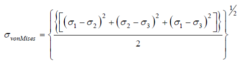 [1]
[1]
The theory states that a ductile material starts to yield at a location when the von Mises stress becomes equal to the stress limit. The yield strength is generally used as the stress limit.
𝜎𝑣𝑜𝑛𝑀i𝑠𝑒𝑠 >=𝜎𝑙i𝑚i𝑡 [2]
Yield strength is a temperature-dependent property. This specified value of the yield strength should consider the temperature of the component. The factor of safety at a location is calculate d from:
Factor of Safety, (𝐹𝑜𝑆)=𝜎𝑙i𝑚i𝑡⁄𝜎𝑣𝑜𝑛𝑀i𝑠𝑒 [3]
The von Mises stress of different ankle components found from the finite element analysis are shown in Figure 12. The primary focus of von Mises stress analysis is on the condition of plastic stability. From the von Mises stress calculations it is evident that the maximum stress value of 14.8804MPa achieved during the analysis (Figure 12) does not exceed the PEEK material yield strength of 27.57MPa [according to material properties of 1060 Aluminum Alloy]. The factor of safety is 27.57/14.88=1.9, which is sufficient to ensure the design safety. Therefore, no plastic deformation of the ankle joint components occurred, and the condition of plastic stability was conformed.
Figure 12: A von Mises stress of different components of ankle joint.

The main focus of work was to design an ankle joint FE model and to confirm its functionality; for this purpose, the Solidworks software was used. The model was validated using previously obtained experimental data [14]. The experimental and predicted data are compared in (Figures 7-10) where it can be seen that the experimental data of ankle angle progression during knee- bending is in a good correlation with the data obtained from simulation. The equivalent strain or the von Mises equivalent strain is a scalar quantity, which is another important factor for the design and is often used to describe the state of strain in solid components. The equivalent strain is commonly defined on plasticity, which is expressed as following.
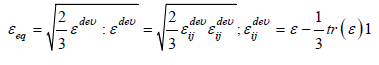 [4]
[4]
This quantity is work conjugate to the equivalent stress defined as
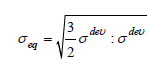 [5]
[5]
The equivalent strains of different components of ankle joint
are shown in the Figure 13. From the equivalent strain calculations,
it is obvious that the maximum strain occurred during the analysis
is 5.37992e-005 (Figure 13), which is insignificant to be appeared
as distortion on the shape of component and therefore, can be
neglected. Hence the components of the ankle joint have met
the condition of rigidity. The displacement analysis allows one
to assess the displacement and reaction force results for static,
nonlinear, dynamic, drop test studies, or mode shapes for buckling
and frequency studies. The results of static displacement studies
are shown in the following (Figure 14). From the (Figure 14), the
maximum static displacement of different ankle joint components
during analysis is 27.6102mm, which is considerable in magnitude.
However, the magnitude is still lower than the maximum
displacement allowable by the material (maximum displacement
occurred at the shank rod, which is 74mm for the design dimension)
used for the components before rupture. Therefore, the design has
complied the condition of stiffness as well. In addition to this, the
elastic property of the spring materials helped the ankle - foot
arrangement to store and return energy during the gait cycle. Since
the springs in the ankle - foot arrangement has been substituted
with some spring constants of the same value; the FEA of the
springs was not performed in the simulation. The finite-element
analysis results of other ankle joint components were obtained for
the equivalent spring constant and for the spring life of 107 cycles.
The entire results for the ankle joint components obtained from the
FEA show that the components are safe.
The life cycle used in the simulation is quite big, which indicates
the springs are good enough to store and return energy effectively
for long without experiencing any fatigue failure. From the finiteelement
analysis, the maximum von Mises stress, equivalent strain
and displacement of the components occurred during the gait cycle
movement of the ankle joint are found to remain quiet below than
the material yield strength, permissible strain and displacement
limits respectively. Therefore, the proposed design is safe for the
particular application, and no unexpected failure will take place.
Figure 13: Strain analysis of ankle joint components.

Figure 14: Displacement analysis of ankle joint components.

Conclusion
Though the proposed spring based ankle joint designed for a transfemoral amputee still can be improved in terms of shape and dimension, it is found capable of recreating gait cycle movement of a healthy biological limb with adequate safety. According to the motion study results, the prosthetic ankle joint is capable of producing desired flexion and extension at the ankle joint and thus can enable the prosthesis to imitate the biomechanics of the missing limb without any difficulty. At the same time, the spring based ankle-foot arrangement allows its users to store and return energy, and also to act like a shock absorber when needed. The finiteelement analysis result shows that the prosthesis components has minimal factor of safety of 1.9, which is safe enough to be used by the particular subject.
Acknowledgement
The authors would like to thank the University of Science Malaysia and University of Malaya for proving the research facilities, and also the Ministry of Education Malaysia for supporting with the grant no: UM.C/625/HIR/MOHE/ENG/35 to carry out this work.
Funding
The Ministry of Education Malaysia have supported this work with grant no: UM.C/625/HIR/MOHE/ENG/35.
References
- Sagawa Y, Turcot K, Armand S, Thevenon A, Vuillerme N, et al. (2011) Biomechanics and physiological parameters during gait in lower-limb amputees: A systematic review. Gait & Posture 33(4): 511-526.
- Barnett CT, Vanicek N, Polman RCJ (2013) Postural responses during volitional and perturbed dynamic balance tasks in new lower limb amputees: A longitudinal study. Gait & Posture 37(3): 319-325.
- Takahashi KZ, Stanhope SJ (2013) Mechanical energy profiles of the combined ankle-foot system in normal gait: Insights for prosthetic designs. Gait & Posture 38(4): 818-823.
- Jiménez Fabián R, Verlinden O (2012) Review of control algorithms for robotic ankle systems in lower-limb orthoses, prostheses, and exoskeletons. Medical Engineering & Physics 34(4): 397-408.
- Ferris AE, Aldridge JM, Rábago CA, Wilken JM (2012) Evaluation of a powered ankle-foot prosthetic system during walking. Archives of Physical Medicine and Rehabilitation 93(11): 1911-1918.
- Devan H, Hendrick P, Ribeiro DC, Hale LA, Carman A (2014) Asymmetrical movements of the lumbopelvic region: Is this a potential mechanism for low back pain in people with lower limb amputation? Medical Hypotheses 82(1): 77-85.
- Rajťúková V, Michalíková M, Bednarčíková L, Balogová A, Živčák J (2014) Biomechanics of lower limb prostheses. Procedia Engineering 96: 382-391.
- Barton T, Lintz F, Winson I (2011) Biomechanical changes associated with the osteoarthritic, arthrodesed, and prosthetic ankle joint. Foot and Ankle Surgery 17(2): 52-57.
- Curtze C, Hof AL, Postema K, Otten B (2012) The relative contributions of the prosthetic and sound limb to balance control in unilateral transtibial amputees. Gait & Posture 36(2): 276-281.
- Russell Esposito E, Wilken JM (2014) Biomechanical risk factors for knee osteoarthritis when using passive and powered ankle-foot prostheses. Clinical Biomechanics 29(10): 1186-1192.
- Ventura JD, Klute GK, Neptune RR (2011) The effects of prosthetic ankle dorsiflexion and energy return on below-knee amputee leg loading. Clinical Biomechanics 26(3): 298-303.
- Kapoor A, Mishra SK, Dewangan SK, Mody BS (2008) Range of movements of lower limb joints in cross-legged sitting posture. The Journal of Arthroplasty 23(3): 451-453.
- Larsen KL, Maanum G, Frøslie KF, Jahnsen R (2012) Ambulant adults with spastic cerebral palsy: The validity of lower limb joint angle measurements from sagittal video recordings. Gait & Posture 35(2): 186-191.
- Zach L, Kunčická L, Růžička P, Kocich R (2014) Design, analysis and verification of a knee joint oncological prosthesis finite element model. Computers in Biology and Medicine 54: 53-60.
- Morgenroth DC, Segal AD, Zelik KE, Czerniecki JM, Klute GK, et al. (2011) The effect of prosthetic foot push-off on mechanical loading associated with knee osteoarthritis in lower extremity amputees. Gait & Posture 34(4): 502-507.
© 2021 Sayem Hossain Bhuiyan. This is an open access article distributed under the terms of the Creative Commons Attribution License , which permits unrestricted use, distribution, and build upon your work non-commercially.
Editor In Chief


.jpg)


Signup for Newsletter

Quick Links
 Editorial Board Registrations
 Submit your Article
 Refer a Friend
 Advertise With Us
Our Recent Edition

.jpg)


Top Editors


.jpg)


.bmp)
.jpg)
.png)
.jpg)


.jpg)


.png)

.png)


.png)


Financial Support

Sponsors

Latest e-Books

Latest Video

 a Creative Commons Attribution 4.0 International License. Based on a work at www.crimsonpublishers.com.
Best viewed in
a Creative Commons Attribution 4.0 International License. Based on a work at www.crimsonpublishers.com.
Best viewed in