- Submissions

Full Text
Evolutions in Mechanical Engineering
Computer Controlled Profile Cutting Machine Design and Prototype Manufacturing
Fuat Kartal* and Abdurrezzak Boz
Faculty of Engineering and Architecture, Mechanical Engineering Department, Turkey
*Corresponding author:Fuat Kartal, Faculty of Engineering and Architecture, Mechanical Engineering Department, Turkey
Submission: July 11, 2019;Published: September 18, 2019

ISSN 2640-9690 Volume3 Issue1
Abstract
In this study, a full factorial experimental design technique was applied to determine the optimum feed rate and cutting depth of the workpiece processed by CNC profile cutting machine. As the machining parameters, the lateral burr height, cutting time and the amount of wear on the cutting wheel depending on the feed rate and cutting depth were investigated and found statistically in Minitab 18 package program. In order to compare the cutting times of the profile cutting machines and CNC profile cutting machines used today, time tracking was made. By applying the full factorial method, a total of 25 experiments was carried out in 5 and 5 levels, respectively, as feed rate and cutting depth factors. As a result of the experiment, it was determined that the cutting depth had more effect on the wear on the cutting stone than the feed rate.
Keywords: Profile cutting; CNC; Cutting stone; Cutting time; Grinding
Introduction
Computer numerical control is a modern concept in the manufacturing and manufacturing industries. However, the concept of CNC is based on the basic idea or numerical control of the NC. The idea of numerical control began when the automation of machine tools initially contained very specific concepts of programmable logic. Initially, the first NC machines were built back in the 1940s. In the 1950s, some more advanced machines appeared. These manufacturing machines are based on existing vehicles modified with engines designed to move the controls of the machine. These checks followed certain points fed to the machine with perforated tape. These early mechanisms were soon developed in both analog and digital computers. The introduction of computer technology into the concept of numerical control has led to what we now know as computer numerical control [1,2]. Following the discovery of unalloyed and alloyed tool steels, the discovery of Taylor speed steels and hard carbide tool steels led to the birth of NC, DNC, CNC machines. The automation system has been expanded and the optimization cycle has been started [2,3]. After the World War II, John Parsons sought to improve the plane by creating hardened leather for them. This led to a number of important Air Force research projects conducted at the Massachusetts Institute of Technology (MIT). This research began in 1949. After early planning and research, an experimental milling machine was designed at MIT. Professor JF Reintjes and his research team were involved in this project. [3,4]. Today, the cutting speed of the machines used for profile cutting is made irrespective of the depth of cut and eye decision. With the CNC profile cutting machine which is manufactured and manufactured, parameters such as feed rate and cutting depth can be controlled in computer environments. In this study, the effect of feed rate and depth of cut on the lateral surface burr height, cutting time and abrasion on the cutting wheel was investigated and optimized [5,6].
In this study, prototype design and manufacture of CNC profile cutting machine has been performed and machine working tolerances have been tested and calibration has been performed successfully. Cutting wheels are cheaper and faster than cutting tools used in other cutting operations. The effect of feed rate and depth of cut on the life of the cutting wheel was investigated. Cutting was performed at a constant 90 ° right angle.
Materials and Methods
Computer controlled profile cutting machine
CNC Profile cutting machine consists of Kart X “and “Y” axes in Cartesian coordinate system. With the drive provided by stepper motors, ball screw, ball screw nut, Delrin bearing wheels enables linear movement in axes. The main body of the machine consists of sigma profiles as shown in Figure 1. The grinding machine used has a cutting capacity of 11000RPM. Cutting the wheel diameter maximum 115mm is used. Machine Working capacity is 450mmx450mm. With the help of the G-Code created according to the dimensions of the workpiece, Machon can perform autonomous cutting without touching.
Angle grinding machine
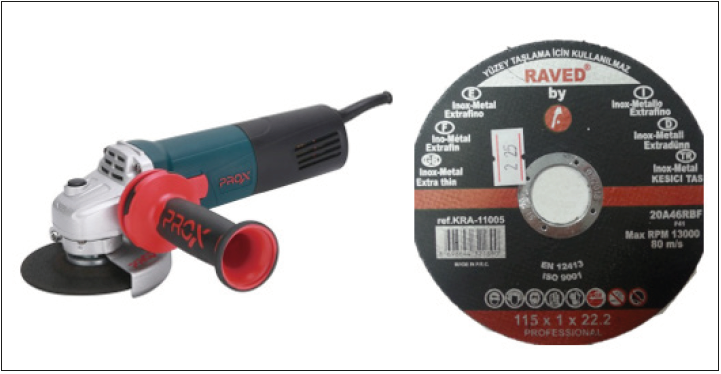
Individual users in one-off transactions usually use it. Due to its portability, it is widely used in the market. The palm grinder used in the application in Figure 2 has a capacity of 115mm cutting stone at a maximum speed of 11000 rpm. In this study, it has the same features as the grinding machine used in CNC profile cutting machine.
Figure 1:Computer controlled profile-cutting machine.

Figure 2:Angle grinder and cutting stone.
Profile cutting machine
Profile cutting machine can cut at a constant 90 °. The device used in the embodiment of Figure 3 can cut at 3800rpm. The maximum cutting wheel diameter is 355mm.
Cutting time measurement for Profile Cutting Machines
Cutting time tracking shall be made for the angle grinder, profile cutting machine and CNC profile cutting machine designed and produced. Table 1 shows the test parameters of the machines to be used in the application. Cutting time, for the profile to be cut, the marking will be terminated by performing a clamping-cutting operation. The feed rate and cutting depth of machines other than CNC profile cutting machines are not known by hand. Aluminum 40x20mmdimensions box (rectangular) profile cutting was made (Table 1).
Figure 3:Profile cutting machine.

Table 1:Parameters of machines used in time tracking.

Full factorial test method and parameters
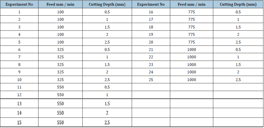
The full factorial method was used to simultaneously investigate the main effects and interaction effects of two or more factors [3]. The 25 tests were performed in the test setup with 5 and 5 levels, respectively, with the test parameters A and B factors specified in Table 2. The test setup for the analysis of the cutting time, lateral burr height and abrasion of the cutting stone at different feed rates and cutting depth of the manufactured CNC profile-cutting machine is as indicated in Table 3. After the test, cutting time, abrasion amount and lateral burr height measurements was investigated (Table 2).
Table 2:Test parameters, levels and desired outputs.

Table 3:Full factorial experimental setup and ranking.
CNC profile cutting machine cutting movement
The cutting method shown in Figure 4 is the cutting method used for all experiments on CNC profile cutting machine. The is the point (0,0) of the work piece. Before the cutting operation, the distance of the cutting depth has been left in order to reach a sufficient number of revolutions. d: Cutting depth, L: Cutting length.
Lateral burr height and measurement
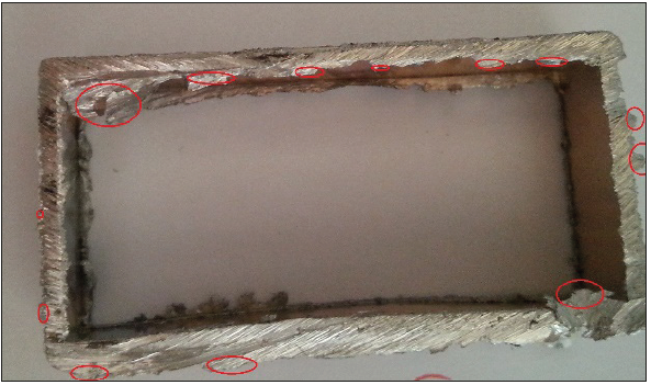
The lateral burr height is the distance from the main part to the melting aggregates at the edges of the profile caused by friction on the cutting surface. In each experiment, the maximum lateral burr height was measured with a caliper. Figure 5 shows the locations where measurements were made.
Figure 4:Cartesian coordinate representation of the go-and-go movement.

Figure 5:Lateral burr height measurement locations.
Wear amount and measurement
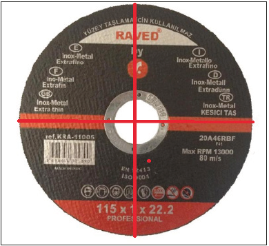
The amount of wear is the reduction in the diameter of the cutoff wheel after cutting. Measurements were made before and after cutting with the help of caliper. As shown in Figure 6, measurements were made from two different points and the average of these measurements was found to be the amount of wear.
Figure 6:Measurement of abrasion on cutting wheel.
Result and Discussion
The cutting time of the CNC profile-cutting machine and the profile cutting machines used in the other market were compared and the data in Table 4 was obtained. Within the scope of the study, the feed rate and cutting depth indicated in Table 3 are variable parameters. The speed was kept constant at 11000rpm. In order to minimize cutting time, minimizing the lateral burr height and minimizing the amount of wear after cutting on the cutting stone, the experimental data were optimized. The size of the aluminum profile cut in each test number is 40x20mm. Mach3 card and Mach3 interface program with the help of the G code is sent by cutting. Following the test set out in Table 3, 25 cuts were made. Diameter distance was measured with the help of caliper by measuring the amount of wear on the cutting wheel. The maximum lateral burr height was measured with a caliper. Outputs are given in Table 5. As a result of full factorial experimental analysis, optimum cut-off parameter according to triple factor was found in Table 6 (Figures 7-9).
Table 4:40x20mm Al profile cutting time for different machines.

Table 5:Test results for 40x20mm aluminum box profile.
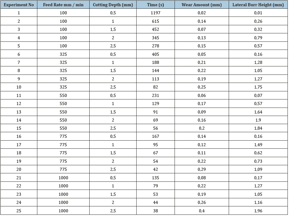
Figure 7:CNC profile machine after cutting parts and cutting surface.

Figure 8: Angle grinder machine with cut piece and cutting surface.

Figure 9: Profile cutting machine with cut piece and cutting surface.

Table 6:Optimum cutting parameter for wear, cutting time, lateral diameter height.

When we examine Figure 9, it is seen that the melting agglomeration is the highest on the cutting surface of the profile cutting machine with the highest speed. The large number of revolutions and the surface of the cutting stone caused more heat to be released, causing the masses to cut on the surface. It is necessary to clean the cutting surface by grinding with additional process. 90-degree right angle has been successfully cut to desired dimensions. Cutting time was 44 seconds. In Figure 8, the cutting surface of the part connected to the cutter on the palm grinder could not be fully cut. Cutting time was 90 seconds. Additional burr cleaning on the cutting surface is required. In Figure 7, the cutting time on the CNC profile-cutting machine lasted 41 seconds. The lateral burr height was the least cut (Table 5; Figures 10-12).
Figure 10:Influence graph of the main factors for wear on the cutting wheel.
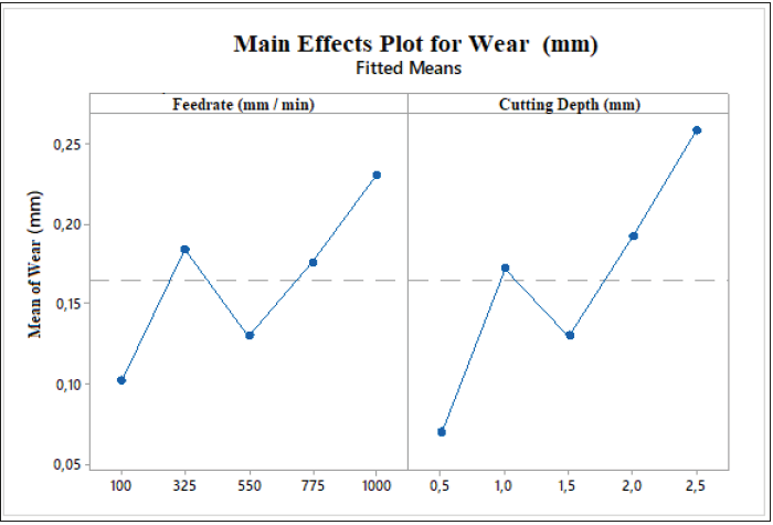
Figure 11:Influence graph of the main factors for lateral burr height.
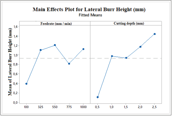
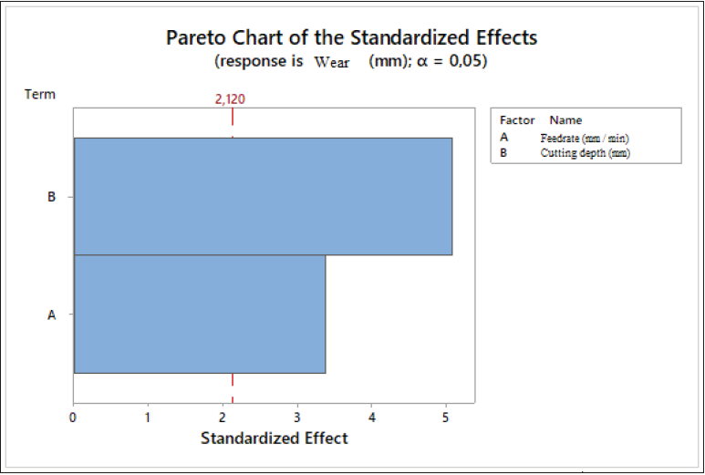
Figure 12:Coefficient of influence of main factors on wear.
Under optimum conditions, the cutting time is 167 seconds, the lateral burr height is 0.14mmand the wear amount is 0.16mm. No additional cleaning and grinding are required. Cutting surface quality under optimum cutting conditions is shown in Figures 13 & 14.
In Figure 15, at a feed rate of 1000mm/min, the lateral burr height was 1.27mm with a cutting depth of 1mm and the lateral burr height 1.96mmwith a cutting depth of 2.5mm. As the cutting depth increases, the lateral burr height increases. In Figure 16, the cutting depth was 2.5mm at a feed rate of 775mm/min, while the lateral burr height was 1.09mm. When we compare the cutting surface at a cutting depth of 550mm/min, 325mm/min, 100mm/ min for feed rate, the lateral burr height was measured as 1.84, 1.75, 0.57mm, respectively, and the difference between them was shown in Figures 17-19. It indicated. The lowest abrasion and lateral burr height were measured at a feed rate of 100mm/min and a cutting depth of 0.5mm. The cutting surface is shown in Figure 19. Although it has the lowest abrasion and lateral burr height, it is not preferred for optimization because the cutting time is 1197 seconds.
Figure 13:Part cut surface in optimum conditions.
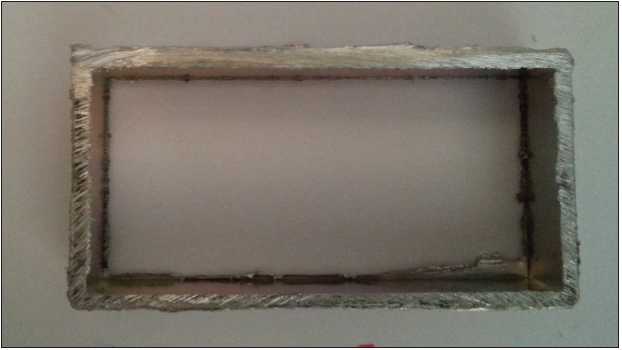
Figure 14:Effect of main parameters on cutting time.
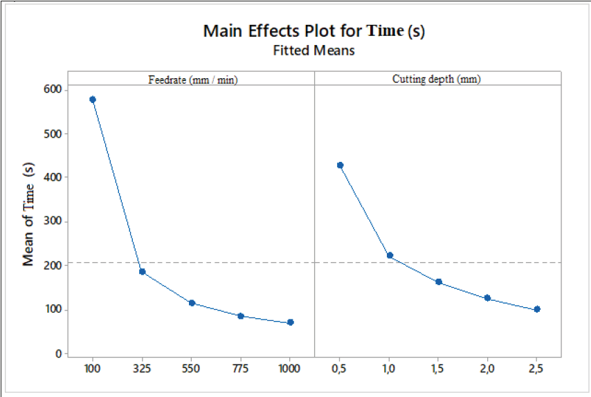
Figure 15:Surface change due to cutting depth at feed rate of 1000mm/min.

Figure 16:Surface change due to cutting depth at feed rate F775mm/min.

Figure 17:Surface change due to cutting depth at feed rate of 550mm/min.

Figure 18: Surface change due to cutting depth at feed rate of 325mm/min.

Figure 19:Surface change due to cutting depth at feed rate of 100mm/min.

The following equations were obtained for the estimation of wear amount and lateral burr height depending on the main parameters as a result of linear regression analysis.
Abrasion = -0.0150 + 0.000110 A + 0.0792 B (1)
Lateral Burr Height = -0,219 + 0,000523 A + 0,572 B (2)
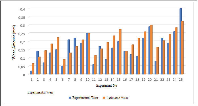
Using the equation (1), the estimated amount of wear was calculated for each test number and a comparison with the actual measured amount of wear is given in Figure 20.
Results
In this study, the effect of the cutting surface on lateral diameter height, cutting stone wear and cutting time change was investigated statistically by using full factorial method.
The comparison of the cutting time of the profile cutting machines and the CNC profile cutting machines that are manufactured and produced are made.
The following results can be drawn from the experiments and statistical calculations;
1. As a result of the analysis, the cutting time is shorter as the feed rate and depth of cut increases in Figure 14.
2. Figure 10 shows that as the cutting depth increases, the amount of wear on the cutting wheel increases.
3. It has been determined that the optimum cutting parameter feed rate is 775mm/min and the cutting depth is 0.5mm by keeping cutting time, abrasion amount and lateral burr height to a minimum.
4. Compared to profile cutting machines and CNC profilecutting machines in the market, cutting process was realized with palm grinding machine at the latest and cutting with the earliest profile cutting machine.
5. Figure 11 shows that the higher the depth of cut, the higher the lateral burr height.
6. It is understood from the data in Figure 12 that the cutting depth affects the wear on the cutting wheel more than the feed rate.
7. In the tests where the cutting depth is high in the cutting stone, regional crater wear is seen. Excessive recesses and protrusions in the cut stone made it difficult to measure the amount of wear. It was observed that the abrasion in the stone was homogeneous at low cutting depths
Figure 20:Estimated wear amount compared to experimental wear amount.
References
- Özdeveci M (2001) Design and manufacture of training type CNC milling.
- Çelik YH, Özek Çelik C (2011) Investigation of the effects of machining parameters on cutting quality in CNC plasma cutting. In 6th International Advanced Technologies Symposium, Elazığ,Turkey, p. 65.
- Kibrit Çioglu A (1998) Company and product quality: What is it? Why is it important ?. Future's Technologies 51: 52-56.
- Sarıışık G, Özkan E (2017) Statistical analysis of shear forces and specific shear energy in CNC machining of marbles. Journal of Science and Engineering 19(55).
- Unrelated H, Çetinkaya K (2010) CNC mıllıng traınıng set desıgn and applıcatı Süleyman Demirel University, International Journal of Technological Sciences 2(3): 53-71.
- Güleryüz B (1999) Programming and construction principles in CNC lathes.
© 2019 Fuat Kartal. This is an open access article distributed under the terms of the Creative Commons Attribution License , which permits unrestricted use, distribution, and build upon your work non-commercially.
 a Creative Commons Attribution 4.0 International License. Based on a work at www.crimsonpublishers.com.
Best viewed in


.jpg)


 Editorial Board Registrations
 Submit your Article
 Refer a Friend
 Advertise With Us
.jpg)


.jpg)


.bmp)
.jpg)
.png)
.jpg)


.jpg)


.png)

.png)


.png)


