- Submissions

Full Text
Evolutions in Mechanical Engineering
Equal Channel Angular Pressing (ECAP): Die Design, Processing Handicaps and Mechanical Characterization
Reham Reda*
Faculty of Engineering, Suez University, Egypt
*Corresponding author:Faculty of Engineering, Suez University, Suez 43721, Egypt; Email: Reham.Reda@suezuni.edu.eg
Submission: April 25, 2019; Published: May 24, 2019

ISSN 2640-9690 Volume2 Issue5
Abstract
ECAP is an efficient processing technique to produce materials with enhanced mechanical properties without any dimensional change. The current work deals with ECAP as a promising processing technology. This paper describes ECAP in terms of die design and manufacturing, processing procedure and handicaps. Finite element analysis using Abaqus CAE 14 program was utilized to reach the optimum safe ECAP die design. In addition, three ECAP passes were implemented on a commercially pure 1100 aluminum alloy, the effect of ECAP on the tensile properties were also demonstrated. Results show that Abaqus program is an excellent tool to optimize the ECAP die design and to attain a low cost and safe design. There are many handicaps arise during ECAP processing that should be taken in considerations in the future work, such as: die fixation system and lubrication procedure. Tensile testing results show that yield and ultimate strength, elongation, strength-ductility balance of 1100 Al alloy increase as the number of ECAP passes increase.
Keywords: ECAP; Die design and manufacturing; Abaqus analysis; Al-processing; ECAP processing handicaps; Tensile properties
Introduction
The need for high strength-lightweight metallic materials increases every day in order to meet the market needs in various applications. This goal can be achieved either by evolving of new materials or by developing existing materials. Development of already existing materials requires emerging upgraded processing techniques. Severe Plastic Deformation (SPD) processing techniques have become important in recent years because of the potential for achieving remarkable grain refinement and enhancing the mechanical properties [1-6]. SPD includes many methods of metal forming, such as: Equal Channel Angular Pressing (ECAP), High Pressure Torsion (HPT), Accumulative Roll-Bonding (ARB), Cyclic Extrusion and Compression (CEC), and Repetitive Corrugation and Straightening (RCS) [3,7].
All SPD methods involve applying of an intensive hydrostatic pressure to induce a very high plastic shear strain on a bulk material without any considerable change in the dimensions by using special tool geometries that prevent free flow of the material [1,5,7].
ECAP is one of the most promising SPD processing techniques for metallic materials [2- 5,7,8]. ECAP was first evolved in the 1980’s [1]. Currently, ECAP is a well-known processing technique in laboratories all over the world [1,8]. ECAP considers a quite promising technology for future applications [3,5]. In ECAP, a metallic specimen is pressed though a metallic die containing two channels, equal in cross section area, intersecting at a die angle (Φ), where it is constrained and bent through a sharp angle which imposes high plastic shear strain in material without any reduction in cross-section area [1,4,5,7-9].
Thus, ECAP permits an infinite number of pressing passes to reach exceptionally high strain due to the shear strain accumulation in the specimen after number of passes, this high imposed shear strain results in grain refinement; Hence enhancement of the mechanical properties [2,3,5,7]. In ECAP, different processing routes can be used, by rotating the specimen after each pass about its longitudinal axis which leads to introduction of different slip systems and significant grain refinement [5,7].
The final microstructure and properties of the ECAP ed products depend mainly on many technological aspects of processing (Processing Parameters), such as: the die design, lubrication, deformation rate and temperature [8].
Recently, ECAP attracts the attention of many researchers all over the worlds. Most of the previous works dealt with applying ECAP for different materials and focused on studying the effect of ECAP processing parameters on material structure and properties [1,3-9] while few papers present the procedure of ECAP die design and its manufacturing. In addition, the handicaps of applying the ECAP are also rarely mentioned. Therefore, there are still many challenges face the industrial application of ECAP. This paper deals with ECAP processing technique from different perspective.
The aim of the current work is to:
A. Demonstrate the different steps of ECAP die design and manufacturing
B. Introducing the challenges and handicaps occur during ECAP processing, commercially pure 1100 Al was used as it is one of the most available and widespread applications materials which requires development to enhance its strength to weight ratio in order to promote its service performance and widen its industrial applications, and
C. Finally, presenting the effect of number of passes of ECAP on the tensile properties of commercially pure 1100Al.
Experimental Procedure
ECAP die design and manufacturing
ECAP die design and manufacture encompass five steps. Firstly, suggesting many freehand sketches for the ECAP die with different external dimensions. Secondly, selecting the most suitable material for the die. Thirdly, applying trials using Abaqus analysis on the suggested dies sketches. Fourthly, determining the optimum and safe die design, which can perform the process without failure and offer the lowest cost. Finally, manufacturing this design using CNC machine.
Design and materials
In order to reach the optimum die design that can save costs (cost of material and machining) and fulfil its function without arising any problems during processing, finite element analysis (FEM) was performed using Abaqus CAE 14 program aiming at attaining the optimum ECAP die design.
ECAP die has been selected to be a two-piece split-type die. It composes of two die blocks, plunger and six fixtures. The assembly of these die blocks contains two perpendicular inner round channels with 15mm diameter (die angle between the inlet and outlet channels (Ф)=90°). The value of the die angle greatly affects the magnitude of the induced effective strain in each ECAP pass, as the die angle increases, the induced shear strain to the specimen decreases [3-5]. It was reported that homogeneous ultrafine grains with high angles of misorientation can be achieved using die angle of 90° [5,7].
Therefore, die angle was chosen to be 90° to achieve high amount of severe plastic deformation and uniform fine structure. The die geometric parameters of the channels were selected to be:7.5mm outer radius of curvature (R) with zero inner radius of curvature (r). It is reported that the angle of the outer arc of curvature (Ψ) affects the deformation uniformity and the pressing force, as Ψ increases, pressing force and deformation homogeneity decrease [3]. So, Ψ was selected to be 90°.
The most important criteria for selecting the ECAP die material are high resistance to wear, plastic deformation and fatigue, in addition to that, as the ECAP die always subjects to changes in pressure during processing so an adequate toughness is also required. Therefore, the die blocks and plunger were selected to be made from 34CrNiMo6 steel alloy. To enhance the resistance to wear and plastic deformation of the die, the selected steel alloy had to subject to heat treatment cycle prior to use. 34CrNiMo6 steel alloy was hardened from 850 °C followed by oil quenching and then tempered at 600 °C with subsequent air cooling to provide enough toughness. The chemical composition and mechanical properties of the die material after heat treatment are presented in Table 1 & 2 respectively.
Table 1:Chemical composition of 34CrNiMo6 steel alloy (Die Material).

Table 2:Mechanical properties of the die material.

Abaqus analysis
The different suggested dies with different external dimensions were drawn using SolidWorks program and then inserted to Abaqus program.
The procedure of Abaqus analysis, to attain the optimum ECAP die design, consists of:
A. Defining the part module.
In part module, the die blocks and the specimen are inserted to Abaqus program from SolidWorks with (Parasolid X_ t) extension.
B. Defining the property module.
Property module has thee tabs. At first, from (create material tab), density, elasticity and thermal conductivity of the selected die material (34CrNiMo6 steel alloy) are defined. Then, from (assign section tab), solid - homogeneous is chosen and the material is assigned to each part.
C. Creating the assembly module.
From assembly module, in (create instance tab), all parts (die block 1, die block 2 and the specimen) are selected in order to obtain the parts in assembly shape.
D. Defining the steps module.
As ECAP process consists of two steps; entering and leaving of specimen, form (create step tab), all steps procedure type is selected to be dynamic, explicit, with step time period of one minute.
E. Defining the interaction module.
From interaction module, in (create interaction tab), general contact explicit type is chosen. Then, contact type is selected from (create interaction property tab) and friction coefficient (μ=0.09) is defined.
F. Defining load module.
From load module, pressure is selected as a type of load, and in (Edit load tab), the magnitude is defined to be 250 tons (the maximum press capacity).
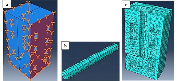
Then, from (Edit boundary conditions tab), the boundary conditions for both die blocks and the specimen are defined. For die blocks, the boundary conditions are defined to be Symmetry/Anti-symmetry/ Encastre with CSYS of encastre (U1=U2=U3=URI=UR2=UR3=0) while, for specimen, the boundary conditions are defined to be Velocity/Angular velocity with (pressing speed=V2) of 20mm/ sec. Figure 1a shows the assembly of ECAP die after applying the boundary conditions.
G. Defining mesh module.
In this module, a suitable mesh size is applied to die blocks and the specimen, as shown in Figure 1b, c. Mesh size should not be too large in order to obtain accurate results and also not to be very small to avoid large processing time of the program during analysis.
Figure 1:Geometrical representation of ECAP die on Abaqus program:
(a) Die assembly after applying the boundary conditions,
(b) Specimen and
(c) Die block after meshing.
H. Defining Job module.
From job module, the created job is submitted for analysis. From (Monitor Tab), the results can be monitored during processing.
I. Visualization module.
In this module, the stress analysis results of the die blocks are appeared. In order to present the Abaqus analysis of specimen, a rigid body constrain is entered to the die block, then visualization of the specimen is opened. Commercially pure 1100 Al alloy is selected for ECAP processing with Bc route of deformation.
Die manufacturing procedure
According the Abaqus analysis results, the optimum ECAP die dimensions were determined. The manufacturing procedure of the ECAP die included: at first, the channel was machined (slotting) using CNC into the die block, then twelve holes for fixtures were CNC drilled. Finally, the block was cut into two identical blocks.
Materials Processing
As-received material
Commercially pure as-cast 1100 Al specimens with 14.8mm diameter and 120mm length were used to be processed by ECAP. A clearance of 0.2mm, between the die channel and specimen diameters, is applied. The chemical composition (wt.%) of the 1100 Al alloy is given in Table 3. Commercially pure 1100 Al alloy is available and has a wide range of applications, such as: spun hollowware, fin stock, heat exchanger fins, rivets, reflectors, and in sheet metal work.
Table 3:Chemical composition of the as-received 1100 commercially pure Al.

ECAP processing
Three passes of ECAP were undertaken on 1100 Al specimens using Bc route, i.e. rotated by 90° after each pass in the same directions, in order to ensure a uniform and accumulative strain, at room temperature. During the ECAP processing, a suitable lubrication is essential to reduce the frictional influences, tool wear and the loads necessary for plastic deformation [5]. Molybdenum disulphide (MoS2) was used as a lubricant. MoS2 lubricant is characterized by low friction coefficient of μ=0.09 and no stick-slip. Prior to ECAP processing, the die channel and specimen were lubricated in order to reduce the friction during operation. The experiments were conducted using a hydraulic manual press of 250 tons capacity, every handle stroke is equal to 3mm punch stroke and achieved after 3sec. The total stroke for one pass is 120mm, equals to the specimen length.
Mechanical characterization
Tensile specimens with 6mm diameter and 30mm gauge length were machined form rods after each ECAP pass. Tensile test was conducted according to ASTM E8 using 20KN universal tensile testing machine. The average of two tensile specimen results were recorded.
Result and Discussion
Stress analysis, die design optimization and manufacturing
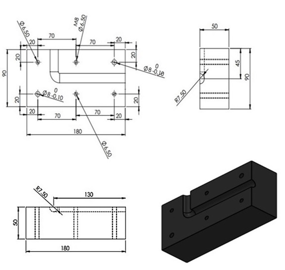
The results of stress analysis of the ECAP die during processing, using von Mises criterion in Abaqus program is shown in Figure 2. According to Abaqus analysis, the maximum stress induced to the die due to the specimen deformation is about 242.9MPa. This value is very lower than the yield strength of the die materials (Table 2). Therefore, the results reveal safe design where there is no die fracture due to the generated residual stress during ECAP processing. Figure 3 presents the optimum ECAP die dimensions according to the results of Abaqus analysis. The outer dimensions of the one die block are 180x90x50mm with the inlet and outlet channels have 120mm and 45mm length, respectively. This design represents the optimum die design from cost point of view, i.e. it is the smallest dimensions that can be used to obtain safe die; hence save material and cost.
Figure 2:Stress analysis of the ECAP die during processing using von Mises criterion in Abaqus program.
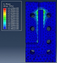
Figure 3:Optimum ECAP die dimensions according to the results of Abaqus analysis.
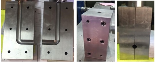
The next step for attaining the optimum die design is the manufacturing. Figure 4 presents a schematic representation of the ECAP die manufacturing procedure. The manufacturing involves three steps. At first, one block of dimensions 180x180x50 mm is slotted using CNC machine to produce the inner half-channel with dimensions of 15mm diameterx130mm lengthx45mm width (Figure 4a). Then, twelve holes are CNC drilled (Figure 4b). Finally, the block is cut into two equal blocks (Figure 4c). Figure 5 shows the ECAP die after manufacturing from different profiles.
Figure 4:A schematic representation of ECAP die manufacturing procedure:
(a) CNC slotting,
(b) CNC drilling and
(c) cutting into two equal blocks.
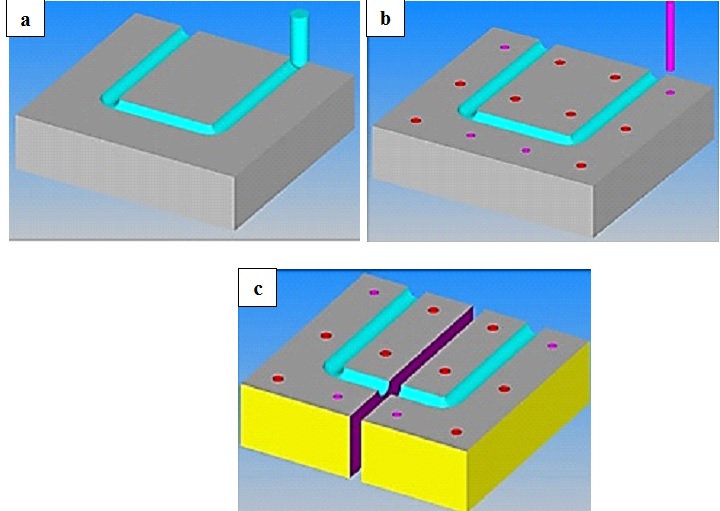
Figure 5:ECAP die after manufacturing from different profiles.
ECAP processing handicaps
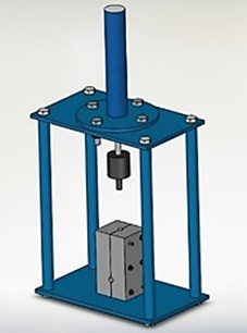
Figure 6 shows a schematic representation of the ECAP die and the press setup. Although well studying of the ECAP processing procedure and taking all regards in considerations, some handicaps are appeared during processing. At first, although the die closing system (fixation of the die) was studied during Abaqus analysis to include four screws and two pads. This fixation system was failed and instead a steel sickle had been used.
Figure 6:A schematic representation of the ECAP die and the press setup.
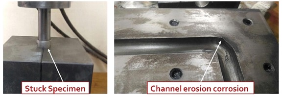
Other handicap involves the stuck of specimen inside the channel was appeared during processing. This problem is a result of poor lubrication which also results in erosion in the die channel, as shown in Figure 7. Therefore, selection of a suitable lubricant with low friction coefficient, coating the inner channel of the die before processing and immersion of the specimen in the lubricant are not enough lubrication procedure. Disassembling the die after each pass, coating the inner channel with lubricant and reinstallation is compulsory. Certainly, these proceedings are time consuming.
In addition, utilizing a manual press during ECAP processing is not recommended. As specimen becomes harder after each ECAP pass, so the required press pressure increases, as presented in Table 4. As, number of ECAP passes increases, reaching the required pressure manually through moving the piston’s handle becomes very difficult.
Table 4:Piston pressure required for each ECAP pass.

Figure 7:Results of poor lubrication
Effect of ECAP on tensile properties
The value of equivalent shear strain imposed in ECAP is determined by an equation reported previously [7]. This value depends on the die angle (Φ), and the angle of the outer arc of curvature, where the two the channels intersect (Ψ). In this work, the ECAP induces equivalent strain of one per each ECAP pass.
The influence of ECAP die geometry and number of ECAP passes on irregularity of shear stress field in the cross section of the specimen, using von Mises criterion in Abaqus program, is shown in Figure 8. As the number of ECAP passes increases, the values of the induced shear stress increase with irregular distribution. It is reported that depending on die geometry and friction condition that irregularity could be reduced [8]. According to the Abaqus analysis, the maximum induced stress in the first ECAP pass was 138.3MPa while the maximum induced stress in the second and third ECAP pass was 152.2MPa
Figure 8:Stress analysis of the specimen during ECAP processing using von Mises criterion in Abaqus program.

Figure 9:Stress-strain curves before and after ECAP of pure 1100 Al.
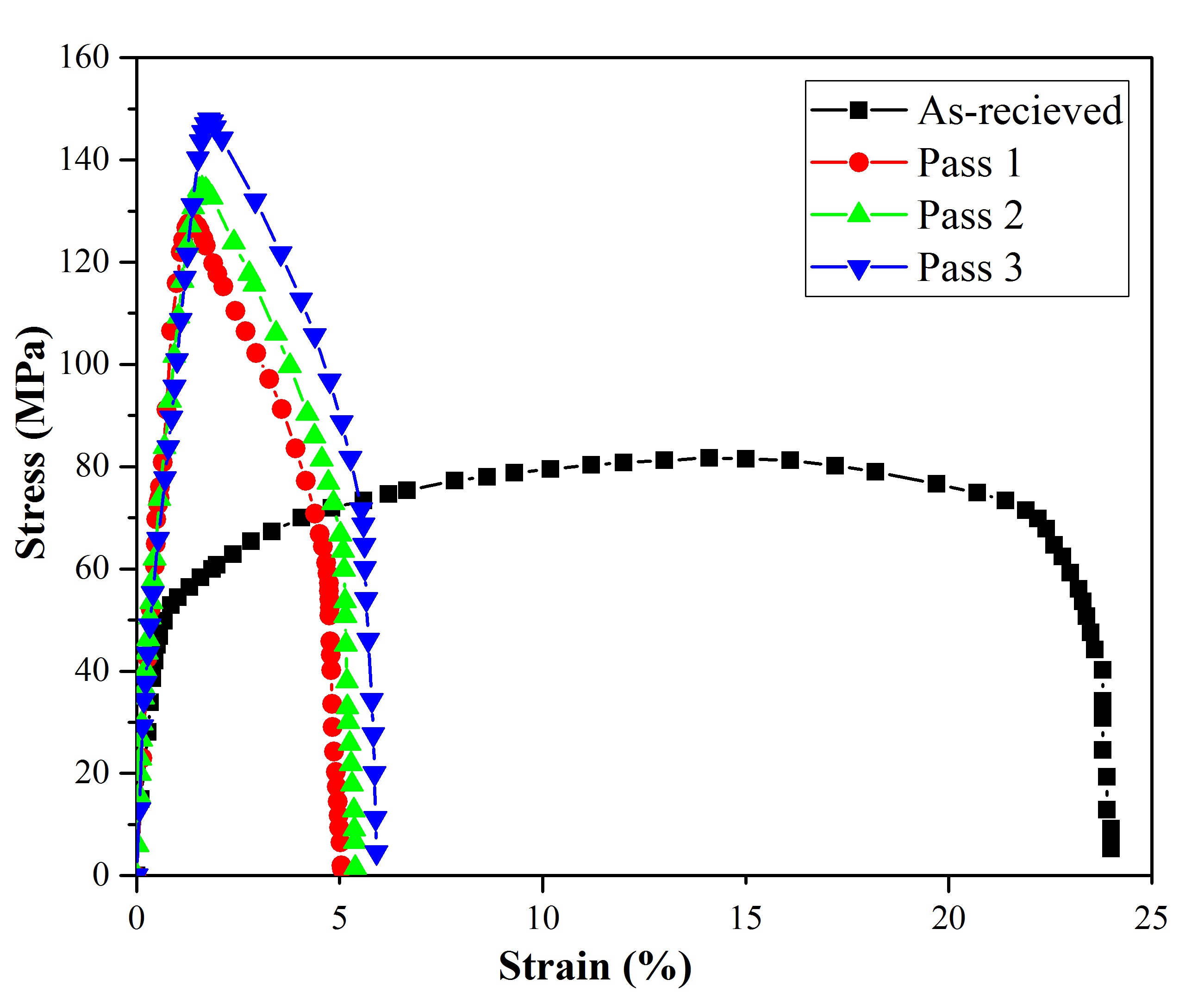
Figure 10:Effect of number of ECAP passes on tensile properties of pure 1100Al.
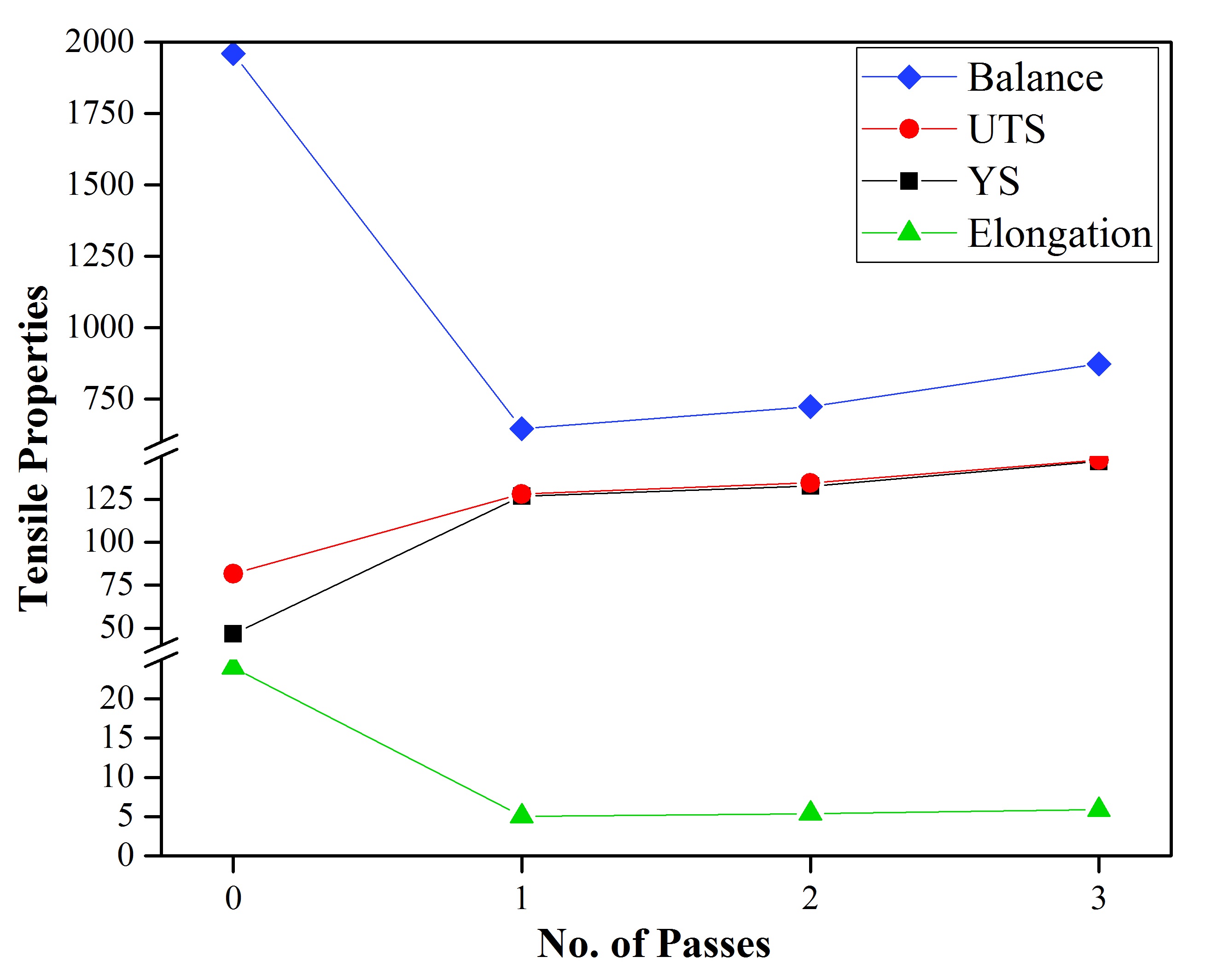
Figure 9 presents the stress-strain curves before and after ECAP of pure 1100 Al. Figure 10 shows the effect of number of ECAP passes on the tensile properties. As the number of ECAP passes increases, both ultimate and yield tensile strength increase. A shown from Figure 10, the first ECAP pass results in significant increase of the ultimate and yield tensile strength by 56.73% and 170.78%, respectively, as compared with the as-received material. While increasing number of ECAP passes, from first to third pass, improve the ultimate and yield tensile strength by 15.47% and 15.95, respectively.
After the first ECAP pass, the total elongation decreases by 78.94% as compared to the as-received materials. This result is in agreement with previous results [4,9]. Increasing number of ECAP passes improves the total elongation by 6.61% and 16.86% after the second and third pass, respectively, as compared to the first ECAP pass. In previous work studied the effect of ECAP on 1100 Al [4,9], sight change in the elongation was occurred during ECAP passes.
Strength-ductility balance is obtained from multiplying ultimate tensile strength and total elongation. Strength-ductility balance decreases after first ECAP pass by 66.99%, as compared to as received materials. As shown in Figure 10, strength-ductility balance is promoted by ECAP process by 11.97% and 34.93% after the second and third pass, respectively, as compared to the first ECAP pass. According to these results, the best combination between strength and ductility for pure 1100 Al is occurred after the third ECAP pass.
Conclusions
ECAP is one of SPD processing technique that promotes the mechanical properties of metallic materials. In the current work, ECAP technique was adopted beginning from ECAP die design to material processing and characterizations. The designing, Abaqus stress analysis and manufacturing procedure of the ECAP die were described. In addition, commercially pure 1100 Al alloy specimens were experimentally processed using ECAP method through a twopiece split-type die consisting of two channels of equal cross sections, intersecting at an angle of 90° using Bc route at room temperature. The total equivalent strain is three after the third ECAP pass. The handicaps of ECAP processing were mentioned. Mechanical characterization using tensile test was carried out.
The following conclusions can be drawn:
A. FEM using Abaqus program is an excellent tool to reach safe and optimum ECAP die design. A two-piece split-type ECAP die with minimum allowable dimensions that saves the material cost is attained.
B. During ECAP processing, die fixation system should be accurately studied and tested before processing, lubrication should be applied after each ECAP pass to the die and specimen and finally using of manual press should be avoided.
C. As the number of ECAP passes increases, the tensile properties improve. Ultimate tensile strength, elongation and strength-ductility balance increase by 15.47%, 16.86% and 34.93% after third pass as compared to the first pass.
References
- Figueiredo R, Langdon T (2009) Using severe plastic deformation for the processing of advanced engineering materials. Materials Transactions 50(7): 1613-1619.
- Kumar S, Ravisankar B, Sathya P, Thomas PV, Vijayalakshmi M (2014) Equal channel angular pressing of an aluminum magnesium alloy at room temperature. Transactions of the Indian Institute of Metals 67(4): 477-484.
- Filho A, Prados E, Valio G, Robert J, Sordi V, et al. (2011) Severe plastic deformation by equal channel angular pressing: Product quality and operational details. Materials Research 14(3): 335-339.
- Mufadi FA, Djavanroodi F (2014) Finite element modeling and mechanical properties of aluminum proceed by equal channel angular pressing process, world academy of science. Engineering and Technology International Journal of Materials and Metallurgical Engineering 8(8): 1436- 1441.
- Sanusi K, Makinde O, Oliver G, (2012) Equal channel angular pressing technique for the formation of ultra-fine-grained structures. South African Journal of Science 108(9-10): 1-7.
- Abd El Aal M, El Mahallawy N, Shehata F, Abd El Hameed Mo, Yoon E, et al. (2010) Tensile properties and fracture characteristics of ECAP-processed AL and Al-Cu alloys. Metals and Materials International 16(5): 709-716.
- Valiev R, Estrin Y, Horita Z, Langdon T, Zehetbauer M et al. (2006) Producing bulk ultrafine-grained materials by severe plastic deformation. JOM 58(4): 33-39.
- Parshikov R, Rudskoy A, Zolotov A, Tolochko O (2013) Technological problems of equal channel angular pressing. Rev Adv Mater Sci 34: 26- 36.
- Horita Z, Fujinami T, Nemoto M, Langdon T (2000) Equal-channel angular pressing of commercial aluminum alloys: Grain refinement, thermal stability and tensile properties. Metallurgical and Materials Transactions A 31(3): 691-701.
© 2019 Reham Reda. This is an open access article distributed under the terms of the Creative Commons Attribution License , which permits unrestricted use, distribution, and build upon your work non-commercially.
 a Creative Commons Attribution 4.0 International License. Based on a work at www.crimsonpublishers.com.
Best viewed in


.jpg)


 Editorial Board Registrations
 Submit your Article
 Refer a Friend
 Advertise With Us
.jpg)


.jpg)


.bmp)
.jpg)
.png)
.jpg)


.jpg)


.png)

.png)


.png)


