
- About Us
- Information
-

The Author ensures that the research has been conducted responsibly and ethically with adherence to all relevant regulations. read more..
- For Authors
- For Reviewer
- Manuscript Guidelines
- Membership
- Publication Ethics
-
- Journals
- Reprints
- e-Books
- Videos
- Policies
- Contact Us
 COVID-19
- Submissions


Full Text
Evolutions in Mechanical Engineering
Numerical Modeling of Nano Bundle and Nano Rope-Reinforced Polymer Mechanical Properties
Seyed Hossein Mamanpush1*, Zohre Matin Ghahfarokhi2 and Hossein Golestanian2,3
1 Composite Materials and Engineering Center, Washington State University, USA
2 Faculty of Engineering, University of Shahrekord, Iran
3 Nanotechnology Research Center, University of Shahrekord, Iran
*Corresponding author:Seyed Hossein Mamanpush, Composite Materials and Engineering Center, Washington State University, Pullman, WA, 99163, USA
Submission: July 07, 2018;Published: October 22, 2018

ISSN 2640-9690 Volume1 Issue4
Abstract
Carbon nanotubes (CNTs) demonstrate unusually high stiffness, strength and resilience, and are ideal reinforcing materials for polymer-based nanocomposites. Van der Waals interactions between the nanotubes often result in formation of nanotube bundles and/or ropes. Determination of mechanical properties of the nano bundle and nano rope-based nanocomposites is difficult due to the complicated geometries of the reinforcement structures. However, to better utilize nanocomposites, it is crucial to determine mechanical properties of nanocomposites in their real form as much as possible. In this paper, the elasticity theory for anisotropic body and continuum modeling are used to determine effective mechanical properties of bundle and nanorope-based nanocomposites. Numerical models are developed using a Representative Volume Element (RVE) consisting of nanoropes and nanobundles made up of different numbers of nanotubes to investigate the effect of nanorope geometry on nanocomposite mechanical properties. Models of several RVEs are developed with nanoropes consisting of five, seven, nine, and thirteen CNTs. CNT volume fraction is kept constant in all models for a valid comparison. Also, the effect of matrix modulus on the strengthening efficiency of CNTs is investigated. The results indicate that nanocomposite longitudinal modulus decreases with increasing the number of CNTs in the nanorope.
Keywords: Nanorope; Nanobundles; Anisotropy; Nanocomposite; Mechanical properties
Introduction
The discovery of single-walled carbon nanotubes (SWCNTs) resulted in the potential for the development of high-performance composite materials. The extraordinary mechanical and physical properties of CNTs such as: small size, low density, high stiffness, high strength, and high aspect ratio have made these materials excellent candidates for a wide range of applications [1,2]. There have been varying reports on mechanical properties of CNTs. Theoretical and experimental results have suggested elastic modulus in the range of 1TPa and strengths between 13 to 52GPa for SWCNTs [3-7]. These high modulus and strength properties of carbon nanotubes offer a prominent mechanism to enhance both strength and stiffness characteristics of polymer matrix composites [8-10]. Especially, it has been addressed that CNTs’ outstanding Young’s modulus and tensile strength make them one of the most promising reinforcements in nanocomposite manufacturing [11- 13]. However, uniform dispersion, the waviness, matrix modulus, and CNT/matrix interface bonding condition are among the important factors influencing nanocomposite effective [14]. For effective reinforcement, the nanotubes must be uniformly dispersed within the matrix. However, Van der Waals interactions between the nanotubes often result in formation of nanotube ropes inside the matrix [15].
The computational approaches used to determine nanocomposite mechanical properties can be divided into molecular dynamics (MD) and continuum mechanics-based methods. The MD has yielded many simulation results to understand the behavior of individual and bundle CNTs not implemented in a matrix material. However, the MD is still limited to very small length and time scales, simulation of a system containing 106-108 atoms for the period of a few nanoseconds. Therefore, continuum mechanics method is currently used for the simulation of larger systems [16]. existing work shows that the results obtained from continuum mechanics approach are close to those obtained from MD simulations for single and double walled nanotubes [17]. Fisher et al. [18,19] assumed that the nanotube would follow a cosine function in a 2D domain. They considered a single nanotube subjected to normal, shear and bending deformations and analytically evaluated the strain energy utilizing Castligiano’s theorem. Pipes and Hubert used the elastic constants of nanotube bundles to predict twisted nanotube yarn mechanical properties [20]. Mylvaganam et al. [21] used the molecular dynamic analysis and continuum mechanics characterization to investigate the deformation mechanism of a SWCNT in pure bending. They showed that at a bending angle of 24 degrees the nanotube buckles locally, forming a kink in the middle. As the bend- ing angle increases, the kink progresses along the nanotube and its shape changes in both longitudinal and circumferential directions.
In many cases SWCNT bundles naturally assume a twisted form, which is similar to the wire ropes at a continuum scale [22]. It is well known from continuum mechanics analysis of other types of wire or fiber forms that twisting the wires or “weaving” the fibers can lead to a cable or rope that has a much better load transfer mechanism in tension than a straight bundle [23]. Ren et al. [24] used molecular mechanics simulation and tensile loading to investigate fatigue failure mechanism of SWCNT bundles embedded in a polymeric matrix. They found that SWCNTs within the rope do not break at the same time or at the same location. Vodenitcharova investigated the inter-tubular van der Waals interactions that produce the initial cross-sectional distortion of single-walled carbon nanotubes during a bundle formation [25]. These investigators determined the distributions of the van der Waals force by combining the analysis of molecular dynamics with continuum mechanics. Walters et al. [26]. obtained yield strength of 45±7 GPa for nanotube ropes. Pipes & Hubert [20,27] used textile mechanics and elasticity methods to evaluate the effective elastic properties of twisted carbon nanotube arrays. The study by Qian et al. [28] showed that twisting could significantly decrease the required contact length for a complete load transfer between nanorope and matrix. Ashrafi & Hubert [29] used finite element analysis and strain energy approaches to investigate the elastic properties of SWCNT arrays and their composites [29]. They predicted properties of twisted SWCNT nano-arrays. These investigators studied the effect of nano-array volume fraction and aspect ratio for dilute polymer composite systems using conventional micromechanics. Their results indicated that the axial Young’s modulus of a nanotube array decreases dramatically even for small twist angles.
As stated above, nanotubes seldom exist as straight and individual in the matrix and usually form bundles or ropes consisting of several CNTs twisted together. Figure 1 shows an SEM image of a nanorope inside a matrix in which the roping/ twisting of the nanotube is obvious. As can be seen from the presented literature review, much research has been performed on dispersed (individual) nanotube-reinforced nanocomposites. Few researchers have addressed the bundling and roping effect of CNTs on nanocomposite mechanical properties. In this research, the elasticity theories for anisotropic bodies are used to evaluate effective mechanical properties of nanobundle and nanorope-reinforced polymers. To achieve our goals, several models are developed and analyzed in ABAQUS finite element software. Representative Volume Elements (RVE) reinforced with nanobundle and nanoropes consisting of different numbers of SWCNTs are modeled to investigate the influence of reinforcement characteristics on nanocomposite effective mechanical properties. The effect of matrix modulus on the strengthening efficiency of CNTs is also investigated. The analysis and results of this investigation are presented in the following sections.
Figure 1:SEM image of a carbon nanorope [13].

Analysis of the RVE Reinforced with Nanobundle
Figure 2:The RVE used to simulate the CNT bundle-reinforced polymer

To derive the relations for extracting nanocomposite equivalent material constants, a homogenized elasticity model of the square RVE is considered as shown in Figure 2. The CNTs in the bundle are straight and parallel to each other and are oriented in the z-direction along the RVE. The RVE is 266nm long with a square cross section of 43.28 nm in length on each side. The CNTs are 236 nm long and 5.44 nm in diameter. The nanobundle is placed in the middle of the RVE. Nanotube volume fraction in the RVE is kept constant at 7.7% in all models for a better comparison of the results. The directions of the coordinate axes are also shown in this figure. Elasticity solutions can be obtained under certain load cases. The elasticity model has five independent material constants (ex= ey, ez, Gxy, υxy, and υzx). In this paper, nanocomposite Young’s moduli are determined. The general 3-D strain-stress relation relating the normal stresses and strains for a transversely isotropic material can be written as [30].
Equation (1) is the generalized Hook’s law for an orthotropic body. To determine ex, ez, we also need to determine Poisson’s ratios υxy, υzx as will be shown in follow Section. Thus, four equations will be needed in this case [30]. Two loading cases have been devised to provide four such equations based on the elasticity theory, as explained in the following sections..
Square RVE under an axial elongation ΔL
In this case, shown in Figure 3a, let L denote the length of simulated RVE in the z-direction and the cross-sectional dimension be denoted by letter a. An elongation ΔL is imposed on the RVE in the z-direction. Due to Poisson’s ratio effect, changes of cross sectional dimensions equal to Δx and Δy are created in the x- and y-directions, respectively.
Stress and strain components on the lateral surface are as follows [30]
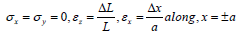
Integrating and averaging the third equation in (1) on the plane z = L/2, we obtain
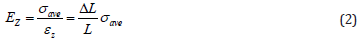
Where ơave is the averaged value of stress in the z-direction, given by

In equation (3), A is the RVE cross sectional area. The value of σave is evaluated by averaging stress in the z-direction on the plane z = L/2 in the FEA model. Using the first relation in equation (1), and the relation between stress and strain, along x = ±a, we have
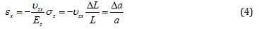
Thus, we can obtain an expression for the Poisson’s ratio as follows
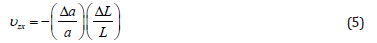
Equations (2) and (5) can be applied to estimate the effective Young’s modulus ez and Poisson’s ratio υzx (= υzy), once the contraction Δa and the average stress, ơave, in case (a) are obtained from FEA results.
Square RVE under a lateral uniform load
In this load case, shown in Figure 3b, the RVE is placed under a lateral uniform load, p, in the y-direction. The RVE is constrained in the z-direction so that the plane strain condition is maintained in order to simulate the interactions between the nanotube and matrix materials existing in the z-direction. Thus, since ez=0 for plane strain case, equation (1) reduces to
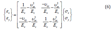
Figure 3:(a) RVE under axial distributed load p. and (b) RVE under lateral distributed load p.

In this load case, the values of stress and strain components at a point on the lateral surfaces are given by
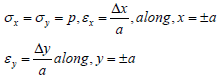
Appling the first and second equations in (6) for points along x=±a and y=±a, together with the above conditions, we obtain
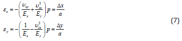
Solving these two equations gives the effective Young’s modulus and Poisson’s ratio in the transverse direction as follows
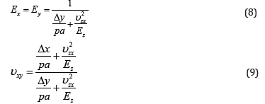
The results of axial elongation loading case are used in equations (8) and (9) for ez and υzx. Once the changes in dimensions, Δx and Δy, are determined for the square RVE from a finite element analysis, ex=ey and υxy can be computed from equations (8) and (9), respectively [30].
Analysis of the RVE reinforced with nanorope
In this section, the models used to determine effective mechanical properties of nanorope-based nanocomposites are presented. Four RVEs, reinforced with nanoropes consisting of five, seven, nine, and thirteen nanotubes are modeled. CNT volume fraction in the RVEs is kept at 7.7% in all cases. Figure 4 shows the RVE used to model the nanorope-based nanocomposite in this investigation. The RVE consists of a nanorope and the surrounding matrix. Several assumptions are made in the analysis. First, the nanorope is perfectly bonded to the matrix. Second, the individual SWCNTs in the nanorope have uniform diameters and equal lengths. Third, there is no direct interaction between the adjacent CNTs in the nanorope. And finally, the matrix and the constituent nanotubes in the nanorope are homogeneous materials.
Approach
In this section, the approach used to extract relations for evaluating the effective material constants of the square RVEs are established based on elasticity theory for anisotropic bodies. The generalized Hooke’s law based on the elasticity theory for anisotropic body is given by equation (10) [31].
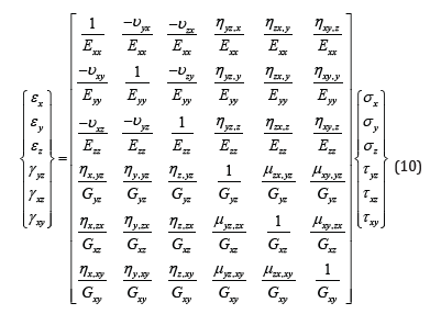
In equation (10), ex, ey, and ez are Young’s moduli in directions x, y, and z. Gxy, Gxz, and Gyz are the shear moduli for planes parallel to the coordinate planes. In addition υij are Poisson’s ratios characterizing the strain in jth direction due to the applied stress in ith direction.
The coefficients μzx,yz,…, μzx,xy characterize shears in planes parallel to the coordinate planes produced by shearing stresses acting in other planes parallel to the coordinate planes. These coefficients are called Choentsov’s coefficients.
The constants ηyz,x, …, ηxy,z characterize extension in the directions of the coordinate axes produced by shearing stresses acting in the coordinate planes. The ey are termed the mutual influence coefficients of the first kind. Finally, ηx,yz, …, ηz,xy, are called the mutual influence coefficients of the second kind. These coefficients express shears in the coordinate planes due to normal stresses acting in the directions of the coordinate axes [31]. These constants are usually non-zero for an anisotropic elastic body and are zero for an isotropic body. Since the nanorope is an anisotropic body, the RVE containing the nanorope is also anisotropic. In the general case of anisotropy each strain component is a linear function of all six stress components. Then, the RVE has nine independent material constants. In order to determine these constants, nine independent equations are needed. These equations are obtained by loading the RVE in the x-, y-, and z-directions by arbitrary distributed stresses separately and using the first three relationships in equation (10). Using this approach, we can obtain the nine needed equations to determine the nanocomposite effective mechanical properties. Equation (10) reduces to equation (1) for this case since no shearing stresses are applied to the RVE [32].
Initially, the RVE shown in Figure 4 is loaded by a tensile stress along the x-axis. Then, using the first relation in equation (1), Young’s modulus ex can be calculated. Using a similar method for loadings in the y- and z-directions and using the second and the third relations in equation (1), Young’s moduli ey and ez, are determined. In equation (1), strain components in different directions are calculated using
Figure 4:The RVE used to model the polymer nanocomposite reinforced with nanorope.


Where, u is the average value of displacement of nodes on the considered plane and L is the initial length of the RVE in the corresponding direction. The strains needed in equations are extracted from the FEM results. The FEA models and analysis results are described in the following sections.
Continuum modeling
Four nanocomposites reinforced with nanoropes consisting of five, seven, nine, and thirteen SWCNTs were modeled. These models were analyzed to investigate the effects of nanorope characteristics on nanocomposite effective mechanical properties. Simulated nanorope and its cross section are shown in Figure 5 for the nanorope consisting of seven SWCNTs. In this nanorope, a straight SWCNT is placed at the center of the nanorope and six helical SWCNTs surround the central SWCNT. The other three nanoropes are similar in shape and one straight CNT is in the middle surrounded by the other helical CNTs. The dimensions of the RVE are 43.28×43.28×266nm and the length of the nanorope inside the RVE is 236nm. Diameter of each nanotube in the nanoropes is 5.44nm and helical angle of the surrounding nanotubes in the nanoropes is 16 degrees. Material properties of the constituents are taken from references and are listed in Table 1 [32,33]. As mentioned above, three different loadings were applied to the RVE to obtain the required equations.
Table 1:Mechanical properties of nanocomposite constituents.

Figure 5:(a) The nanorope used as the reinforcement in the matrix, and (b) cross-section of the nanorope consisting of seven SWCNTs.

In each case, the RVE is fixed at one end in one of the coordinate directions and a distributed load is applied at the other end in the corresponding direction. As an example, a model is created in which the RVE is fixed in the x-direction in one end and a distributed load is applied at the other end of the RVE in the same, x, direction. The same is done in the y- and z-directions. The nanocomposite mechanical properties are then determined following the procedures presented in the previous section.
Results and Discussion
Figure 6:Von Mises stress contour plot for the RVE under an arbitrary distributed load in the z-direction.

Models were developed based on the above discussions to determine nanocomposite effective mechanical properties. The results of the FEA models are presented in this section. As mentioned above, six different models were created and analyzed as two sets of different models. The first set of models consisted of two nanocomposites reinforced with nanobundles made up of seven and nine CNTs. The second set of models consisted of four nanocomposites reinforced with nanoropes made up of five, seven, nine, and thirteen CNTs. The CNT volume fraction in the RVE is 7.7% in all models. Also, matrix modulus was varied from 3.2 to 100 GPa to investigate the effects of matrix modulus on strengthening efficiency of nanoropes. Before presenting the results, some observations made on the stress variations in the RVE under the applied loads are discussed. Von Mises stress contour plot in the RVE under the arbitrary stress σz is shown in Figure 6.
Figure 7:Von Mises stress contour plot of the nanorope inside the RVE under an arbitrary distributed load in the z-direction.

Figure 7 presents the stress variation in the nanorope consisting of seven nanotubes under the same loading condition. The matrix material surrounding the nanorope has been removed to better present the stress build-up in the nanorope. Note that the maximum stresses occur in the nanorope. This suggests that the nanorope is taking most of the load applied to the RVE. Also observe that the stresses in the straight core CNT is even higher than those in the helical CNTs surrounding the core nanotube. This suggests that the core CNT takes even more load than the helical CNTs. The reason is that the core CNT is aligned in the loading direction, whereas the helical CNTs surrounding the core twist outward as they wrap around the core CNT.
Figure 8:Variation of E z/Em with matrix modulus for the six nanocomposites.

Figure 9:Variation of ex/Em= ey/Em with matrix modulus for the six nanocomposites.

The nanocomposite moduli determined from FEA models are presented in Figure 8 & 9. Figure 8 presents the variation of the ratio of nanocomposite longitudinal modulus to matrix modulus for all six nanocomposites under investigation. Several interesting observations can be made from this figure. First, the longitudinal modulus of the nanocomposite reinforced with the nanobundles is higher than the nanorope-reinforced polymer. This is because in case of nanobundles, the CNTs are straight and are oriented in the z-direction. Also, the longitudinal modulus of the nanocomposite reinforced with the nanobundle consisting of nine CNTs in the bundle is higher than that consisting of seven CNTs. This result indicates that, at equal CNT volume fractions, the number of CNTs making up the bundle influences the reinforcing efficiency of the nanobundle.
Second, the longitudinal modulus of the nanocomposite reinforced with the nanorope consisting of five CNTs is higher than the other three cases. This is because, as the number of CNTs in the nanorope increases, the CNTs are redirected more towards the transverse directions, x and y. Third, the ratio of nanocomposite longitudinal modulus to matrix modulus converges to a value of 1.33 at Em=100GPa. It seems that this is the lower limit of nanorope reinforcing effect. Also, at high matrix moduli the number of CNTs in the nanorope has negligible effect on reinforcing efficiency of the nanorope. Finally, the ratio of nanocomposite modulus to matrix modulus decreases sharply with increasing matrix modulus in all cases for matrix modulus below 40GPa. The curves level off as matrix modulus increases above 80GPa. These results suggest that both nanobundles and nanoropes are much more efficient in reinforcing matrices with lower moduli of elasticity.
Variation of the ratio of nanocomposite transverse modulus to matrix modulus is shown in Figure 9. Note that the nanocomposite transverse modulus is much lower than the longitudinal modulus for all six nanocomposites. Also, note that nanoropes strengthen the nanocomposite in the transverse direction as well as in the longitudinal direction. This is different from the case of nanocomposites reinforced with purely straight CNTs [32]. The reason for this strengthening is that some parts of the surrounding CNTs are directed along the x- and y-directions as they twist around the core CNT. In addition, the nanorope consisting of thirteen CNTs is more efficient in strengthening the nanocomposite in the transverse direction. This trend is opposite to that obtained for the longitudinal modulus variations. This opposite trend verifies the reasoning given for the lower longitudinal modulus of nanocomposite reinforced with the nanorope consisting of thirteen nanotubes compared to the other three cases. Finally, unlike the longitudinal modulus case, nanocomposite transverse modulus depends strongly on the number of CNTs in the nanorope at high matrix moduli. That is, the strengthening effect decreases slightly with matrix modulus in this case.
Observations on the transverse modulus of nanobundlereinforced polymer suggest a different trend. Note that the ratio of nanocomposite transverse modulus to matrix modulus increases from about 0.73 to almost 0.94 as the matrix modulus increases from 3.2 to 100GPa. This trend is opposite to that observed for the longitudinal modulus case even though the change is much less pronounced. These results suggest that the presence of individual parallel CNTs, making the bundle, in fact weakens the matrix in the transverse direction. This is since the CNTs produce discontinuities in the matrix and act as cavities in the transverse direction.
Verification of the results
In this section, the results of the current investigation are compared with those found in the literature. An exact comparison of all results to those found in the literature is difficult due to the various parameters involved. Therefore, we tried to find the closest cases in the literature for a reasonable comparison. This comparison is presented in Table 2. The results of our models on nanocomposite reinforced with the nanobundles are compared with the results presented by Ashrafi and Hubert et al. [29] These investigators determined variation of longitudinal Young’s modulus of a SWNT array/LaRC-SI composite for aligned SWNT array versus CNT volume fraction for twist angles of 0º and 10º. They considered CNTs with aspect ratios of 12 and 600. In our models, the CNT aspect ratio is 44 and angle of twist is 16º. As can be observed, the model parameters are somewhat different in the two cases. Therefore, interpolation on their results was performed for a better comparison. That is, the closest value was obtained from their graphs and the results were compared with our FEA results. This comparison is presented in Table 2. Note that the difference between the reference results with ours is almost 7% and 16% for the bundles with nine and seven nanotubes, respectively. Thus, the results of our models are in good agreement with those found in the literature. The main reason for this small difference is believed to be due to the difference in the model parameters.
Table 2:Comparison of the results obtained in this investigation with those found in the literature for the straight CNT reinforced nanocomposite.

Concluding Remarks
In this paper, the elasticity theory for the anisotropic body and FEA simulations were used to determine mechanical properties of nanobundle and nanorope-reinforced nanocomposites. Models consisting of nanoropes and nanobundles made up of different numbers of CNTs were analyzed. FEA results suggest that the maximum stress occurs in the CNTs indicating that the nanotubes in the nanorope and nanobundle take most of the applied load on the nanocomposite. Nanocomposite longitudinal modulus decreases with increasing the number of CNTs in the nanorope. This is due to the larger curvature of the CNTs making up nanoropes with higher number of CNTs. In addition, the ratio of nanocomposite longitudinal modulus to matrix modulus converges to a value of 1.33 at Em=100GPa for all nanorope-reinforced polymers. It seems that this is the lower limit of nanorope reinforcing effect. This result indicates that, at high matrix moduli the number of CNTs in the nanorope has a negligible effect on reinforcing efficiency of the nanorope. The ratio of nanocomposite transverse moduli to matrix modulus of the nanorope-reinforced polymer turned out to be higher than unity. The CNT curvature in the nanorope is responsible for this transverse strengthening.
The nanobundle-reinforced polymer longitudinal modulus was higher for the bundle with higher number of CNTs. The ratio of nanocomposite transverse moduli to matrix modulus was lower than unity for the nanobundle-reinforced polymer. In fact, the presence of nanobundle had a weakening effect on the matrix modulus in the transverse direction. Finally, the ratio of nanocomposite longitudinal modulus to matrix modulus decreased with increasing matrix modulus in all cases. This suggests that nanoropes and nanobundles are more efficient in reinforcing matrices with lower moduli. The results of our models on nanocomposite reinforced with the nanobundles were compared with the results presented in the literature and good agreement was observed.
References
- Pantano A, Modica G, Cappello F (2008) Multiwalled carbon nanotube reinforced polymer composites. Mat Sci Eng A 486(1-2): 222-227.
- Mamanpush H, Golestanian H (2014) Investigating the effects of carbon nanotube orientation on the macroscopic stiffness of nanocomposites. Int J Curr Life Sci 4(4): 1168-1174.
- Yu MF, Files BS, Arepalli S, Ruoff RS (2004) Tensile loading of ropes of single wall carbon nanotubes and their mechanical properties. Phys Rev Lett 84: 5552-5555.
- Mamanpush H, Golestanian H (2014) Evaluation of effective material properties of randomly distributed carbon nanotube composites considering interface effect. Indian J Sci Res 2(1):132-142.
- Lourie O, Wanger HD (1998) Evaluation of Young’s modulus of carbon nanotubes by micro-Raman spectroscopy. J Mat Res 13(9): 2418-2422.
- Mamanpush H, Golestanian H (2014) Effects of carbon nanotube dispersion on the mechanical properties of nanocomposites considering interface effect. International Journal of Current Research 4(8): 4366- 4373.
- Shaabani A, Hooshmand SE, Tabatabaei AT (2016) Synthesis of fully substituted naphthyridines: a novel domino four-component reaction in a deep eutectic solvent system based on choline chloride/urea. Tetrahedron Letters 57(3): 351-353.
- Schadler LS, Giannaris SC, Ajayan PM (1998) Load transfer in carbon nanotube epoxy composites. Appl Phys Lett 73(26): 3842-3844.
- Shaabani A, Afshari R, Hooshmand SE, Tabatabaei AT, Hajishaabanha F (2016) Copper supported on MWCNT-guanidine acetic acid@Fe3O4: synthesis, characterization and application as a novel multi-task nanocatalyst for preparation of triazoles and bis(indolyl)methanes in water. RSC Adv 6(22): 18113-18125.
- Mamanpush SH, Li H, Englund K, Tabatabaei AT (2018) Recycled wind turbine blades as a feedstock for second generation composites. Waste Management 76: 708-714.
- Shaabani S, Tabatabaei AT, Shaabani A Copper(I) oxide nanoparticles supported on magnetic casein as a bio‐supported and magnetically recoverable catalyst for aqueous click chemistry synthesis of 1,4‐ disubstituted 1,2,3‐triazoles. Applied Organometallic Chemistry 31(2): e3559.
- Thostenson ET, Ren Z (2001) Advances in the science and technology of carbon nanotubes and their composites: a review. Comp Sci Tech 61(13); 1899-1912.
- Ahmad S, Azadeh TT, Fatemeh H, Shabnam S, Mozhdeh S, et al. (2017) KMnO4/guanidinium-based sulfonic acid: as an efficient Brønsted acid organocatalyst for the selective oxidation of organic compounds. Journal of Sulfur Chemistry 39(4): 367-379.
- Ahmad S, Azadeh TT, Fatemeh H, Shabnam S (2017) Synthesis, characterization, and catalytic activity of three cobalt-based nanoparticle catalysts supported on guanidineacetic acid-functionalized cellulose, Monatshefte für Chemie-Chemical Monthly 148(12): 2079-2090.
- Thostenson ET, Karandikar PG, Chou TW (2005) Fabrication and characterization of reaction bonded silicon carbide/carbon nanotube composites. J Phys D Appl Phys 38(21): 3962-3965.
- Song YS, Youn JR (2006) Modeling of effective elastic properties for polymer-based carbon nanotube composites. Polymer 47(5): 1741- 1748.
- Wang XY, Wang X (2004) Numerical simulation for bending modulus of carbon nanotubes and some explanations for experiment. Compos B 35: 79-86.
- Fisher F (2002) Nanomechanics and the viscoelastic behavior of carbon nanotube-reinforced polymers. PhD thesis, Northwestern University, USA.
- Fisher FT, Bradshaw RD, Brinson LC (2003) Fiber waviness in nanotubereinforced polymer composites-I: Modulus predictions using effective nanotube properties. Comp Sci Tech 63(11): 1689-1703.
- Pipes RB, Hubert P (2002) Helical carbon nanotube arrays: Mechanical properties. Comp Sci Tech 62(3): 419-428.
- Mylvaganam K, Vodenitcharova T, Zhang LC (2006) The bending-kinking analysis of a single-walled carbon nanotube-a combined molecular dynamics and continuum mechanics technique. J Mat Sci 41: 3341-3347.
- Qian LC, Iijima S (2000) Mat Res Soc Sym Proc 593: 33-38.
- Costello GA (1997) Theory of wire rope Springer, New York, USA.
- Ren Y, Fu YQ, Liao K (2004) Fatigue failure mechanisms of single-walled carbon nanotube ropes embedded in epoxy. Appl Phys Lett 84: 2811- 2813.
- Vodenitcharova T, Mylvaganam K, Zhang LC (2007) Mechanical interaction between single-walled carbon nanotubes during the formation of a bundle. J Mat Sci 42(13): 4935-4941.
- Walters DA, Ericson LM, Casavant MJ, Liu J, Colbert DT, et al. (1999) Elastic strain of freely suspended single-wall carbon nanotube ropes. Appl Phys Lett 74: 3803-3805.
- Pipes RB, Hubert P (2003) Scale effects in carbon nanostructures: Selfsimilar analysis. Nano Lett 3(2): 239-243.
- Qian D, Liu WK, Ruoff RS (2003) Load transfer mechanism in carbon nanotube ropes. Comp Sci Tech 63(11): 1561-1569.
- Ashrafi B, Hubert P (2006) Modeling the elastic properties of carbon nanotube array/polymer composites. Comp Sci Tech 66(3-4): 387-396.
- Chen XL, Liu YJ (2004) Square representative volume elements for evaluating the effective material properties of carbon nanotube-based composites. Comput Mat Sci 29(1): 1-11.
- Lekhnitskii SG (1981) Theory of elasticity of an anisotropic body, English translation, translated from the revised Russian edition, MIR Publishers, Moscow, Russia.
- Ghahfarokhi ZH, Golestanian H (2011) Effects of nanotube helical angle on mechanical properties of carbon nanotube reinforced polymer composites. Comput Mat Sci 50(11): 3171-3177.
- Gojny FH, Wichmann MHG, Fiedler B, Karl S (2005) Influence of different carbon nanotubes on the mechanical properties of epoxy matrix composites-A comparative study. Comp Sci Tech 65(15-16): 2300-2313.
© 2018 Seyed Hossein Mamanpush. This is an open access article distributed under the terms of the Creative Commons Attribution License , which permits unrestricted use, distribution, and build upon your work non-commercially.
Editor In Chief


.jpg)


Signup for Newsletter

Quick Links
 Editorial Board Registrations
 Submit your Article
 Refer a Friend
 Advertise With Us
Our Recent Edition

.jpg)


Top Editors


.jpg)


.bmp)
.jpg)
.png)
.jpg)


.jpg)


.png)

.png)


.png)


Financial Support

Sponsors

Latest e-Books

Latest Video

 a Creative Commons Attribution 4.0 International License. Based on a work at www.crimsonpublishers.com.
Best viewed in
a Creative Commons Attribution 4.0 International License. Based on a work at www.crimsonpublishers.com.
Best viewed in