
- About Us
- Information
-

The Author ensures that the research has been conducted responsibly and ethically with adherence to all relevant regulations. read more..
- For Authors
- For Reviewer
- Manuscript Guidelines
- Membership
- Publication Ethics
-
- Journals
- Reprints
- e-Books
- Videos
- Policies
- Contact Us
 COVID-19
- Submissions


Full Text
Evolutions in Mechanical Engineering
Compression Behavior of Pa-12 Pipes Under Large Displacements
De Almeida LS1, de Oliveira TA1, Maurício MHP2 and d’Almeida JRM1,2*
1 Mechanical Engineering Department,State University of Rio de Janeiro, Brazil
2 Chemical and Materials Engineering Department, Pontifícia Universidade Católica do Rio de Janeiro, Brazil
*Corresponding author:d’Almeida JRM, Mechanical Engineering Department, State University of Rio de Janeiro, Rio de Janeiro, Brazil
Submission: August 09, 2018;Published: August 24, 2018

ISSN 2640-9690 Volume1 Issue3
Abstract
Polyamide (PA) pipes are being increasingly employed in fluid distribution networks. Most of these pipes is used in underground networks, where overloads can cause large deflections. Excessive displacement can lead to product failure and can cause surface cracks and leakage of the fluid being transported. This condition can be maximized if the pipe is aged due to effects of the environment or of the fluid itself. In this work, the effect of aging PA pipe segments by their exposure to hot water is presented and discussed. The deformation characteristics of the material before and after aging are evaluated. The results indicate plasticization of the pipes due to exposure to hot water, and, thus, the loads required to cause a specific degree of compression, characterized by reduction of the pipe’s diameter, are greatly reduced. However, the geometric characteristics under large displacements of the aged pipes segments were similar to the behavior of unaged pipe segments, indicating that practical issues like clearances or connections between the pipes and several necessary fittings would not be affected by the aging process.
Keywords: Polyamide, Aging, Compression test, Pipes, Image analysis
Introduction
Polymers have had a growing use in pipes for both water transport as well as in the oil and gas distribution [1,2]. Pipes made of polymeric materials have several advantages in relation to conventional pipes made of metallic materials-mainly, steel or cast iron-among which one can highlight lower density and higher corrosion resistance [3]. Polymers can, however, present other types of damage, such as the loss of mechanical properties due to exposure to UV radiation [4] and the changes in properties due to effects caused by absorption of fluids [5,6]. Absorption of fluid by a polymeric material may cause both chemical and physical aging [6]. In the first case irreversible chemical reactions occur which permanently alter polymer properties. In physical aging only, diffusion of the fluid into the polymer occurs, occupying its free volume [6,7]. Although at physical aging changing of properties can be reversible, the absorbed fluid can reduce the forces of secondary links between the polymer chains, causing reduction of stiffness, in a phenomenon referred to as plasticization [8].
In underground pipes, the UV radiation effect need not be considered, but the effect of plasticization can be very important, especially when the pipe is under road and rail routes. In this situation, overweight due to traffic along these routes can cause excessive deformation of plasticized pipes and failure or permanent deformation of the pipes can occur. Therefore, this work aims to evaluate the variation of the stiffness of a polyamide pipe (nylon 12) after aging by exposure to water and temperature. The stiffness of pipe’s segments before and after aging was evaluated by standard test, simulating the effect of compression loads. The change in stiffness was also qualitatively assessed by digital image analysis.
Experimental Methods and Material
Pipes of nylon 12 (PA-12) with nominal thickness and outer diameter of, respectively, 11mm and 110mm, used for water or gas transportation, were tested in the as received condition from the pipe’s manufacturer. Ring specimens 25.4mm wide were machined from the tubes and have their lateral surfaces reworked to obtain a smooth lateral surface without any machining defect. Aging was done by immersing the samples in tap water bath with controlled temperature. The aging time was 8 months and the aging temperature was 70±2 °C.
The parallel plate tests, Figure 1, were performed on specimens with and without aging, based on ASTM D 2412-08 standard [9]. The load application velocity was of 12.5±0.5mm/min and load were applied by means of two parallel steel plates. These tests have as main objective to evaluate, by visual inspection, whether or not cracks are developed in the region under maximum tensile stress when the tube is flattened (Figure 1). In addition, the standard [9] specifies the procedures to measure stiffness (PS) and the stiffness factor (SF) of the pipe, as well as loads at specific displacements. These two parameters are defined by the following equations:
figure 1:

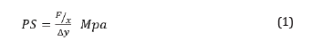
where F/x is the force per unit length of the pipe and Δy is the deflection, and

where r is the mean radius of the pipe, calculated by subtracting from the outer radius half of the wall thickness, as recommended by the above cited standard.
As described in the work of CZEL and CZIGANY [10] it is possible to analyze the deformation process of a pipe through processing and digital image analysis [11]. By using this analysis, geometrical parameters related to the flattened tube can be obtained. These parameters can be related to the overall deformation process [10]. In this work, digital images were captured before and during the test using a digital camera, Sony Cyber-Shot DSC- H1, fixed in front of the pipe segment. It was initially captured the image of the pipe not deformed, which served for the determination of the mm to pixel scale, i.e., the number of pixels of a given length in the image was correlated with a known physical dimension. As shown in Figure 2, the thickness of the tube wall was used to determine the scale.
figure 2:

A sequence of processing steps and digital image analysis was developed in Axiovison 4.8 software (Carl Zeiss) and applied to the digital images of the deformed pipes at the end of each test. This sequence consisted of segmentation, post-processing and measurement steps [12]. In the segmentation step the image was binarized by a manual selection of color shades (yellow) separating the object of interest (the pipe) from the rest of the image (the background), as shown in Figure 3a & 3b. In Figure 3b the image still contains undesired objects, which have similar color tones to the ring, and remain after segmentation of the image. In the post processing step spurious objects are removed by size, since they are much smaller than the pipe ring. A post-processed final image is shown in Figure 3c. Details on these steps of digital image analysis are described in other works [12,13].
figure 3: 3a : Original image of the specimen under test.
3b: segmented or binarized image.
3c: post-processed image, from which the spurious objects were removed.

figure 4: Definition of the geometric parameters determined by image analysis on the deformed tube.

From the post-processed image, it is possible to measure the geometric parameters that characterize the deformation process of a pipe [10]. The parameters measured in this study were the angles between the centroid/fulcrum, OX, and centroid/points RC and RD of transference of load, φRc and φRD, respectively, of the tube under deformation (Figure 4). Additionally, the distance from the centroid to the points RC and RD, and the vertical distance from the centroid to the wall of the pipe, RY, were also measured, Figure 4. The position of the centroid of the deformed pipe was determined by measuring the center of gravity of the object formed by the deformed pipe, what was performed automatically on the software used. The other dimensions were obtained using manual measurement tools available in the same software
Results and Discussion
figure 5: Typical load vs. displacement curve obtained in the parallel plate compression tests.

Figure 5 shows a load vs. displacement curve obtained in the compression test, and characteristic of all specimens tested either as manufactured or after being aged in water at 70 °C. The maximum displacement corresponds to a deformation of 40% of the initial diameter of the pipe, which was the maximum acceptable flattening value for this type of pipe in service condition. Deformations larger than this value will cause a very severe throttling on the pipe, restricting the flow of fluid being transported on an unacceptable way.
Table 1:Variation of the loads needed to reduce the diameter of the as-received and aged pipes.

Table 1 shows the loads required to cause the deformations of 5, 10 and 40% of the pipe diameter for the as-received and aged conditions. The values of 5 % and 10% are required by the ASTM D 2412 standard for this type of analysis, and the value of 40% was the value considered the maximum acceptable for this type of pipe. It can be seen that there was a marked reduction in the load required to achieve these deformation values in aged pipes. This behavior can be attributed to water absorption by nylon and the plasticizing effect caused by water absorption [8]. In fact, tensile testing results indicate that the water aging reduces the yield strength and favors cavitation of dimples, contributing to failure of PA samples under lower tensile stress [14].
In Table 2 are shown the values obtained from the image analysis for the pipe diameter reduction of 40%. It can be seen that the variation of the geometrical parameters is similar when one compares aged and unaged pipes. This result indicates that although aging affects the values of the properties in itself, it does not affect the general behavior of the pipe under deformation. That is, geometrically the deformation process occurs evenly between the aged material and the as-received one. This result is important because it indicates that macroscopically one can expect the same sort of dimensional change over the life of the tube in service, when compared to the deformation of an as-fabricated material.
Table 2:Geometric parameters of the pipes under deformation.

Table 3:Average stiffness value (PS) of rings as a function of the percentage of deformation.

Table 4:Average value of the stiffness factor (SF) of the rings according to ASTM D 2412-02.

In Table 3 & 4 are shown the values of stiffness (PS) and of the stiffness factor (SF) defined by equations (1) and (2). The results indicate falling values for the aged material compared to those for the unaged, which corroborates the results shown in Table 1. The reduction in the values of both the stiffness of the rings (PS) and of the stiffness factor (SF) is important because it can lead to excessive crushing of aged tubes when they are subjected to a load which would not cause great damage in an unaged pipe. To evaluate this effect the methodology proposed by the ASTM D 2412 standard was used, and an analysis of the deflection (X) of a buried pipe in relation to the pipe properties’ and soil characteristics was made. The expression for the deflection given at the standard is the following:

where De is a dimensionless deflection factor and depends on the soil in which sits the tube; K is a constant that depends on the tube support received from the trench bottom; E’ is the ground reaction modulus (kPa); Wc is the vertical load per unit length imposed on the tube (N/m) and PS is the pipe stiffness (kPa). Let’s assume as an example, that an extra load of 50 tons causes an overload on the track under which is buried a PA pipe. By considering that the pipe values of K and E’ are constant, one can evaluate the effect of the variation of the pipe stiffness due to aging on the deflection of a buried pipe. The values of of these parameters are constant because they do not depend on the pipe’s properties, but only on its geometry and on the soil characteristics. The geometry varies on a similar way for as-received and aged material (Table 2). The characteristics of the soil, on which the pipe is supported, are not modified due to aging of the pipe. For the evaluation carried out in this work, the values adopted for the above constants were those described below.
The ground reaction modulus E’, which is constant for a given type of soil, was considered as being equal to 10 MPa. This value is approximately in the middle of the range of values reported for various soil types and varying between 3.4MPa and 15.3MPa [15]. The parameter De depends on several parameters, such as the state of compaction and the type of the ground material [16]. However, it has an average value around 4.9, even taking into account different types of soil, gravel or sand landfills [16]. The value of K is usually considered as being equivalent to 0.1 for various situations [16] and the load per unit length was arbitrated as 500,000N/m. The results obtained for the deflection (X) before and after aging are shown in Table 5, where it can be observed that there is increasing deflection of aged tubes compared to the values calculated for unaged ones. This result confirms, again, the effect of plasticization occurred due to water absorption. As the aged tube has a greater deflection than the unaged for the same level of deformation, it is understood that it may have a shorter life because there is a greater probability of having a non-uniform flow of fluid into the folded sections. This can cause various adverse effects, such as increased erosion of the inner walls of the tube by turbulent flow and cavitation.
Table 5:Deflection of the pipes.

Another parameter that can be calculated from the stiffness (PS) of the pipe is the propensity for buckling of the pipe’s wall. The buckling stress is given by the following equation [16]:
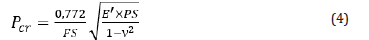
where Pcr is the critical buckling stress, FS is the safety factor, n is the Poisson ratio. Safety factors at around 2 have been used for polymer pipes [16], Poisson’s ratio for various thermoplastic polymers is of the order of 0.4. There is a direct correlation between the critical buckling stress and stiffness. Therefore, there will be reduction of the buckling capacity of the tube with plasticization of the polymer. The values obtained from the data listed in Table 3 are shown in Table 6.
Table 6:Critical buckling stress according to the deformation imposed on the tube and the aging effect.

Conclusion
From the results of the parallel plate compression tests performed following the procedures of ASTM D2412 it was determined that aging by immersion in hot water causes a reduction in the rigidity of PA pipes. Consequently, the mechanical stress required to compress the tube to a certain amount of deformation is reduced and there is increased deflection for a given applied constant load. Aging was associated with plasticization of the polymer and caused a reduction of the critical buckling load. Processing and digital image analysis showed that under the maximum deformation imposed in this study there was no difference between the geometry of the pipes either as-received or aged. That is, the tube deformation process is not changed but as stiffness decreases due to aging, the load required to produce the same deformation in aged pipes was on average 23% lower than in an unaged pipe.
From a practical point of view, excessive deformation can cause turbulent flow of the fluid being transported, which can lead to reduced life of the pipe by localized erosion. The combined effects of aging due to temperature and contact with water should therefore be considered in the design of this type of pipe. Preventive measures, such as placing rigid support elements along the length of the pipe, can minimize the effect of kneading the aged pipes and prevent excessive deformation.
Acknowledgement
The authors acknowledge the financial support from the Brazilian Funding Agencies CNPq and FAPERJ.
References
- Pang SS, Lea RH, Yang C, Stubblefield MA (1997) Advanced composite piping systems in offshore oil & gas industry. In: Proceedings of the fourth international conference on composites engineering, Hawaii, pp. 51-61.
- Scholten F (2008) Polyamide 11, 12 and 6.12 for high-pressure. In: Proceedings of the International Gas Union Research Conference, Paris, France, pp. 298-316.
- Wlodek T, Lawski L (2013) Application of pipelines made with Thermoflex® technology for natural gas and carbon dioxide transportation. AGH Drilling, Oil, Gas 30: 287-296.
- Wanasekara ND, Chalivendra V, Calvert P (2012) Effect of accelerated ultraviolet and thermal exposure on nanoscale mechanical properties of nylon fibers. Polymer Engineering and Science 52(11): 2482-2488.
- Maxwell AS, Broughton WR, Dean G, Sims GD (2005) Review of accelerated ageing methods and lifetime prediction techniques for polymeric materials. NPL Report, National Physical Laboratory, Hampton Road, UK.
- Torres AHU, d’Almeida JRM, Habas JP (2011) Aging of HDPE pipes exposed to diesel lubricant. Polymer-Plastics Technology and Engineering 50(15): 1594-1599.
- Zhou J, Lucas JP (1999) Hygrothermal effects of epoxy resin. Part II: variations of glass transition temperature. Polymer 40(20): 5513-5522.
- Torres AHU, d’Almeida JRM, Habas JP (2010) Creep behavior of high density polyethylene after aging in contact with different oil derivatives. Polymer Engineering and Science 50(11): 2122-2130.
- ASTM standard D 2412-08 (2018) Determination of External Loading Characteristics of Plastic Pipe by Parallel-Plate Loading. ASTM International, 100 Barr Harbor Drive, West Conshohocken, PA, USA.
- Czél G, Czigány T (2012) Image processing assisted stress estimation method for ring compression tests of polymer composite pipes at large displacements. Journal of Composite Materials 46: 2803-2809.
- Russ JC (2006) The image processing handbook. (5th edn), CRC Press, Boca Raton, USA.
- Paciornik S, Maurício MHP (2008) Digital imaging. In: Vander Voort GF (Eds.), ASM Handbook: metallography and microstructures. ASM International, Materials Park, USA, pp. 368-402.
- d’Almeida JRM, Paciornik S (2008) Evolution in the characterization of composite materials through digital microscopy. Materials Science Research Journal 1: 331-383.
- Maio VP, d’Almeida JRM (2015) Tensile behavior analysis of a polyamide pipe after aging into hot water. In: Proceedings of the 13th Brazilian Conference on Polymers, Natal, Portugal.
- Jeyapalan JK, Watkins R (2004) Modulus of soil reaction (E’) values for pipeline design. Journal of Transportation Engineering 130: 43-48.
- Gabriel LH. Design Methodology. In: Corrugated polyethylene pipe design manual & installation guide, Plastics Pipe Institute, Irving, Texas, USA.
© 2018 d’Almeida JRM. This is an open access article distributed under the terms of the Creative Commons Attribution License , which permits unrestricted use, distribution, and build upon your work non-commercially.
Editor In Chief


.jpg)


Signup for Newsletter

Quick Links
 Editorial Board Registrations
 Submit your Article
 Refer a Friend
 Advertise With Us
Our Recent Edition

.jpg)


Top Editors


.jpg)


.bmp)
.jpg)
.png)
.jpg)


.jpg)


.png)

.png)


.png)


Financial Support

Sponsors

Latest e-Books

Latest Video

 a Creative Commons Attribution 4.0 International License. Based on a work at www.crimsonpublishers.com.
Best viewed in
a Creative Commons Attribution 4.0 International License. Based on a work at www.crimsonpublishers.com.
Best viewed in