- Submissions

Full Text
Evolutions in Mechanical Engineering
Analysis and Optimization of Lower Control Arm
Kale AR1*, Tadamalle AP2 and Patil ND3
1 Post Graduate Student, Department of Mechanical Engineering, Sinhgad College of Engineering, India
2 Professor, Department of Mechanical Engineering, Sinhgad College of Engineering, India
3 Manager, R&D Department, Hanuman Engineering Works Pvt Ltd, India
*Corresponding author:Kale AR, Post Graduate Student, Department of Mechanical Engineering, Sinhgad College of Engineering, Pune, India, Email:abhi.kale1994.ak@gmail.com
Submission: June 25, 2018;Published: August 07, 2018

ISSN 2640-9690 Volume1 Issue1
Abstract
Control arm in automotive vehicle acts as a linkage between sprung and unsprung mass of vehicle. Lower control arm is subjected to various loads. Due to this type of loading, there are chances of bending of control arm. Hence failure of lower control arm occurs. Weight reduction of vehicle component is one of the main concerns. The aim of the paper is to analyze and optimize the lower arm using finite element analysis. The model of lower control arm is done in CAD software. Static analysis of lower control arm is carried out in analysis software. Topology optimization of lower arm is performed for weight reduction. After topology optimization static analysis of optimized lower control arm is carried out. Results obtained from analysis where studied to check whether the design is within the yield strength. Cost analysis of existing and optimized lower control arm has been carried out to know the cost effectiveness. The purpose of automobile suspension system is passenger comfort and vehicle control. The lower control is one of the important parts of suspension system.
Keywords: Lower control arm; Static analysis; Topology optimization
Introduction
In the automotive industry, handling qualities of car is an important issue. These qualities are greatly affected by the suspension system. The suspended portion of the vehicle is attached to the wheels. To cushion the impact of road irregularities suspension arm is connected. Suspension arm is the main component in automotive suspension system. It carries all the different loads created due to irregular roads. There are various types of suspensions like wishbone or double wishbone suspensions. There are lots of research works which consist of suspension system, different types of suspension system, upper and lower control arm. The lower control arm is subjected to many loads due to variation in gross weight and impacts due to fluctuation of road surface and additional forces. Beside all this technological advancement, there can be excessive stress development in lower control arm. During running condition, the arm is subjected to many loads [1]. The chance of bending and failing of lower control arm takes places because the complex nature of loads. These loads are due to fluctuation of road surface and additional forces like braking and cornering. Due to this chance of bending and hence failing of lower control arm takes place. Hence it is necessary to carry out static. In this paper static of lower control arm is performed. With help of finite element approach it becomes easy to carry out this analysis within short period of time [2]. With rapid development in technology there are different optimization techniques for weight reduction used in industries. Some of the techniques consist of topology optimization, shape optimization, material substitution etc. Weight optimization of components for vehicles is becoming more important. The application of topology optimization is done for weight reduction. This method is efficiently applied to weight reduction on lower control arm. Weight optimization of lower control arm is done, and results are checked for same.
Literature Review
Viqaruddin et al. [1] discussed the static analysis and torsion analysis of the control arm. To improve the stiffness of the control arm static analysis was carried out. In this paper weight reduction of component by changing the geometrical dimension and structural properties was done. This design is given by topology optimization for compare the base run analysis and optimized analysis. Todkar [2] focused on the finite element-based stress analysis of A Type lower suspension arm. The objective of this study is to calculate working life of the component under static loading. Wankhade [3] carried out the work to measure stress and temperature distribution of piston Topology optimization of piston is carried out using optistruct software. The critical areas where maximum stresses are generated are found out. Krishna [4] described the application of shape optimization techniques in the design of an upper control arm of an automotive suspension system. An existing design of an upper control arm has high stresses. The shape optimization was performed to carry out fundamental frequency. Schramm et al. [5] distinguished techniques to include manufacturability in the optimization process Structural optimization techniques are used in design of automotive structures. Thus, the goal of paper is topology optimization.
Methodology
The solid model of lower control arm is modeled using modelling software based on drawing provided by company. This model is then imported in analysis software for meshing. The meshed model is analyzed to check stresses and deformation. Lower control arm is analyzed and optimized using analysis and topology optimization. Optimization of lower control arm is done using optimization software. Analysis of optimized lower control arm is carried out to check whether the design is within the yield strength. Cost analysis of existing arm and optimized lower control arm has been carried out to know the cost effectiveness.
Modelling of lower control arm
The material selection is selected based on different factors like density, young’s modulus and yield tensile strength. The lower control arm is made up of mild steel. The material properties of mild steel are shown in following Table 1.
Table 1:Material properties of lower control arm.

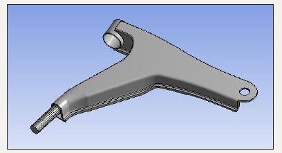
From the above table the yield tensile strength of mild steel is 350MPa. Thus, the stress value obtained after static analysis should be within the yield strength of material. Reverse engineering of lower control arm is done using special tools like vernier gauge, radius gauge etc. The modelling parameters are provided by the company. The modelling of lower control arm is done. In this paper CATIA V5 software is used as modelling software. The following Figure 1 shows the CAD model.
figure 1:CAD model of existing lower control arm
Meshing of lower control arm
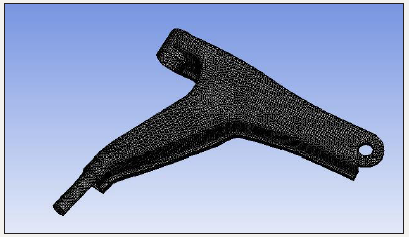
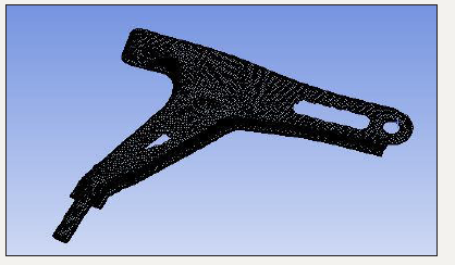
The meshing method used is patch conforming second order tetra element. Tetra elements are solid elements which have been extracted from 2D tri elements. This type of meshing is used as it consists of additional mid nodes due to which the deformation can be captured more accurately. The node population count is 154821 and element population count is 80483. Following Figure 2 shows meshed model lower control arm.
figure 2:Meshing of existing lower control arm.
Boundary conditions
The loads acting on the axle of vehicle are calculated. The load acting on front lower control arm is considered.
I. Calculate load acting on wheel of front axle: Mass of the vehicle (m)=1000kg
Wheel Base (S)=2100mm
Distances between CG and front axle (S1)=800mm
II. Formulae used
a) Weight of the vehicle acting at its center of gravity (G) G = m*g
b) Distance between CG and rear axle (S2) S=S1+S2
c) Load on front axle (GFA) GFA=G*S2/S
d) Load on Wheel of front axle (GFAW) GFAW=GFA/2 (Table 2)
Table 2:Design calculation values

Static Analysis of lower control arm
figure 3:Boundary condition
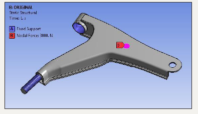
Structural analysis is used to calculate the stresses and deformation that are generated by the mechanical loads. It is done to determine the effect of loads on physical structure. The lower control arm is connected to the wheel and chassis of a car. The lower control arm experiences many loads. Due to these loads the lower control arm undergoes deformation. Due to deformation and cyclic loads the lower control arm fails. So, it is necessary to calculate the stresses acting on lower arm before manufacturing of arm. The maximum and minimum stresses are calculated for different loads using structural analysis. The maximum deformation is predicted using FEA software. The boundary conditions are applied for the same is as shown in Figure 3.
Topology optimization
figure 4:CAD model of optimized lower control arm.
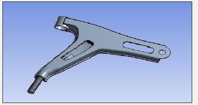
Optimization is a technique that optimizes the material within a given design space, for a given load, a boundary condition and constraints with a goal maximizing the performance of the system Optimization of lower control arm is carried based on the stress results of existing lower control arm. The weight of existing model is 2.6042kg. After optimization the weight of lower control reduced to 2.203kg. Figure 4 shows the optimized lower control arm. The meshing method used is patch conforming second order tetra element. Figure 5 shows the meshed model of optimized lower control arm. This meshing is used because it consists of additional mid nodes. Because of this the deformation is generated more calculatedly. The node and element count are 51288 and count 6965 respectively.
figure 5:Meshing of optimized lower control arm
Result and Discussion
Existing lower control arm
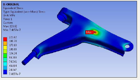
The existing lower control arm is subjected to the load due to which stress and deformation are developed. It is necessary to check whether the designed lower control arm is within the safe limit. The load on lower control arm applied is 3000N. The Figure 6 shows the displacement result of lower arm. The maximum deformation is 0.22545mm. The maximum deformation is obtained at the point where the unsprung mass is connected. The maximum von-Mises stress obtained is 223.62MPa. It is seen that stresses induced in lower control arm is less than yield strength (Figure 7).
figure 6:Total deformation of lower control arm.
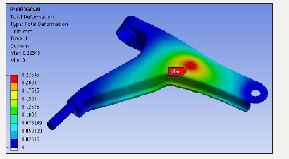
figure 7:Von-Mises stress of lower control arm.
Topology optimization of lower control arm
After the static analysis of lower control arm topology optimization is carried. The existing lower control arm is optimized using ANSYS. After optimization the weight of lower control reduced to 2.203kg. Static analysis of optimized lower control arm is shown below. The deformation obtained is 0.20941mm. The Figure 8 shows the deformation of optimized lower control arm. The maximum deformation occurs at the point which is connected to unsprung mass. The stress analysis of optimized lower control arm is done. The maximum von-Mises stress obtained is 240.59MPa.
figure 8:Total deformation optimized lower control arm.
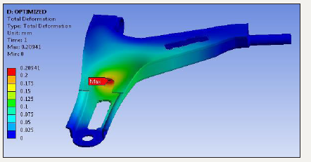
figure 9:Von-Mises stress of optimized lower control arm
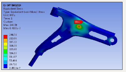
After optimization the weight of lower control arm reduced due to which stresses in the arm increased. Above Figure 9 shows the stress distribution of optimized lower control arm. The results obtained are within the yield strength of material. Hence, the design is safe after optimization for the given criteria. With this analysis the static analysis of existing and optimized lower control arm obtained are verified for yield strength. The comparative vonmises stress of existing and optimized lower control arm is shown in Figure 10.
figure 10:Von-mises stress of existing and optimized lower control arm.
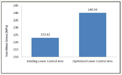
It is seen that the stress of optimized lower control arm is greater than existing lower control arm. The mass of optimized control arm is reducing hence the stress level of optimized control arm increases. The Figure 11 shows the comparison of deformation for existing and optimized lower control arm. It is seen that total deformation generated after optimization of lower control arm is less than existing lower control arm.
figure 11:Total deformation of existing and optimized lower control arm.

Cost reduction
The material cost of mild steel available in market is 50Rs/Kg. The existing lower control arm weighs 2.6042Kg. Raw material cost for lower control arm mild steel is calculated by using volume of material used, density and material cost per Kg. Hence the cost of raw material for existing control arm is Rs. 131. Also, hourly cost time required is Rs.6050 and cycle time for one piece is 17Sec. Hence, the machining cost foe existing lower control arm is Rs. 36. Tooling cost for lower control arm is Rs 240. Total production cost is Rs. 407 by considering raw material, tooling and machining cost. Raw material cost of optimized lower control arm is reducing to Rs 110. Also, machining cost for optimized lower control arm is Rs. 21 because the cycle time reduced up to 10sec. Hence the total production cost of lower control arm by considering raw material, tooling and machining cost is Rs 371. Hence, after optimization three is cost saving of 8.8%.
Conclusion
The result of stress generated by static analysis of existing lower control arm is 223.62MPa. After optimization the result obtained for stress analysis of optimized lower control arm is 240.59MPa. Thus, the design is safe according to yield strength criteria. The weight of existing lower control arm is 2.6042kg and that of optimized part is 2.203kg. Thus, the weight reduction is 15.39% by using optimized control arm. The cost saving by using optimized lower control arm over existing control arm is 8.8%.
Future Scope
The lower control arm undergoes many vibrations. Modal analysis of lower control arm can be done using ANSYS to check the natural frequencies and mode shapes. These modal frequencies can be validated experimentally using FFT analyzer.
References
- Viqaruddin M, Ramana DR (2017) Structural optimization of control arm for weight reduction and improved performance. Materials today: proceedings 4(8): 9230-9236.
- Todkar RG (2015) Design, analysis of a-type front lower suspension arm in commercial vehicle 3(7): 2395-2415.
- Wankhade LN, Zolekar N (2013) Finite element analysis and optimization of I.C. engine piston with RADIOSS and optistruct. Altair Technology Conference.
- Murali M (2005) Topology & topography optimization of a drive shaft. SAE Technical Paper Series, pp.3552-3563.
- Schramm U, Thomas H, Zhou M (2002) Manufacturing considerations and structural optimization for automotive components. SAE Technical Paper Series, pp.4-7.
© 2018 Kale AR. This is an open access article distributed under the terms of the Creative Commons Attribution License , which permits unrestricted use, distribution, and build upon your work non-commercially.
 a Creative Commons Attribution 4.0 International License. Based on a work at www.crimsonpublishers.com.
Best viewed in


.jpg)


 Editorial Board Registrations
 Submit your Article
 Refer a Friend
 Advertise With Us
.jpg)


.jpg)


.bmp)
.jpg)
.png)
.jpg)


.jpg)


.png)

.png)


.png)


