
- About Us
- Information
-

The Author ensures that the research has been conducted responsibly and ethically with adherence to all relevant regulations. read more..
- For Authors
- For Reviewer
- Manuscript Guidelines
- Membership
- Publication Ethics
-
- Journals
- Reprints
- e-Books
- Videos
- Policies
- Contact Us
 COVID-19
- Submissions


Full Text
Determinations in Nanomedicine & Nanotechnology
Application of protective coatings to the surface of channels of medical instruments
Vladislav Smolentsev*, Sergey Safonov and Andrey Mandrykin
Department of Engineering Technology, Russia
*Corresponding author: Vladislav Smolentsev, Department of Engineering Technology, Moscow Avenue 14, Voronezh, Russia
Submission: February 26, 2020;Published: March 11, 2020

ISSN: 2832-4439 Volume2 Issue1
Abstract
The paper discusses the features of the manufacture of small cross-section channels with high geometric accuracy, characteristic of the nozzles for the supply of gaseous, liquid and mixed media. In transport equipment, thermal power systems are widely used nozzles with one or more channels of supply of working media, the diameter of which is measured in fractions of a millimeter. In the process of manufacturing such products requires the removal or build-up of small (within one or more microns) layers in separate holes for the supply of working media, which allows you to align the flow of liquid through all holes, to provide the required flow rate and spray the combustion products supplied, for example, for rocket engines, where up to 200 nozzles can work simultaneously gorenjes. A new method of coating the inner surface of the holes of any section using a combined treatment with simultaneous action of the electric field and the radial pressure of a given value is proposed. The calculation of parametroa of the tool and technological conditions, which ensures high accuracy of the flow path of the injector and the resistance of the coating when applying aggressive flammable fluids
Introduction
Build-up of quality layers in holes with a diameter of less than 2-3mm causes serious difficulties. Used electroplating processes do not always ensure the accuracy and quality of the applied layer, especially in openings with a cross section less than 1mm2, and optionally, the coatings of the nanoscale. The studies carried out in recent years have made it possible to develop a new method [1] for controlled application of discrete coatings with a layer thickness of less than 0.1μm and a quality that meets the requirements of technologists when debugging the flow path of nozzles [2] for the flow and spray of working media.
The mechanism of deposition of nanolayers by galvanotechnics processing
In traditional galvanic coating it is difficult to provide compressive stresses in the surface layer, which reduces their adhesion and can cause the surface layer to crumble in the hole. This is not allowed in the case of fine-tuning and calibration of injectors, as the ingress of even microparticles in the flow of small cross-section channels can cause a violation of the supply of the working environment and, for example, the failure of aircraft engines. In [3], a method for producing high-quality nanolayers with a thickness of less than 0.1μm, the number of which can reach several thousand, is proposed. At the same time, high adhesion of the layers, the absence of microcracks, which is especially important when pumping through the channels of aggressive media (for example, acids), liquid gases with high oxidative activity (for example, oxygen), causing corrosion of the inner surface of the hole under the coating layer and the destruction of the nozzles. A feature of the Galvano mechanical method [1] is the need for rolling or rubbing a thin layer of coating with a tool made of a solid material (for example, from ceramics) with an adjustable clamping force, which allows even before the formation of the granular structure of the coating (with galvanic deposition, a large [3] to a fraction of a millimeter, grain) to create compressive stresses in the nanolayer and prevent the latter from crumbling.
Quality assurance of nano-coating
Studies conducted on an electron microscope and x-ray diffraction method showed that due to mechanical action of a solid tool can be obtained coating structure close to the metal glass, although [3] indicates that there is a microcrystalline structure of the material with a grain of up to 1.5 microns, which is up to 100 times less than the precipitation obtained by electroplating. Even taking into account the possibility of the appearance after Galvano mechanical coating of fine grain, the tightness of the coatings ensures the absence of leaks through it until the pressure drop is more than 25MPa (test duration is 3 minutes) [3]. The surface roughness of the coating is achieved Ra=0.18-0.2μm, which is one of the main indicators of the high quality of the flow path of the nozzles operating at high flow rates and pressure drops of the pumped medium up to 20-25MPa.
The unevenness of the coating layers does not exceed 2-3% of the thickness, although this implies a high accuracy of the original channel profile, the achievement of which, as a rule, requires large costs. An interesting solution for Galvano mechanical chromium plating was obtained in [1,4], where the previously known fact of a sharp increase in the rate of chromium deposition with a decrease in the contact pressure of lapping (10 or more times) was used. However, the intensification of the process causes a significant reduction in the quality of the coating (continuity, microhardness, etc.). According to the method [1,5], it was possible to apply layers of variable thickness, filling areas with a large allowance, after which, at the recommended contact pressure, a quality layer was obtained that provides operational requirements for the product. The method [1] can be useful to restore the geometry of the channels in local violations of their geometric dimensions and to obtain high-quality flow paths, even if it is necessary to apply coatings of micro-thickness.
Processing modes and technological parameters
As a result of the studies conducted in [4] obtained the technological modes of application of nano-coating applied to galvanotechnics chrome:
A. Current density, kA/m2: 10-15.
B. Electrolyte Cr2O3: 250g/l; H2SO4: 2.5g/l.
C. The temperature of the electrolyte, To: 330-340 0C.
D. Contact pressure, MPa: 1-2.
E. Thickness of the applied quality layer in one pass of the tool, μm: 0.2-1.0.
Technological parameters of Galvano-mechanical chrome plating of internal surfaces are studied and their quantitative assessment is received: -performance (chromium deposition rate)- 1-5μm/min; -surface roughness, Ra - 0,018-0,63μm; -accuracy of coating thickness (with coating thickness of 445μm) and 2.5μm; the microhardness of coating is up to 11530MPa; -residual compressive stress-100-300MPa;-high adhesion;-tightness-provided (dense non-porous coating); -maximum coating thickness -up to 800 microns; -increased wear resistance of contact pairs due to coating -1.9 -4.0 times; -flooding -within standard limits.
Technology of application of nano
In [2] it is shown that the use of technological schemes given in [3,4] is not feasible for holes of small diameter (less than 6-8mm), as to move in the hole of the tool for rolling requires a space of more than 8-10mm. Therefore, a new scheme of Galvano mechanical coating is proposed (Figure 1).
The principal difference between the scheme shown in Figure 1, from the known is the combination in a single tool (electrodetool 2 in Figure 1) and the Dorn element (in the form of strips 3). In addition, the limited space between the tool (2) and the hole (1) requires dosing of the working medium 4; the small cross-section of the tool (2) leads to the need to limit the force (P) to the tensile strength of the tool-wire. To ensure the required contact pressure of the mandrel belts (3) with the coating (5), the cross section of the belts is reduced in the direction opposite to the movement of the tool by the coating value.
Figure 1: Scheme of application of nanocoating’s of small cross-section holes (on the example of the nozzle) 1. The main channel in the housing 2. Of the injectors. 3. Channel in the nozzle injector. 4. Electrode wire. 5. Carnousie dielectric belts. 6. Liquid working medium; R- the force of pulling the electrode wire.

Calculation of the electrode-tool
Calculation of the main parameters of the electrode–tool, shown in Figure 1, includes: estimation of the number (n1) simultaneously located in the hole of the Dorn belts
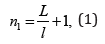
where L is the length of the hole; l is the step between adjacent belts (usually 1/2L).
Given the need to move the tool along the hole, the number of supports in the form of doronuma belts 3 The length of the tool (Li) for processing the hole length L will be
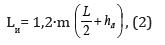
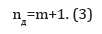
where-the width of the Dorn belt; 1,2-coefficient, taking into account the technological areas of the tool; m-the number of passes of the tool. The quantity (nд) Dornbush corbels on the tool
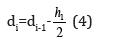
The diameter of the mandreling belts (di) is reduced along the length of the tool by the amount of the applied layer (h1/2) by half the length of the hole, while d1=d0 (d0 is the diameter of the hole before coating). Then
Tool diameter–wire (dпр) is calculated on the basis of the need for accommodation in the space (Vidt) between adjacent dornowski bands of electrolyte volume sufficient for performing a chemical reaction on the deposition of the desired layer thickness (h1/2) for the period of the promotion instrument for the length L/2 . Hence the section of wire Sп
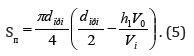
where Vi is the volume content of metal in it (in this electrolytechromium) per unit of its volume (V0).
For the diameter of the wire tool D, find the area of its section
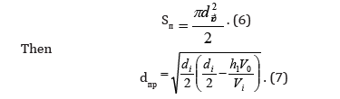
The value dпр are rounded to standard values dпс.
The condition of using the wire of the selected diameter is to maintain its tensile strength (σa) when pulling through the hole with a force P (Figure 1), which is calculated in the design of processing modes.
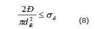
If the condition (8) is not met, then the value of h1 is reduced, thereby reducing the volume of a single coating, increasing the diameter of the wire. After finding the dps determine the interelectrode gap (S3)
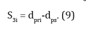
The value of S3i must be at least 0.02mm, otherwise short circuits may occur. Taking into account the parameters of the tool, the technological process of nanocoating is designed. The force P of the wire tool movement in the hole (Figure 1) is calculated by [5] and adjusted by the criterion (8)
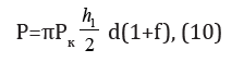
where Pk - pin power ([3] PK = 1-2MPa); f - coefficient of friction, depending on the material of the belts and coating (selected by reference).
Conclusion
A. A method for obtaining high-quality nanocoating’s applied to the surface of small cross-section channels is proposed. The method combines electroplating of mechanical layers of nano tole with simultaneous mechanical rolling of the coating, which allows to achieve high accuracy of holes, adhesion, wear resistance.
B. Developed design tools for combined galvanomagnetic processing. This makes it possible to calibrate small-section holes, for example, in nozzles, by successive deposition of nanocoating’s and obtain high quality of each layer, which previously was not used for the small-section channel.
References
- Smith JM. Chemical engineering kinetics. Book Chemical Engineering Series 209: 74-99.
- James JC. Book chemical engineering series. University of Notre Dame, USA.
- Akbari MR, Ganji DD, Nimafar M, Ahmadi AR (2014) Significant progress in solution of nonlinear equations at displacement of structure and heat transfer extended surface by new AGM approach. Frontiers of Mechanical Engineering 9: 390-401.
- Rostami K, Akbari MR, Ganji DD, Heydari S (2014) Investigating Jeffery-Hamel flow with high magnetic field and nanoparticle by HPM and AGM. Cent Eur J Eng 4(4): 357-370.
- Akbari MR, Ganji DD, Majidian A, Ahmadi AR (2014) Solving nonlinear differential equations of vanderpol rayleigh and duffing by AGM. Frontiers of Mechanical Engineering 9: 177-190.
- Ganji DD, Akbari MR, Goltabar AR (2014) Dynamic vibration analysis for non-linear partial differential equation of the beam-columns with shear deformation and rotary inertia by AGM. Development and Applications of Oceanic Engineering (DAOE).
- Akbari MR, Ganji DD, Ahmadi AR, Sayyid HHK (2014) Analyzing the nonlinear vibrational wave differential equation for the simplified model of tower cranes by (AGM). Frontiers of Mechanical Engineering 9(1): 58-70.
- Akbari MR, Nimafar M, Ganji DD, Akbarzade MM (2014) Scrutiny of non-linear differential equations Euler Bernoulli beam with large rotational deviation by AGM. Frontiers of Mechanical Engineering 9: 402-408.
© 2020 Vladislav Smolentsev. This is an open access article distributed under the terms of the Creative Commons Attribution License , which permits unrestricted use, distribution, and build upon your work non-commercially.
Editor In Chief


.jpg)


Signup for Newsletter

Quick Links
 Editorial Board Registrations
 Submit your Article
 Refer a Friend
 Advertise With Us
Our Recent Edition

.jpg)


Top Editors


.jpg)


.bmp)
.jpg)
.png)
.jpg)


.jpg)


.png)

.png)


.png)


Financial Support

Sponsors

Latest e-Books

Latest Video

 a Creative Commons Attribution 4.0 International License. Based on a work at www.crimsonpublishers.com.
Best viewed in
a Creative Commons Attribution 4.0 International License. Based on a work at www.crimsonpublishers.com.
Best viewed in