- Submissions

Full Text
COJ Reviews & Research
Hybrid Materials-Historical Perspective and Current Trends
Merve Aksit and Volker Altstädt*
Department of Polymer Engineering, Germany
*Corresponding author: Volker Altstädt, Department of Polymer Engineering, Faculty of Applied Natural Sciences (FAN) of the University of Bayreuth, Germany
Submission: December 19, 2019; Published: January 10, 2020

ISSN 2639-0590Volum2 Issue3
Abstract
The definition for a hybrid material by the International Union of Pure and Applied Chemistry is based on a chemical point of view that “A hybrid material is composed of an intimate mixture of inorganic components, organic components, or both interpenetrate on sales of less than 1μm.” For instance, polymer blends of polyphenylene oxide/styrene-acrylonitrile copolymer compatibilized by a triblock terpolymer and Janus particles exhibit a sub-micron level contribution of different kinds of organic components. At the same time, engineers look at hybrid materials from a different scale with no uniform definition. According to the engineering point of view; hybrid materials combine different material classes within one structural material. For example, Glass Laminate Aluminum Reinforced Epoxy is used as a hybrid material in the upper part of the fuselage of the Airbus A380 aircraft. Besides structural applications, food packaging materials are also considered as hybrid materials. As an example, milk packages are composed of polymer (low-density polyethylene), paperboard and aluminum. In this work, it was aimed to give an interdisciplinary overview to the world of hybrid materials transferring the view from chemistry to the applied engineering science by focusing on different material aspects and trends.
Keywords: Polymer blends; Janus particles; Supramolecular additives; Polymer foams; Composites
Introduction
Hybrid materials are one of the most important material classes which have been used for more than 2 million years in a variety of applications in human life. For example, the Stone Age people developed hybrid materials to be applied as weapons for protection and hunting where people from Neolithic Age used them to construct their houses [1]. With developing technology and by time, hybrid materials got even more complex in design and shapes. Today, they have been started to be applied in more fields such as aircraft industry. The hybrid material made of a metal-glass-epoxy prepreg layers for aircrafts was obtained by a combination of two or more different materials. It features superior properties to the material such as, lightweight, low cost, higher impact properties and chemical resistance, compared to the conventional materials used in aircrafts like aluminum [2]. Despite its longterm history, the distinct definition of hybrid material is not very clear to the researchers from different disciplines. The definition of a hybrid material varies interdisciplinarily (e.g. Biology, physics, chemistry or engineering). The present review covers the historical perspectives and definitions of hybrid materials, in particular from chemists´ and engineers´ view. The definitions will be then supported with the corresponding research studies from literature, examples and their applications.
Historical Perspective of Hybrid Materials
Hybrid materials in the history of human being
Hybrid materials have been a significant part of human life since the Stone Age. The tough life conditions brought the ancient people to develop their own technologies to cope with challenges as well as for protection and hunting. They built up weapons made of hybrid materials consisting of more than one material. For instance; scrapers, hand axes, spears and arrows. In Paleolithic Age, the wood was used for the shaft. Animal sinews and plant fibers were used for fixing a stone to the tip. After sharpening and carving the stone, the weapons were ready to use [1]. With the development of metals, the Mesolithic Age people developed more complex tools such as stone tools with “microliths” which are small pieces, often having a geometric form such as triangular, square or trapezoidal (Figure 1) and small trimmed blades mounted in various combinations to create different tools [3-5]. Besides weapons, the people from Neolithic Age used hybrid materials such as a straw (organic fiber) and a clay (inorganic matrix) to construct houses. In 8th century, before common era (B.C.), the Egyptian developed a hybrid bowl which is made of horn, wood and sinew by laminating the materials together. The Egyptian bowl with arrows was also used as weapon. The old dye Maya Blue which was formed by a good mixture of vegetable dye “indigo”, inorganic clay mineral “palygorskite” and copal resin. This is another example for the application of a hybrid material from Mesoamerica between 3rd and 10th century [6].
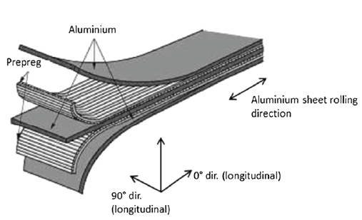
With improving technology, the hybrid materials were used in variety of applications. For instance, the glass laminate aluminum reinforced epoxy (GLARE®) is a fiber-metal laminate that is widely applied as an alternative to conventional aluminum in aircraft industry. It was patented in 1987 by AKZO [7]. In 1997, a partnership between AKZO and ALCOA started to operate the production and commercialization of GLARE®. It is a hybrid material having a certain number of very thin metal (e.g. Aluminium) sheets as interlayers between several glass fiber / epoxy prepreg layers. The prepreg layers can be plied cross or uni-directional depending on the anticipated stress conditions in corresponding application [8-10]. The structural design of a GLARE® panel is illustrated in Figure 2. The strategy of combining more than two materials features some benefits, such as a higher impact and fatigue resistance, being lighter and cheaper, with better corrosion and fire resistance, compared to conventional aluminum. In addition, due to the flexibility in manufacture, the parts with even very complex design and shape may be produced by tailoring the number, type and alignment of layers depending on the stress throughout the aircraft [5,8]. All these advantages over aluminum made the aircraft over aluminum led Airbus to employ GLARE® in their aircraft A380, starting from year 2001. In 2005, the first flight of the A380 took place with 27 panels of GLARE® in the upper fuselage cut. The panels made of GLARE® featured 30% weight reduction and much more reliability than aluminum on the long run [11]. Furthermore, one of today’s most used application of hybrid materials is the food packaging industry, such as chips packages (metallized multilayer polymer film) [7], stand-up pouches (polymer-aluminum laminate) [12] and beverage package (polymer-aluminum-paper board) [12]. For instance, a milk package is a hybrid consisting of six layers of three different materials. The materials corresponding to each layer from outside to inside of the package are as follows: Polyethylene (PE)-paper board-PE-Aluminum-PE-PE [12].
Figure 1: Microliths with different geometries (modified from) [15]. (Reproduced with permission of Springer Nature).

Figure 2: Illustration of the structure designs of a hybrid GLARE® panel [10]. (Reproduced with permission of Springer Nature).
Definitions of Hybrid Materials
Although hybrid materials play a significant role in our daily life from the Stone Age until today, the definition of hybrid material is not totally clear and varies depending on the scientists view from various research fields. For instance, a biologist, a physicist, a chemist and an engineer may define hybrid material differently. The main two perspectives of chemists and engineers with corresponding examples and applications will be discussed in the following sections.
Perspective of chemists
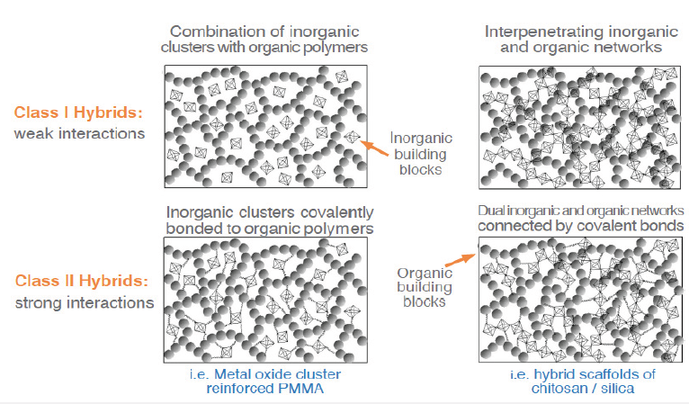
The chemist Makisima, has classified materials in four categories: Composites, nanocomposites, hybrids and nanohybrids. According to Makisima, when materials consisting of a matrix are dispersed in a micron-level, they are called “composites”. When similar kinds of materials are mixed on sub-micron scale, then they are called nanocomposites. The scientist defined hybrids and nanohybrids as a “Sub-micron level mixture of different kinds of materials.” and “Atomic or molecular level mixture of different materials with chemical bonds between these different materials.”, respectively [13]. Another definition was given in 2007 by the International Union of Pure and Applied Chemistry (IUPAC) as “Material composed of an intimate mixture of “inorganic” components, “organic” components, or both types of components. Note: The components usually interpenetrate on sales of less than 1µm.”. According to the IUPAC definition, the ultimate mixture of inorganic-inorganic, organic-organic or inorganic-organic components on sub-micron scale counts as hybrid [14]. Kickelbick [14] has categorized the hybrid materials according to the strength of the interactions of the organic and inorganic building blocks in two classes: Class I (weak interactions) and Class II (strong interactions) hybrids. Class I hybrids may be built up by a combination of inorganic clusters with organic polymers (e.g. Zeolite/Low-density polyethylene hybrid) or interpenetration of inorganic and organic networks (e.g. Ring-opening metathesis of a polymer with a silica network)). Class II hybrids may be formed when inorganic clusters are covalently bonded to organic polymers (e.g. Metal oxide cluster reinforced Poly (methyl methacrylate)) (PMMA) or dual inorganic and organic networks connected by covalent bonds (e.g. Hybrid scaffolds of chitosan/silica)). The schematic illustration of Class I and Class II hybrids is shown in Figure 3; [14].
Figure 3: The schematic illustration of the Class I and Class II hybrids (modified from) [14]. (Reproduced with permission of American Chemical Society).
A first example of a hybrid material (Class I) is a binary blend of poly (2,6-dimethyl-1,4-phenylene ether) (PPE) / poly (styrene-co-acrylonitrile) (SAN) in which two kinds of organic components are mixed on sub-micron scale. The strategy of blending of two polymers is the key to combine advantageous properties of two blend components and to achieve materials with a set of desired properties. In case of the PPE/SAN hybrid, PPE features high heat distortion temperature and flame retardancy without halogens while SAN provides good processability, high rigidity, chemical and stress corrosion resistance at low prices [14-16]. However, the week interfacial interaction between the two components leads to incompatibility, and thus weakened mechanical properties such as poor fracture toughness [17]. To address this, Ruckdäschel et al. [17] used ABC triblock terpolymers, namely polystyrene-block-polybutadiene-block-poly (methyl methacrylate) (SBM) as a compatibilizer to improve the interfacial interaction between PPE and SAN. This study is an example of a class II hybrid material which was obtained by the interaction of three organic components (PPE, SAN and SBM) on sub-micron level. The authors selected a blend system of PPE/SAN with a blend ratio of 60/40 as a reference system. The reference system, PPE/SAN (60/40) blends with 5, 10 and 20wt% SBM were melt blended by using a co-rotating twin-screw extruder with a screw length to diameter ratio of 30. The subsequent injection molding of the extruded granulates were carried out to obtain specimen for characterization tests. The thermodynamic interaction between the polystyrene (PS) and PMMA blocks and the blend components led to a discontinuous distribution of polybutadiene (PB) at the interface and results in a “raspberry” morphology which was reported for the first time in 1993 by Auschra & Stadler et al. [15,18]. The morphology is shown in Figure 4 schematically.
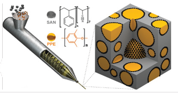
According to Figure 4, SBM is located in the interface between PPE and SAN, where the PS block is miscible in PPE and the PMMA block is miscible in SAN. The triblock terpolymer not only decreased the interfacial tension but also the coalescence leading to a finer morphology (smaller domain size). The improved microstructure featured a significant enhancement in both static and dynamic mechanical properties of the hybrid system. Improved ductility and fatigue crack propagation resistance were achieved while maintaining a high strength and modulus [17]. Furthermore, Bahrami et al. [19] developed another class II hybrid material including organic components of PPE, SAN and Janus Particles (JPs). The researchers used JPs as a novel compatibilizer for PPE/SAN blends. JPs are defined as non-centrosymmetric, anisotropic, colloidal nano particles with two strictly phase separated hemispheres, PS and PMMA (Figure 5). JPs, which were synthesized from an SBM precursor by cross-linking of the PB block of the SBM. JPs with concentrations of 2, 4 and 10wt% were melt blended via twin-screw extruder with PPE/SAN (60/40) (Figure 6).
Figure 4: Schematic illustration of the “raspberry” morphology of PPE/SAN blends compatibilized by SBM triblock terpolymers[17]. (Reproduced with permission of Elsevier).

Figure 5: Schematic of a JP made by cross-linking of PB middle block of SBM (modified from) [19]. (Reproduced with permission of American Chemical Society).

Figure 6: Illustration of the melt blending of PPE/SAN compatibilized by JPs (black dots) via extrusion; PPE droplets and SAN matrix are indicated in orange and grey, respectively [19]. (Reproduced with permission of American Chemical Society).
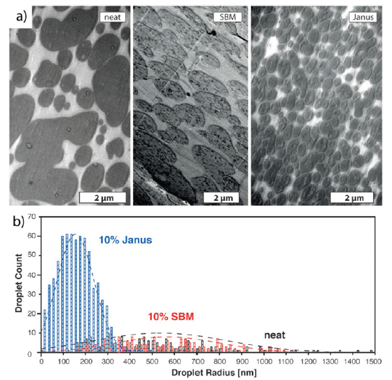
The researchers determined the effect of compatibilizer on the morphology and properties of the blend systems in comparison with SBM triblock terpolymers. The neat PPE/SAN blend system led to a co-continuous morphology (parallel to the extrusion direction) where PPE domains possess irregular and elongated shapes. 10wt% JPs led to a significant improvement in blend morphology exhibiting the droplet morphology with small domain sizes. PPE domains exist as regular and small droplets having diameters lower than 1µm. The authors compared the morphology, droplet size and its distribution of neat PPE/SAN blend, blend systems compatibilized by 10wt% JPs and 10wt% SBM. Figure 7 shows the different morphologies and a histogram of the domain sizes for all blend systems. Figure 7 exhibits the great potential of JPs to be used in PPE/SAN blend systems as an effective compatibilizer where they provide much lower droplet sizes (r) of 155±85nm and uniform morphology (narrower droplet size distribution) compared to those of the neat blend r = 540 ± 300nm and the blend with 10wt% SBM (r = 670±230nm). A further study from Bahrami et al. [20] showed the influence of JPs on the mechanical properties, in particular the fatigue crack propagation (FCP) of PPE/SAN (60/40). The testing of FCP is generally composed of three steps. In the first two steps, crack initiation and propagation in the polymer matrix lead to FCP. In the third step, the final failure of the polymeric material under alternating loading mainly occurs by fracture at the specimen. In addition, the scatter in the FCP rates gives a valuable information about the uniformity of the material. The fracture surfaces of the tested specimen are usually correlated with the three regions of different crack propagation rates to evaluate the fracture mechanism of the polymer. The first region corresponds to a very slow crack growth rate where the curves approach a threshold value of the stress intensity factor (ΔK), that is, no crack growth. In the second region, much of the crack life takes place and, for small ranges of ΔK. The third region corresponds to dramatically high crack growth rates, where instability and final failure occurs [21]. The FCP behavior of the PPE/SAN blend compatibilized with SBM was also analyzed to establish the structure property relationships between blend morphology and FCP behavior. The researchers followed the same processing as in the previous work to produce blends systems of neat PPE/SAN (60/40), PPE/SAN/JPs (60/40/10) and PPE/SAN/SBM (60/40/10). Furthermore, with the combination of four organic components of PPE/SAN/JPs/SBM (60/40/5/5) a hybrid blend system (Class II) was produced to investigate the synergistic effect of the compatibilizers SBM and JPs on the blend morphology and properties. Figure 8a depicts the morphology of the hybrid material PPE/SAN compatibilized with 5wt% JPs and SBM. Figure 8b shows FCP rate (da/dN) over stress intensity factor (∆K) curves of the PPE/SAN blend with both compatibilizers (5wt% SBM+5wt% JPs), without compatibilizer (neat), 10wt% JPs and 10wt% SBM.
Figure 7: (a) The morphologies of the PPE/SAN (60/40) neat, with 10wt% SBM and 10wt% JPs; (b) Droplet size and its distribution of 500 PPE domains in a SAN matrix [19]. (Reproduced with permission of American Chemical Society).
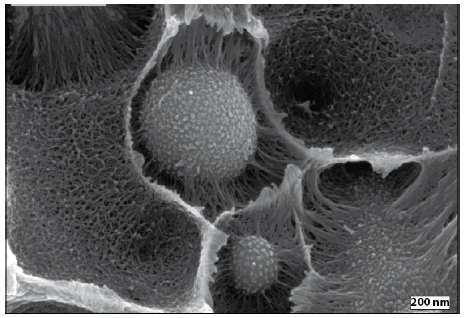
According to Figure 8a, the combination of SBM and JP (5wt% each) features a blend morphology with very small PPE droplets having a radius (r) of 100±50nm dispersed in the SAN matrix. The mean droplet size is found to be even smaller than in the blends compatibilized with either 10wt% SBM or 10wt% JPs. This might be due to the higher blend viscosity which was found to be 10 times higher than the viscosity of a PPE/SAN blend system compatibilized with 10wt% JPs only. The authors claimed that the higher viscosity results in higher shear forces in the extruder, and thus effective droplet break-up and smaller domain sizes of PPE. Figure 8b exhibits that the blend system compatibilized with only 10wt% SBM behaved like the neat blend in region I and caused deteriorated FCP behavior in region III. This was explained with a crazing and fibril formation around the interface area which is makes the interface stiffer due to the partially crosslinked PB middle block (Figure 9). Figure 9 demonstrates the strong interaction of the organic component JPs at the PPE/SAN blend interface to form a class II hybrid material. The authors stated that the strong and high entanglement density at the interface may hinder the debonding of the PPE particles from SAN matrix leading to macro cracks, in which a lot of energy is dissipated. Contrary to JPs, 10wt% SBM provided improved FCP behavior in the first two regions compared to one of the neat blends due to an elastic interface induced by the soft PB middle block. It was stated that until region III, the soft block allows macro crack initiation. The initiation occurred due to the tearing of the PB which dissipates noticeable amounts of energy. At region III, the tearing at the interface by PB cannot hinder the high-speed crack propagation anymore. Therefore, no improvement at this region was observed. The FCP behavior of the blend compatibilized with both JPs and SBM, has the best FCP resistance in both regions of threshold (Region I) and the critical fracture region (Region III) compared to those of all other blends. A significant enhancement in FCP resistance of PPE/SAN/JPs/SBM blend compared to one of the neat blends was found to be 43% and 20% in Region I and III, respectively. In shorter words, combining the JPs with SBM results in a synergistic effect on fine tuning the morphology as well as improving the mechanical properties [20].
Figure 8: Transmission electron microscopy (TEM) image of the 60/40 PPE/SAN blend with (a) 5wt% SBM + 5wt% JPs and; (b) FCP behavior of the blends with both compatibilizers (5wt% SBM + 5wt% JPs) compared to the neat blend, blends with 10wt% SBM and 10wt% JP (modified from) [20]. (Reproduced with permission of Elsevier).
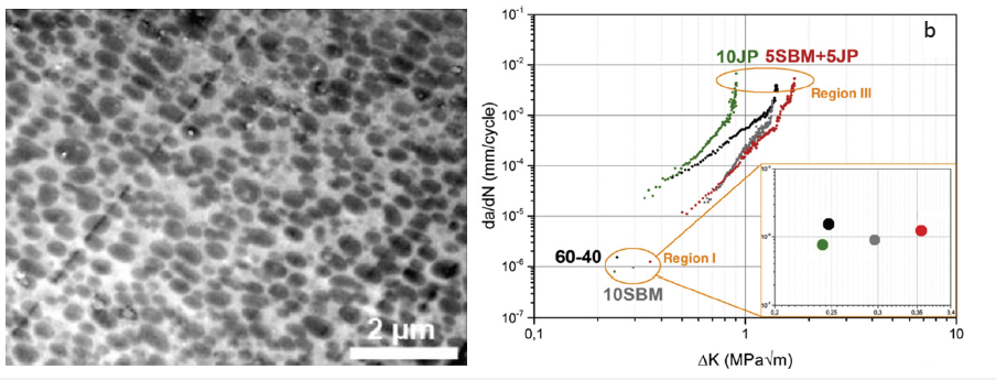
Figure 9: SEM image of JP at the interface of a PPE/SAN blend system (modified from) [20]. (Reproduced with permission of Elsevier).
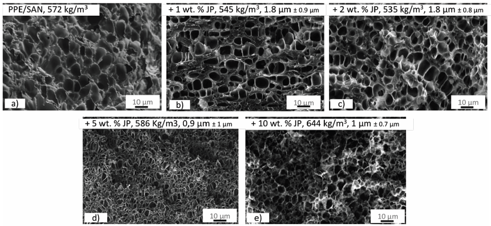
Furthermore, Baerwinkel & Bahrami et al. [22] achieved foams of PPE/SAN blends compatibilized by JPs. The authors reported that JPs act as a compatibilizer for the immiscible blend of PPE/SAN by forming a raspberry structure at the interface. They stated that JPs, which lead to blends with a decreased and uniformly dispersed PPE domains, are great candidates to be used as a foam nucleating agent (NA). Therefore, they have a great potential to achieve foams with lower cell sizes and a narrow cell size distribution. With this purpose, class II hybrid materials of PPE/SAN (60/40) with various concentrations of JPs were used to produce foams via a temperature-induced batch foaming method at 140 °C for 10s after 24h saturation with CO2 at 40 °C and 40 bars. Figure 10 exhibits a two-component hybrid foam of neat PPE/SAN and hybrid foams, in which the cell walls are composed of three organic components of PPE, SAN and 1, 2, 5 and 10wt% JPs. Furthermore, Figure 11 shows the influence of JPs concentrations on the cell size and density.
The SEM image of the neat PPE/SAN blend foam (Figure10a) depicts that foamability of the neat blend is quite bad. The authors reported that due to the very in homogeneous foam morphology and partially non-foamed areas throughout the sample, it was not possible to evaluate the cell size of the neat foam. In addition, it was claimed that the mean cell size decreases due to reduced domain sizes of PPE induced by JPs which leads to more foam cell nucleating sites. The lowest cell size of 900nm was achieved with 5wt% JPs at the density of 586kg/m3. A further increase in JPs content to 10wt% led to densely packed PPE domains which hinder the further expansion and cell growth of the foam and resulted in to increase in foam density from 586kg/m3 to 644kg/m3. 2wt% JPs led to PPE/SAN blend foams with a minimum density of 535kg/m3 but larger mean cell size of 1.7µm. The authors stated that greater cell diameters might be due to the weak interfacial tension between PPE and SAN, featuring a foaming of SAN phase into larger cells instead of foaming of PPE phase [22].
Figure 10: SEM image of JP at the interface of a PPE/SAN blend system (modified from) [20]. (Reproduced with permission of Elsevier).
In addition, Weiss et al. [23] developed a class II hybrid material based on PS, PMMA and kaolinite-based hybrid JPs (K-JPs) which was used as compatibilizer for PS/PMMA blend. K-JPs were composed of an inorganic kaolinite, which is a natural fine-grained layered silicate having diameters of smaller than 2µm, height up to 70nm and a specific surface area of 4m2/g, in which the two organic opposing basal planes, the tetrahedral (TS) and the octahedral (OS) surface, are layered by distinct functional groups. The sub-micron level interaction of these organic functional groups of K-JPs with two organic components of PS and PMMA is a good example for class II inorganic-organic hybrid materials. The SEM image of the kaolinite, the schematic illustration of kaolinite layers as well as their crystal structure with functional groups at the basal planes TS and OS are exhibited in Figure 12. The authors reported that the basal planes, TS and OS, enhance the compatibility between PS and PMMA. They claimed that the compatibility was provided by the polar nature of the kaolinite core of the JPs and the selective modification of the basal planes. For instance, a simple cation exchange of TS with poly (2-(dimethylamino)ethyl methacrylate) polycations leads to an attachment between TS and PS block whereas the OS and PMMA were bound covalently via catechol groups. In this study, PS/PMMA blends (30/70) with 5wt% K-JPs were prepared by a solvent casting process. Figure 13 shows the TEM image of the PS/PMMA film with 5wt% K-JPs.
Figure 11: Correlation of the cell size and foam density of PPE/SAN blend foam with various JPs concentrations [22]. (Reproduced with permission of John Wiley and Sons).
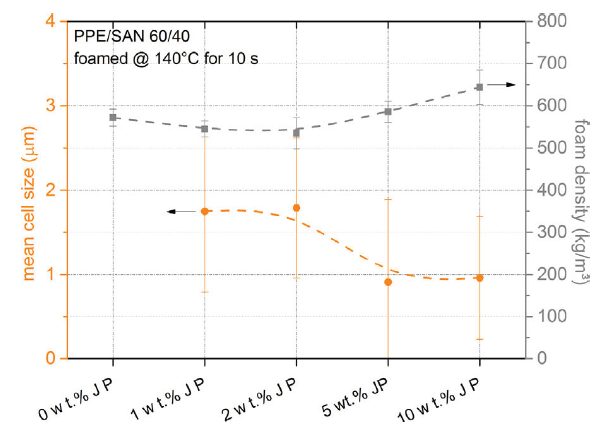
Figure 12: Correlation of the cell size and foam density of PPE/SAN blend foam with various JPs concentrations [22]. (Reproduced with permission of John Wiley and Sons).

Figure 13: TEM image of PS/PMMA (30/70) blend film with 5wt% K-JPs (modified from) [23]. (Reproduced with permission of Elsevier).
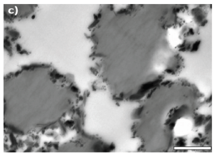
According to Figure 13, K-JPs (black) are located at the interface between PS (dark grey) domain and PMMA (grey) matrix. It was stated that a full coverage of the interface by K-JPs leads to very a low interfacial tension at the interface resulting in very small PS domains in a PMMA matrix. While the PS domains in neat PS/PMMA were in the range of several µm, 5wt% K-JPs led to domains in the nm range. The authors concluded that by a selective tailoring of the basal planes of the K-JPs, various blend compositions of PS/PMMA blends could be obtained. Furthermore, the manufacture of K-JPs compatibilized PS/PMMA blends can also be scaled-up via large-scale processes such as melt compounding (extrusion) [23].
Moreover, there are numerous other studies in literature in which hybrid materials are obtained by various material combinations and techniques. For instance, Kersch et al. [24] manufactured a class I hybrid material based on a supramolecular additive (SPA), namely 1,3,5-benzene-trisamides (BTAs) and isotactic polypropylene (i-PP). The authors reported that a hybrid material was achieved by an intimate, molecular level mixture of organic BTA molecule with a diameter of 1.3nm in an i-PP melt. It was stated that depending on the BTA type, concentration and melt temperature, BTAs are able to be dissolved completely in an i-PP melt. The dissolved BTAs have a tendency to self-assembly into columnar stacks, where the molecules are connected by intermolecular hydrogen bonds. These columnar stacks further self-assembly into the very finely dispersed, one-dimensional, highly ordered fibers having diameters on the nano and mesoscale [25]. If BTA fibers in i-PP possess diameters bigger than sub-micron scale, they do not follow the IUPAC definition of “hybrid materials” [14] but are defined as “composite” according to Makisima [13]. The self-assembly behavior of BTAs in an i-PP melt is illustrated in Figure 14.
The self-assembled and finely dispersed BTA nanofibers act as effective nucleating sites for the polymer crystallization, in which i-PP crystallites can grow and orientate themselves perpendicular to the surface of the fibers. The structure formed by a perpendicular orientation of the crystallites on the BTA fiber is called “shish-kebab structure”. The polarized light microscopy images of neat i-PP and i-PP nucleated with 0.4wt% BTA are shown in Figure 15. Figure 15 exhibits that BTA fibers can lead to smaller crystallite sizes compared to those of the neat i-PP by providing significant nucleating sites for crystals due to their high aspect ratios. Kersch et al. [26] reported that smaller crystallite sizes induced by SPAs result in an improvement in mechanical properties, such as impact strength and fatigue crack resistance of i-PP. It was claimed that the mechanical properties can be controlled by tailoring the crystal microstructure of i-PP via SPAs. The authors used two experimental BTA-based beta NAs, which are N,N’,N’’-tris (2,3-dimethylcyclohexyl))-1,3,5-benzene-tricarboxamide(betaNA1)andN,N’,N’’-tris (1,1,3,3-tetramethylbutyl)-1,3,5-benzene-tricarboxamide (beta NA2), one commercially available bisamide-based beta NA, namely N,N-dicyclohexyl-2,6- naphthalene dicarboxamide (Ref beta) and BTA-based alpha NA. Depending on the NA type and concentration various crystal modifications (alpha and beta) and superstructures (spherulite and shish-kebab) were achieved. Figure 16 exhibits the crystal morphologies and superstructures of neat i-PP (a), i-PP with 0.02wt% alpha NA (b), i-PP with 0.03wt% beta Ref (c), i-PP with 0.04wt% beta NA1 (d) and i-PP with 0.03wt% beta NA2 [24].
According to Figure 16, the neat i-PP exhibits large alpha spherulites having a diameter in the range of 15-40μm with clear boundaries (Figure16a). Alpha modified i-PP (Figure16b) led to a shish-kebab superstructure. Although the neat i-PP and alpha modified i-PP have the same crystal modification (alpha), they exhibited different superstructures. It was proposed that the small holes, which exist in Figure 16b, are an indication of the NAs that were dissolved in an etching process. i-PP with both beta NAs yielded a beta modification with non-spherulitic superstructures. In the case of i-PP with beta Ref (Figure16c) and beta NA1 (Figure16d), the shish-kebab superstructure was not that clear and pronounced compared to the i-PP with beta NA2 (Figure16e). The superstructures were correlated with the NAs. For instance, the self- assembly ability of the benzene-trisamide based NAs led to a fiber-like structure formation in the polymer. Grooves in the sample with beta NA2 can be seen where the fiber-shaped NA was dissolved. For beta Ref, a more spherulite-like structure with the crystal lamella growing radially from the center are found even though this additive is also known to self-assemble into fibers and platelets.
In addition, the researchers correlated different crystal modification and superstructures modified by SPAs with resulting toughness (Charpy impact strength under a static load) of i-PP in order to establish structure-property relationships with respect to the morphology and mechanics. Figure 17 depicts the impact strength of i-PP having a different crystal modification and superstructures. All of the beta NAs (Ref, NA1 and NA2) led to the same crystal modification but different toughness values. It was claimed that the main reason of the increase in the impact strength of i-PP with NA1 and NA2 was not the amount of crystallinity or the type of modification. The higher toughness values were correlated with the shish-kebab superstructure (Figure 16d & 16e) which was induced by benzene-trisamide based beta NAs, NA1 and NA2. Both led to the ordered arrangement of the crystal lamellae on the nanofiber of NA. This structure had a greater influence on mechanical properties of the material rather than the influence of the crystal modification. However, a shish-kebab structure in alpha modification could not increase the impact strength significantly. Therefore, the authors concluded that the most enhanced toughness properties achieved by the beta modified i-PP together with the shish-kebab superstructure [24].
Figure 14: Schematic illustration of the self-assembly behavior of BTAs in a polymer melt (Modified from) [26]. (Reproduced with permission from Dr. Michaela Mörl, University of Bayreuth)

Figure 15: Polarized light microscope images of (left) neat i-PP, (right) self-assembled BTA fibers in PP melt (indicated with orange arrows) and the shish-kebab structure induced by polymer crystallization on the BTA fibers (The images were made by the authors).

In another study [27], the authors evaluated the mechanics of i-PP under dynamic load (the fatigue crack growth rate (da/dN) test) to determine the influence of different crystal modifications (alpha and beta) of i-PP-based hybrid on mechanical properties. The FCP rate of the i-PP is exhibited in Figure 18. It was shown that the beta modified hybrid i-PP not only enhances the impact strength but also the FCP rate which is three decades less than one of the alpha nucleated i-PP at the same stress intensity. The threshold of the stress intensity value (∆K) of beta nucleated i-PP (∆K= 0.87MPa√m) was almost two times higher than the alpha nucleated i-PP (∆K= 0.47MPa√m). The crack growth resistance of the beta NA1 nucleated i-PP was found significantly higher than the alpha nucleated one [27]. The tremendous decrease in FCP rate of the beta-nucleated i-PP was correlated with the different morphology of the beta crystallites (Figure16d) leading to a higher mobility of the polymer chains compared to those of the alpha crystallites existing in alpha-nucleated i-PP (Figure16b) [24].
Figure 16: SEM images of polished and etched cross-sections of samples of (a) neat i-PP, (b) iPP + 0.02wt% alpha NA, (c) iPP + 0.03wt% beta Ref, (d) iPP + 0.04wt% beta NA1, (e) iPP + 0.30wt% beta NA2 [24]. (Reproduced with permission of Elsevier).

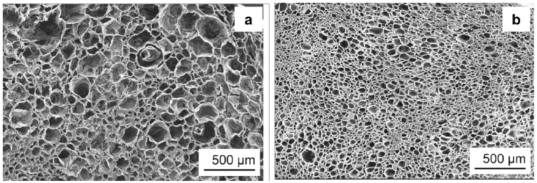
Besides their use as a nucleating agent for polymer crystallization, BTAs were also applied as a nucleating agent for foam cells of i-PP by Mörl et al. [28]. The researchers developed a conceptual approach describing the application of BTAs as a foam cell NA for i-PP in a tandem foam extrusion line, shown in Figure 19. It was reported that in the first region, the BTA/i-PP hybrid compound enters the first extruder and heats up. In the second region, BTAs and CO2 were intimately dissolved and dispersed in an i-PP melt at temperatures up to 240 °C under pressure. In the third region, the melt was cooled down to 160 °C which was the temperature used for foaming. Upon cooling, BTAs self-assembled into nanofibers in the second extruder. These nanofibers featured a corrugated surface as well as a high surface to volume ratio. Both are attributed to provide a large quantity of nucleating sites for foam cell nucleation (Region III). In the fourth region, the rapid pressure drops at the die resulted in foaming of the i-PP. The foamed i-PP was then transferred to the calibration unit where the foam cooled down, cell growth stopped, and the final cell structure was obtained. The authors stated that the BTA nanofibers which are located in the cell walls and struts of the i-PP foams, improved the foam morphology significantly. SEM micrographs of the neat i-PP foam and i-PP with 0.4wt% to-BTA are shown in Figure 20. As depicted in Figure 20a, the neat i-PP exhibits a non-uniform morphology with larger cells. 0.4wt% BTA led to smaller cell sizes with a reduction from 68 to 27μm and a narrower cell size distribution compared to those of the neat i-PP [28].
Figure 17: Charpy impact strength ak for the neat and nucleated materials at room temperature [24]. (Reproduced with permission of Elsevier).
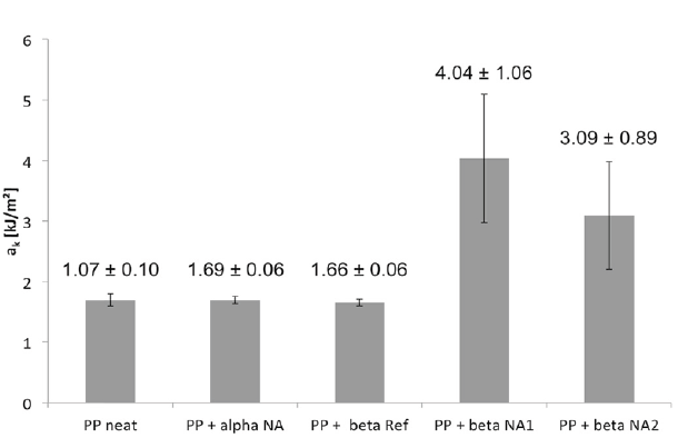
Figure 18: Fatigue crack growth of i-PP + alpha and i-PP + beta NA1 [27]. (Reproduced with permission of Elsevier).

Figure 19: Fatigue crack growth of i-PP + alpha and i-PP + beta NA1 [27]. (Reproduced with permission of Elsevier).
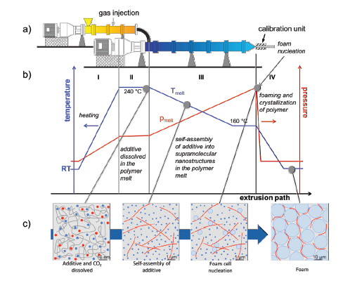
Figure 20: SEM micrographs of the foam extruded (a) neat i-PP and (b) i-PP with 0.4wt% BTA (Modified from) [28]. (Reproduced with permission of SAGE Publications).
Perspective of Engineers
Apart from the perspective of chemists, there is a large variety in describing how the hybrid material is defined from the perspective of engineers. Some of the definitions from the engineer`s view is given as examples:
- Hybrid material is a combination of different metallic materials with several metals: Multi-Metal Design [29].
- Hybrid materials are joints between several components, which belong to different material groups [30].
- Hybrid materials are combinations between metallic-ceramic, ceramic-polymer or polymer-metallic components [30].
- Hybrid material exhibit a multilayer structure with at least two materials of different main material groups, homogeneous in a macroscopic way, but quasi homogeneous or heterogeneous in a microscopic point of view [30].
- Hybrid materials are a combination of different polymers (matrix systems) fiber reinforcements and optionally metallic structures in one composite part [31].
- Hybrid parts: The best of two worlds: Combination of polymer and metal [32].
- Hybrid material is a composite with a combination of two or more fiber materials [33].
- Hybrid materials on different scales offer an extremely broad spectrum of properties that cannot be addressed by any material class alone [34,35].
The definition of hybrid material varies even among engineers having the same point of view. Despite a great confusion in defining a hybrid material, the understanding and application of the hybrid materials in each field (chemistry or engineering) are commonly existing. While the chemists evaluate and define hybrid material which can be composed of organic-organic, inorganic-inorganic or organic-inorganic components on sub-micron scales, engineers define it at micro-, meso- and macro-scales. The first example to an engineering hybrid construction is the hybrid- front end of a Ford Focus (C170) which was developed in 1999. It is the first mass-produced vehicle having a hybrid component. The detailed construction of the hybrid component is illustrated in Figure 21; [36,37]. It was reported that a hybrid construction, manufactured using metal (steel sheet) and polymer (Polyamide (Trade Name: Durethan® BKV30, Bayer AG)) via injection molding, features 40 % weight and 10 to 15 % cost reduction against the front end part composed of only steel [36,37]. The approach of the replacement of metal parts with plastic parts to reduce weight and cost is quite similar with the engineering hybrid construction GLARE® in aircraft industry. After the construction of the hybrid-front end part where Polyamide (PA) (Durethan BKV30, Bayer AG) was used, Bayer AG applied for a patent of “Plate-like lightweight structural elements” [38], shown in Figure 22.
Figure 21: The hybrid-front end construction of the first mass-produced vehicle Ford Focus (C170) (Modified from) [37] . (Reproduced with permission of John Wiley and Sons).
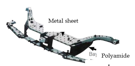
Figure 22: Illustration of plate-like lightweight structural element [38] (Reprinted and edited with permission of Covestro AG. Copyright (2002)).

It is a plate-shaped lightweight component based on a polymer-metal hybrid composite. The lightweight component consists of at least two oppositely arranged plates and intermediate cavities forming support structure made of a thermoplastic material. The metal plates are firmly connected with anchoring points which are evenly distributed on the surface of the metal plates [38].
Moreover, the company Evonik Industries designed a hybrid part, namely “Erlanger Träger” in 2013 to be applied in automotive industry, shown in Figure 23 [39]. The hybrid material is composed of an aluminum sheet and a co-polyamide (VESTAMELT® X1333-P1, Evonik Industrials) served for the technology development of the hybrid components. It was claimed that the hybrid part is a replacement of a load-bearing component used in several Mercedes vehicles. It leads to 20 % weight reduction compared to the conventional technology [39]. Furthermore, Neue Materialien Bayreuth (NMB) GmbH [40] developed a process chain, namely functional oriented composites (FORCE), for industrial-scale production of unidirectional (UD)-Tape thermoplastic hybrid parts. The FORCE process chain is illustrated in Figure 24.
Figure 23: Image of the hybrid part “Erlanger Träger”.(© Evonik, Reference: Evonik Industries AG)

Figure 24: Process chain of the industrial production of function integrated hybrid parts [40]. (Reproduced with permission of Neue Materialien Bayreuth GmbH).

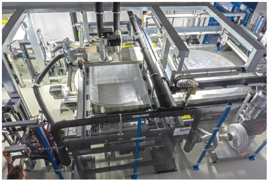
FORCE is a three-step process including FORCE-placement, FORCE-con and FORCE-molding. In the FORCE-placement step, the two-dimensional lay-up of the pre-shaped UD tapes (having suitable length for the FORCE-placement technology) on a fixed table takes place. These tapes are then stacked on a second table using a layer pick-and-place unit. The second table is rotatable leading to achieve a desired angle between the layers. Afterwards, the layers having the desired orientation are fixed via ultrasonic welding. Figure 25 shows the FORCE-placement technology line.
Figure 25: FORCE-placement technology at NMB GmbH [40]. (Reproduced with permission of Neue Materialien Bayreuth GmbH).
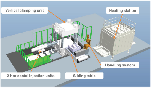
In the second step (FORCE-con), the stacked tape layers are pre-consolidated in a double belt press. FORCE-con has nine different individually controlled temperature zones where the stacked layers can be heated up to 250±5 °C. The conveyer speed ranges between 0.2 and 10m/min which can be adjusted depending on the type of the thermoplastic tape. In the third step (FORCE-molding) (Figure 26), the pre-consolidated stacked layers (preform) are heated above their melting temperature in a convection oven (heating station). The heating station can reach temperatures up to 290±2 °C. The heated layers are then passed to the handling system via a robot gripper system. Afterwards, the layers are transferred to the sliding table where a lower positioned mold slides into the pressing position, molding and consolidating the preform to its final design and shape. Additionally, two horizontal injection units can be applied if some functional elements such as ribs, bosses and snap fit joints are required to be integrated to the preform.
Figure 26: Schematic illustration of FORCE-molding units [40]. (Reproduced with permission of Neue Materialien Bayreuth GmbH).
Kropka et al. [41] used the FORCE technology to produce a hybrid part which is composed of inorganic-organic components in larger than sub-micron scale. Although, the strategy of combining inorganic and organic components is applicable according to the IUPAC definition of hybrid material, the interaction of different components exists at greater scales in engineering hybrid parts. In this study, the researchers used a combination of a PA-carbon fiber UD tape (with a foot print of 30kg CO2/kg, price of 25€/kg (price for 2018) and flexural modulus of 92GPa) and a PA-glass fiber UD tape (with a foot print of 0.9kg CO2/kg, price of 7.5€/kg (price for 2018) and flexural modulus of 31GPa) to obtain economically and ecologically reasonable products. The combination of UD-Tapes of different fiber types was then processed into load-optimized and high-strength hybrid parts via FORCE technology. Furthermore, it was reported that due to the application of MuCell® technology in one of the injection unit utilized in the in FORCE-molding unit, it is possible to fuse manufacture lightweight hybrid prototypes with various shapes like Evonik’s “Erlanger Träger” in a very short cycle time of 60-90 s and a material scrap rate less than 5%.
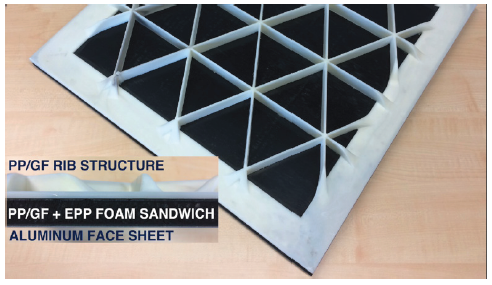
In another study, Kropka et al. [42] obtained a hybrid sandwich part based on a metal sheet, GF-reinforced PP sheet and an expanded-PP (EPP) foam core via FORCE processing chain. The researcher used FORCE-placement step to lay up the preformed PP sheets and obtained UD- GF Tape lay-up. Afterwards, in order to increase the consolidation quality, the surface roughness of aluminum sheets was increased by sandblasting. In the FORCE-con step, the sandwich construction of aluminum (Al) face sheets, preformed PP/GF UD-Tape lay-up and EPP bead foam core with a density of 80kg/m3 were consolidated together. The consolidated hybrid sandwich was then functionalized by applying the isogram PP/GF rib structure via FORCE-molding unit. The functionalized hybrid sandwich part is shown in Figure 27.
Figure 27: Top and side view of the functionalized hybrid sandwich part. The side view exhibits the layered construction of the hybrid part. Layers from top to bottom: PP/GF rib structure, PP/GF sheet, EPP foam core, PP/GF sheet, Al face sheet [42]. (Reproduced with permission of Neue Materialien Bayreuth GmbH).
Conclusion
Hybrid materials have been taking an increasingly significant part in our daily life from Stone Age to nowadays in a large variety of applications. However, the definition of hybrid materials differs very much among the disciplines, for instance, chemistry, biology, physics and engineering. In this work, we attempted to give an interdisciplinary overview to hybrid materials transferring the view from chemistry to the applied engineering science by focusing on different definitions and examples. Through the approach of chemists and the corresponding IUPAC definition, hybrid materials were described as a combination of inorganic and organic, inorganic and inorganic or organic and organic components in scales of less than 1μm. Firstly, PPE/SAN blends compatibilized with SBM and JPs as well as PPE/SAN blend foams nucleated by JPs, secondly, PS/PMMA blends compatibilized with hybrid K-JPs were given as examples following the definition of a hybrid material by chemist’s perspective. Furthermore, the SPA-based i-PP and the BTA nucleated i-PP foam were also defined as hybrid materials from a point of chemists. In contrast to the chemists` approach, engineers defined hybrid materials as combination of different materials such as, metal and polymer, at meso- and macro-scales. GLARE® for aircraft industry, hybrid-front end construction of Ford Focus (C170), Erlanger Träger and hybrid parts produced by FORCE technology for automotive industry were presented as examples according to the engineers´ approach. Consequently, an important aim of future research will be to develop hybrid materials further with enhanced properties for various applications. Clearly, the definition of hybrid materials in other disciplines also needs to be improved, to compare and develop precise definitions for each specific discipline with the purpose of avoiding confusion.
References
- Stone age weapons: Arrows & spears.
- Wanhill RJH (2017) Glare®: A versatile fibre metal laminate (FML) concept. In: Prasad NE, Wanhill RJH (Eds.), Aerospace materials and material technologies (1), Springer, Singapore, pp. 291-307.
- Yaroshevich A, Kaufman D, Bar YO, Mina W, Dmitri N, et al. (2018) Design and performance of microlith implemented projectiles during the middle and the late epi paleolithic of the levant: Experimental and archaeological evidence. Journal of Archaeological Science 37(2): 368-388.
- Microlith technology.
- Deom JM, Sala R, Laudisoit A (2019) The ili river delta: Holocene hydrogeological evolution and human colonization. Socio-Environmental Dynamics along the Historical Silk Road, pp. 67-94.
- The mystery of Maya blue finally solved.
- Vogelesang LB, Roebroeks GJ, Joannes H (1987) Laminate of metal sheets and continuous glass filaments-reinforced synthetic material.
- Rans C (2011) Bolted joints in glass reinforced Aluminium (Glare) and other hybrid fibre metal laminates (FML). In: Camanho P, Tong L (Eds.), Composite joints and connections. Woodhead Publishing, Sawston, UK, pp. 35-76.
- Vermeeren CAJR (2003) An historic overview of the development of fibre metal laminates. Applied Composite Materials 10: 189-205.
- Nardi D, Abouhamzeh M, Leonard R, Sinke J (2018) Detection and evaluation of pre-preg gaps and overlaps in glare laminates. Applied Composite Materials 25(6): 1491-1507.
- Fokker to automate FML production.
- Stand-Up resealable pouches.
- Makishima A (2004) Possibility of hybrid materials. Ceramics Japan 39: 90-91.
- Chadwick AV, He J, Hess M, Horie K, Jones RG, et al. (2007) Definitions of terms relating to the structure and processing of sols, gels, networks, and inorganic-organic hybrid materials. Pure and Applied Chemistry 79(10): 1801-1829.
- Auschra C, Stadler R (1993) Polymer alloys based on poly (2,6-dimethyl-1,4-phenylene ether) and poly(styrene-co-acrylonitrile) using poly(styrene-b-(ethylene-co-butylene)-b-methyl methacrylate) triblock copolymers as compatibilizers. Macromolecules 26: 6364-6377.
- Gottschalk A, Mühlbach K, Seitz F, Stadler R, Auschra C, et al. (1994) Blends of poly (2,6–dimethyl–1,4–phenylene oxide) with styrene copolymers. Macromol Symp 83(1): 127-146.
- Ruckdaeschel H, Sandler JKW, Altstaedt V, Schlaz H, Abetz V, et al. (2007) Toughening of immiscible PPE /SAN blends by triblock terpolymers. Polymer 48(9): 2700-2719.
- Auschra C, Stadler R, Chemie O, Becherweg JJ (1993) New ordered morphologies in ABC triblock copolymers. Macromolecules 26(9): 2171-2174.
- Bahrami R, Loebning TI, Schmalz H, Mueller AHE, Altstaedt V, et al. (2014) The impact of janus nanoparticles on the compatibilization of immiscible polymer blends under technologically relevant conditions. ACS Nano 8(10): 10048-10056.
- Bahrami R, Loebning TI, Schmalz H, Müller AHE (2017) Synergistic effects of janus particles and triblock terpolymers on toughness of immiscible polymer blends. Polymer 109: 229-237.
- Hertzberg RW, Manson JA (1980) Fatigue of engineering plastic. Academic Press, New York, USA.
- Baerwinkel S, Bahrami R, Loebning TI, Schmalz H, Mueller AHE, et al. (2016) Polymer foams made of immiscible polymer blends compatibilized by janus particles effect of compatibilization on foam morphology. Adv Eng Mater 18(5): 81-825.
- Weiss S, Hirsemann D, Biersack B, Ziadeh M, Mueller AHE, et al. (2013) Hybrid Janus particles based on polymer-modified kaolinite. Polymer 54(4): 1388-1396.
- Kersch M, Schmidt HW, Altstädt V (2016) Influence of different beta-nucleating agents on the morphology of isotactic polypropylene and their toughening effectiveness. Polymer 98: 320-326.
- Mohmeyer N, Muller B, Behrendt N, Hillenbrand J, Klaiber M, et al. (2004) Nucleation of isotactic polypropylene by triphenylamine-based trisamide derivatives and their influence on charge-storage properties. Polymer 45(19): 6655-6663.
- Mörl M (2018) Increasing the toughness of isotactic polypropylene by controlling the morphology using 1,3,5-benzenetrisamides, University of Bayreuth, Bayreuth, Germany.
- Kersch M, Pischke L, Schmidt H, Altstädt V (2014) Influence of trisamide-based additives on the morphological and mechanical properties of isotactic polypropylene. Polymer 55(15): 3227-3233.
- Mörl M, Steinlein C, Kreger K, Schmidt HW, Altstädt V, et al. (2018) Improved compression properties of polypropylene extrusion foams by supramolecular additives. J Cell Plast 54(3): 483-498.
- (2018) Hybrid Materials and Structures. International Conference.
- Zeilinger H (1985) Composite and hybrid materials - Definition, composition, application. In Proceedings of the design with composite and hybrid materials, pp. 1-11.
- Stokes GCM, Kollmannsberger A, Ehard S, Compston P, Drechsler K (2018) Manufacture of steel–CF/PA6 hybrids in a laser tape placement process: Effect of first-ply placement rate on thermal history and lap shear strength. Compos Part A: Appl Sci Manuf 111: 42-53.
- (2018) Hybrid parts.
- Handbook fiber composites/composites: Basic Processing applications. (4th edn), Springer Vieweg, New York, USA.
- SchlarbA K (2013) Engineering science annual magazine. Plastics Technology pp. 10-13.
- Ehrenstein PGW, Amesöder S, Díaz LF (2003) Material and process optimized production of flat plastic and initiation and motivation.
- Koch B, Knözinger G, Pleschke T, Wolf HJ (1999) Plastic magazine. Munich, Germany, pp. 83-89.
- Bassan D (2013) Hybrid design approaches. In: Lehmhus D (Ed.) Structural materials and processes in transportation 1. pp. 499-516.
- Wagenblast J (2002) Plate-shaped lightweight component. European Patent EP1 223 032 A2.
- (2013) Evonik and the lightweight aluminum-plastic hybrid go into series production, Evonik Degussa GmbH, Kunststoff Magazine.
- Kropka M, Selveraj K, Neumeyer T, Altstaedt V (2019) Process chain for industrial-scale production of UD-Tape based thermo- plastic composite products.
- Kropka M, Muehlbacher M, Neumeyer T, Altstaedt V (2017) From UD-tape to final part- A comprehensive approach towards thermoplastic composites. Procedia CIRP 66: 96-100.
- Altstaedt V (2019) Hybrid materials- Historical perspective and current trends. In Proceedings of the Eurofillers Polymer blends, Palermo, Italy.
© 2020 Volker Altstädt. This is an open access article distributed under the terms of the Creative Commons Attribution License , which permits unrestricted use, distribution, and build upon your work non-commercially.
 a Creative Commons Attribution 4.0 International License. Based on a work at www.crimsonpublishers.com.
Best viewed in


.jpg)


 Editorial Board Registrations
 Submit your Article
 Refer a Friend
 Advertise With Us
.jpg)


.jpg)


.bmp)
.jpg)
.png)
.jpg)


.jpg)


.png)

.png)


.png)


