- Submissions

Full Text
COJ Electronics & Communications
Brushless Direct Current Motor Design and Analysis
Mustafa Yaz and Emrah Cetin*
Yozgat Bozok University, Engineering and Architecture Faculty, Turkey
*Corresponding author: Emrah Cetin, Yozgat Bozok University, Engineering and Architecture Faculty, Electrical and Electronics Engineering, Turkey
Submission: August 17, 2021;Published: September 29, 2021

ISSN 2640-9739Volume2 Issue2
Abstract
Direct current motors are machines that convert direct current electrical energy into mechanical energy. It is based on the principle of moving with the effect of the magnetic force that occurs in the opposite direction to the permanent magnets in the motor when electric current is applied to the windings inside the motor. Special driver circuits called ESC are used for their operation. It is used in applications where high performance is required thanks to its advantages, low friction, very high efficiency and no wearing parts such as brushes. The disadvantages are that it has to be driven by the driver. Electric vehicles, electrical appliances etc. in this study. It is about the design of the Brushless Direct Current Motor (BLDC), which is frequently used in the fields, and the analysis of the designed system. Brushless direct current motor was designed and implemented, and analysis of brushless direct current motor was made. General features of BLDC motor; the supply voltage is 72 volts, the number of slots is 45, the number of poles is 50, and the windings are star-connected. The analysis of the engine was created to estimate the performance of the engine and generator accurately and completely to be designed, and the design software was made with Motor Solve BLDC. Due to the analysis results, the designed motor is convenient for the production. There are pure-like back EMF, ignorable cogging torque and enough flux linkage to produce torque. Also, three starting angle is researched for the starting torque. Maximum torque is obtained at the 90 degree shift of the magnet angle.
Keywords: DC motor; Motor design; Motor analysis; BLDC Motor
Introduction
With the developing technology, the number of high-performance products that make
human life easier is increasing day by day. With the increasing smart technology, integrated
products arising from the machinery and electronics sector are also revealed. One of them
is a brushless Direct Current (DC) motor. Brushless Direct Current (DC) motors are widely
used today in most industrial applications, especially in the automotive industry, space
technologies, computer technologies, medical electronics, military fields, robotic applications,
and household products. These motors have high torque/current and a high torque/inertia
ratio. Also, brushless DC motors have advantages such as robust construction, high efficiency,
and high reliability The axial flux permanent magnet brushless dc motor, which is a permanent
magnet motor class that has dominated the field of electrical machines in recent years, has
many advantages over other motor types. Since the rotor losses are not excited, their efficiency
is higher [1,2]. Electric motors are used to convert electrical energy into motion energy.
Linear motion is needed at many stages of industrial production facilities. On the other hand,
many additional parts such as reducer, belt, and pulley are needed to obtain linear motion
from electric motors that produce circular motion. This not only makes location control more
difficult but also increases the cost and maintenance requirement. It also leads to a decrease
in reliability and efficiency. Instead of these existing solutions, the use of linear motors,
which are rapidly becoming widespread and produce linear motion directly, which are more
reliable, will eliminate these drawbacks. The use of linear motors has become widespread in
recent years to obtain linear motion. Linear DC motors are encountered in many areas from
small-scale applications to transportation and missile launch systems. Linear electric motors
can be collected in two groups as AC and DC. Due to their nonlinear nature, AC motors require
advanced control techniques, high-capacity microcontrollers, and complex electronic circuits.
DC motors are more advantageous in this respect [3].
The invention of electric motors, an electromechanical device that converts electrical
energy into mechanical energy, is one of the biggest locomotives in technology and engineering. Faraday took the first step towards direct current machines when
he discovered that a conductor with current flowing through it is
repelled by the magnetic field. There is no difference between the
first DC machines and the machines used today, in terms of structure
and operating principle, and the working logic of all of them is the
same. In DC motors, collectors are used to transmitting the voltage
to be applied to the armature, and brushes are used to transmit the
current in the outer circuit to the armature. However, since there
are no collectors and brushes in Brushless Direct Current Motors
(BLDC), the commutation is made electronically. The BLDC motor
is operated by the method of energizing the stator windings in the
appropriate order according to the position information of the rotor
received from the sensors. The absence of collectors and brushes in
the structure of direct current motors in BLDC motors has made
them advantageous with less maintenance and breakdowns. At the
same time, they have a longer life than direct current motors, they
have very little heating, silent operation, no friction, and no arc.
Permanent magnets are used in the rotors of BLDC motors. With the
reduction in the cost of the magnets used here and the development
of the switching elements used in power electronics, BLDC motors
have found more application areas for themselves. These Electric
vehicles, Electrical appliances, Hard disk, CD-ROM engines, Robot
industry, Automobile throttle, Oil and fuel pumps areas such as [4].
Literature Summary
Ehsani M et al. (2003) [5] analyzed the effects of induction
motors, brushless direct current motors, and switched reluctance
motors on vehicle performance for an electric and hybrid electric
vehicle. As a result of the analysis, it has been reported that the
permanent magnet direct current motor has the highest torque
compared to the other motors. Jiaxin C et al. (2006) [6] analyzed
parameters such as air-gap flux, opposing electromotive force, and
inductance of a brushless direct current motor using magnetic
Field Finite Element Analysis (FEA). Ertuğrul N et al. (1994) [7]
stated that the rotor position information can be obtained without
using a sensor with the voltage and current signals received from
a brushless direct current motor. Singh (1997) [8] investigated the
effects of permanent magnet brushless direct current motors on the
reduction of torque ripple, semiconductor power electronics, and
microcontrollers on cost reduction and possible future applications.
Zhang J et al. (2010) [9] calculated the cogging torque of the
stator internal permanent magnet machine using Finite Element
Analysis (FEA). Karakulak O et al. (2012) [10] designed the driver
circuit of a brushless DC motor operating at a constant speed and
load with the PIC16F877 microcontroller and circuit components
that are widely available and affordable in the market [10]. Bektaş
Y et al. (2011) [11] made a comparison between the Matlab®/
Simulink® program of the brushless direct current motor and
the Hysteresis Band Control and PWM control method in terms
of torque, speed, and position. They emphasized the positive and
negative aspects of both methods. Hasanusta K et al. (2015) [12]
investigated the effect of the change of sensor positions on the
parameters of BLDC in the case of motor-loaded operation of the
hall sensor position, which is between 600 and 1200 in brushless
direct current motors. Wu Q et al. (2012) [13] created the source
code for the dsPIC30F4012 microcontroller used in the control of
the brushless direct current motor and the necessary hardware
circuit was designed [14].
Materials and Methods
Structure of brushless direct current motors
Brushless Direct Current Motors (BLDC) is a relatively
new motor that is increasingly used in areas such as electrical
appliances, automotive, and aviation, with both decreasing costs
and functionality. In Figure 1, the section views of the hall sensor
positioned on the shaft, the magnet which is the inner rotor, and the
stator windings are given. The change of direction of the current in
a coil in the armature of a DC motor with the help of collector slices
and brushes is called commutation [15].
Since BLDC motors do not have collectors and brushes, the
commutation is made electronically. The brushless type of DC
motor arrangement where the electronic driver uses the position
information received from the rotor by the sensors to energize the
stator windings in the appropriate order is shown in Figure 2.
Figure 1: Brushless type DC motor section view.

Figure 2: Brushless type DC motor layout.

Stator
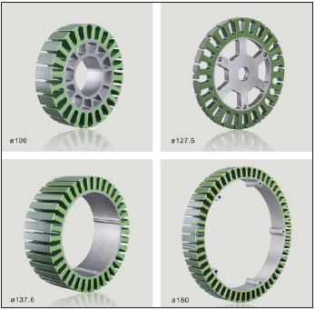
The stator is the fixed part of the electric motor and consists of sheet cores, where the windings are wound, and the magnetic conductor losses are minimum thanks to the silicon it contains. Sheet cores are cut and pressed after the molds in the desired number of grooves are determined. Powder coating or plastic insulators are used to prevent the windings from contacting the stator and short circuit. Windings are prepared by connecting, varnishing, and pulling out the end cables with connectors. In Figure 3, different stator inner and outer diameter, mold type, number of slots, etc. used in brushless direct current motors. Stators with properties are seen [16].
Figure 3: BLDC motor stator [14].
Rotor
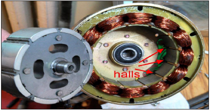
The rotor of the BLDC motor consists of magnets. It is possible to design BLDC motors in two ways as the inner rotor (In runner) and outer rotor (Outrunner). In the outer rotor design, the permanent magnets are wrapped around the stator windings, in the inner rotor design, the stator windings are the permanent magnets. Permanent magnets are used to create magnetic fields without any magnetomotive force. Advances in magnet technology have left the place of ceramic magnets, which were used until about 30 years ago, to Neodymium-Iron-Boron (NdFeB), often known as Neodymium magnets. The higher the number of magnet poles in the rotor, which directly affects the speed and torque value of the motor, the higher the torque but the lower the speed. Figure 4&5 show 14 pole outer rotor and 8 poles inner rotor BLDC motors, respectively
Figure 4: Brushless type DC motor (outer rotor and stator).

Figure 5: Brushless type DC motor (inner rotor and stator).
Working principle of brushless direct current motors
John Ambrose Fleming created the left-hand rule, a simple method for studying the direction of movement of an electric motor. Left-hand rule; The repulsion direction of the conductor in the magnetic field changes depending on the direction of the magnetic field and the direction of the current passing through the conductor. The rotation principle of a direct current motor is shown in figure 6.
Figure 6: DC motor rotation principle [15].
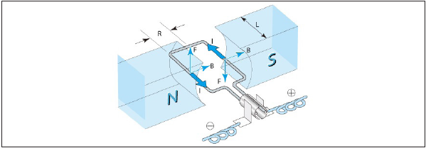
When a current-carrying conductor is placed in the magnetic
field, the conductor is exposed to a mechanical force and is pushed
out of the magnetic field. The magnitude of this force is:
F=B.L.I [1]. It is found by the equation.
Here;
F=Force (N) B=Magnetic flux density (T)
I=Current (A) L=Length of cable in magnetic field (m)
The current changing direction with the help of the collector and
brushes on the DC motor will keep the motor rotating continuously.
If the brushes are in constant contact with the collector, it will cause
the heat in the motor to increase, sparks and carbon dust to form.
BLDC motors removed the collectors and brushes from the
motor body, which caused the disadvantage of brushed DC motors.
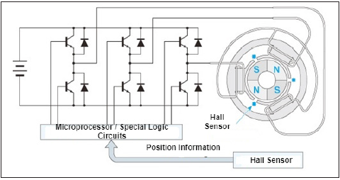
BLDC motors consisting of stator and rotor as in other motors consist of stator (fixed part) coil and rotor (rotating part) magnets. The general operating principle is that after the magnetic field interaction between the stator coils and the rotor magnets, the torque to rotate the motor is formed. However, for the continuity of this rotation torque, the magnetic field in the stator must also rotate. In the control of the rotation of the magnetic field, position information is sent to the microprocessor by hall sensors. After the position information received from the Hall sensors is processed in the microprocessor, the basic operating principle, which is that the switching elements in the power circuit are triggered in the appropriate order and create a permanent rotating magnetic field in the stator windings connected to the star is visualized in Figure 7.
Figure 7: BLDC motor basic operating principle.
Analysis of the Referenced BLDC Motor with Motor solve BLDC Module
Motor Solve BLDC is the design software created to predict the performance of the engine and generator accurately and completely to be designed. With the 14-day trial version of the Motor Solve cloud-based trial virtual lab, the reference engine was analyzed.
Motor solve BLDC software
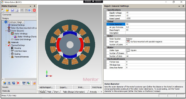
When the software is started, the general settings of the machine to be designed, rotor and stator design, stator winding values, rotor magnet material, and motor outer body dimensions are entered in the screen in Figure 8.
Figure 8: Motor solve BLDC software overview.
Specifying engine general settings in software
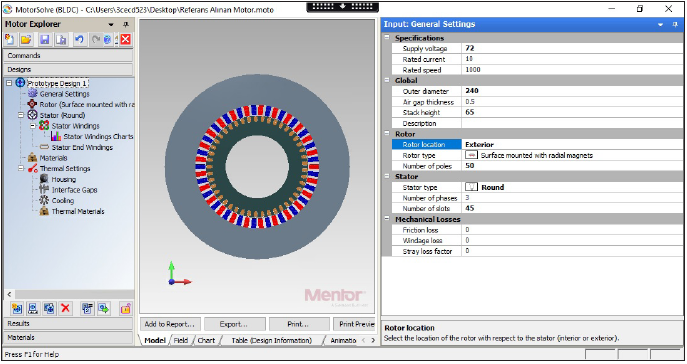
The appropriate supply voltage, rotor location-type, and pole number, stator type-phase number, and groove number values of the referenced motor were entered into the software and the model shown in Figure 9 was created.
Figure 9: Motor solve BLDC general settings.
Specifying rotor design settings in the software
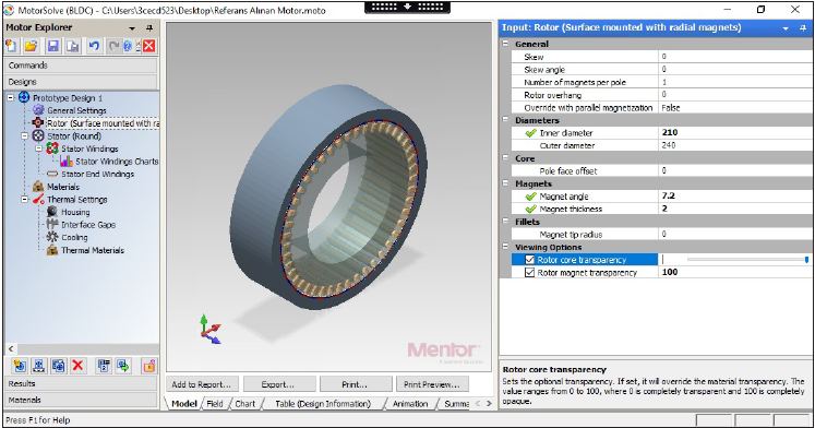
The appropriate rotor inner-outer diameter, magnet angle, and thickness values of the referenced motor have been entered into the software and the model shown in Figure 10 has been created.
Figure 10: Motor solve BLDC rotor design settings.
Specifying stator design settings in software
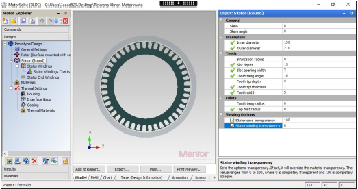
The appropriate stator inner-outer diameter, hollow depthwidth, thread angle-thickness, and width values of the referenced motor have been entered into the software and the model given in Figure 11 has been created.
Figure 11: Motor solve BLDC stator design settings.
Specification of stator winding values in software
The connection type of the phases in the stator windings is a star and the coils of the phases are connected in series. Motor Solve BLDC software automatically calculates the winding resistance and inductance values, and these values are respectively; is 0.1291Ω and 105.5μH (Figure 12-15).
Figure 12: Motor solve BLDC motor winding arrangement.
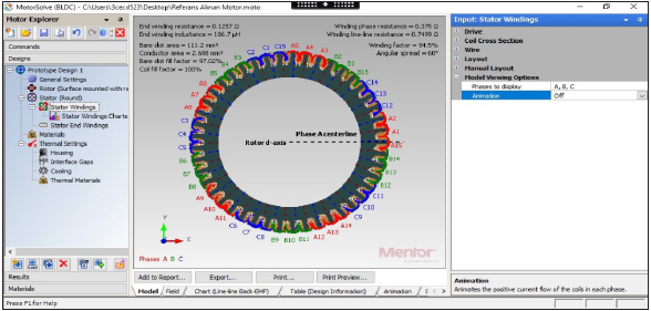
Figure 13: Stator XY view after motor solve BLDC motor winding arrangement.

Figure 14: Stator XYZ view after motor solve BLDC motor winding arrangement.
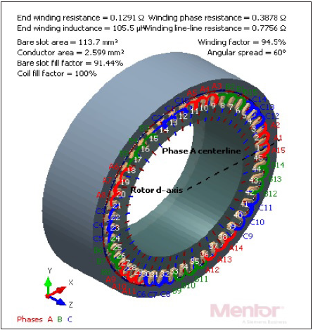
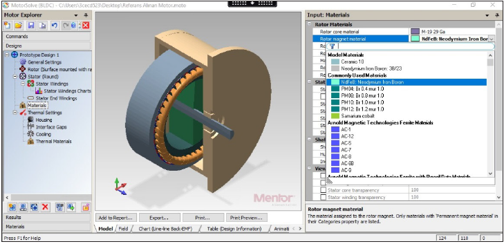
Figure 15: Motor solve BLDC magnet material selection setting.
Selecting rotor magnet material in software
The Neodymium-Iron-Boron (NdFeB) magnet on the motor rotor referred to is selected in the software.
Specifying outside body design values in the software
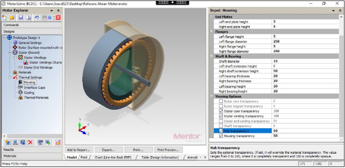
The appropriate values and the values of the outer body of the referenced engine are specified in the software and the model with images in Figure 16 has been created.
Figure 16: Motor solve BLDC outer body design settings.
Direct Current Motor Analysis
Cogging torque
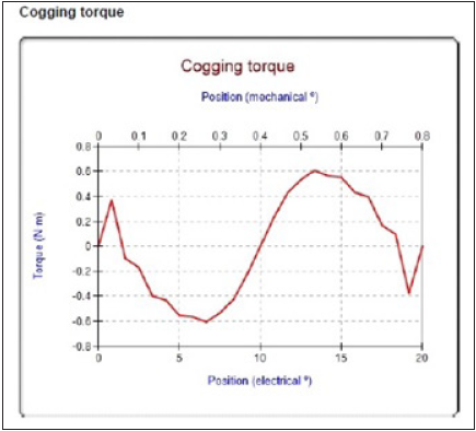
Cogging Torque (gear torque), which is the most important disadvantage of BLDC motors, is called the change in torque in the rotor as a result of the interaction of magnet flux and stator teeth. When the rotor of an unenergized BLDC motor is rotated by hand, we feel the rotor jumping from one point to another. The torque generated in these jumps is the torque required to break from the current rotor/stator alignment and move on to the next rotor/ stator alignment. This torque is usually filtered by the inertia of the system at high speeds, but it will create an undesirable situation as it causes fluctuation of the output torque especially at low speeds. When the graph in Figure 17 is examined, it is seen that the gear torque value is maximum ±0.6N.m. in the 22N.m. continuous torque. Thus, 2.7% of the electromagnetic torque is cogging torque which is very convenient as in the literature.
Figure 17: Electrical/mechanical angle-gear torque graph of the referenced motor.
Air gap flux
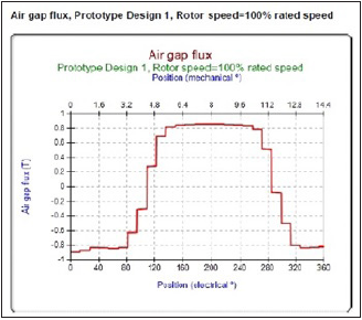
Since the air gap required to separate the rotating rotor from the stator creates a high resistance against the magnetic flux in the magnetic circuit, these gaps cause unwanted increases in magnetization current and related electrical loss. This inevitable situation should be as small as possible to reduce the requirement for magnetizing power, but the manufacturing tolerances should be large enough to prevent stator and rotor contact against mechanical deflection and looseness. When the graph in Figure 18 is examined, it is seen that the electrical angle position values of the air gap flux value are 0.8 Tesla in the range of 1200-2800.
Figure 18: Electrical/mechanical angle-air gap flux graph of the referenced engine.
Surface force density (N/mm2)
The arrow graph of the surface force density of the BLDC motor taken as reference in Figure 19 is shown.
Flux density
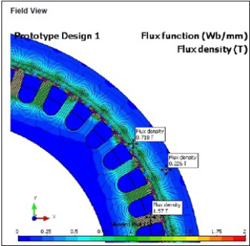
The amount of flux passing through a unit area perpendicular to the magnetic field is called flux density and is an important quantity used in electrical machine design calculations. It is denoted by the letter B and its unit is Tesla(T). Motor Solve BLDC software Figure 5&20 shows the values of the flux density distribution at some points. As seen the transpositions of the electromagnetic waves, there is an affordable result for the non-heating.
Figure 19: Surface force density arrow graph.
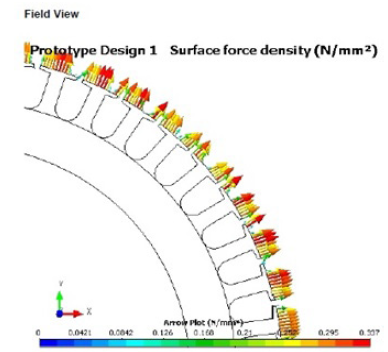
Figure 20: Flux density graph of the referenced motor.
Back electromotive force (Back EMF)
The windings of an electric motor act like a generator when cutting magnetic field lines. A potential is produced in the windings, which is measured in volts and called the Electromotive Force (EMF). According to Lenz’s law, this EMF causes a secondary magnetic field that opposes the original change in magnetic flux that causes the motor to rotate. In simpler terms, the EMF resists the natural motion of the motor and is called the “back” EMF. BLDC motor manufacturers specify a parameter known as the backing EMF constant that can be used to estimate the EMF for a given speed. The potential in a winding can be calculated by subtracting the back EMF value from the supply voltage. The motors are designed in such a way that the potential difference between the back EMF and the supply voltage causes the motor to draw the rated current and deliver the rated torque when operating at rated speed. Driving the motor beyond the rated speed significantly increases the back EMF, decreases the potential difference between the windings, and then decreases the current and lowers the torque.
Sensor less BLDC motor control has one major drawback; When the motor is stationary, no EMF is generated that informs the MCU about the stator and rotor position. The solution is to start the motor in an open-loop configuration by energizing the coils in a predetermined order. Although it is not possible to run the engine efficiently, it will start to rotate. Eventually, the speed will be sufficient to generate enough backing EMF for the control system to switch to normal (and efficient) closed-loop operation. Because the back EMF is proportional to the rotational speed, sensor less BLDC motors may not be a good option in applications that require very low speeds. (Figure 5&21) shows that the peak values of the back electromotive force are ±400 Volts.
Torque-rotor speed (Torque-Rotor Speed)
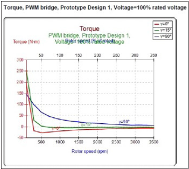
The torque characteristics of the BLDC motor are a very important factor in the design of the BLDC motor drive system. In the graph in Figure 5&22, it is seen that the torque value of the engine is high at low speeds. Three different angle of the magnet starting point is discussed in this simulation. The best starting angle is 90 degree as seen in the figure 22.
Figure 21: Referenced motor back EMF graph.
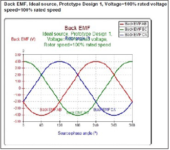
Figure 22: Torque-rotor speed graph of the referenced motor.
Conclusion
Electrical machines are used to generate electrical energy in power stations and to perform mechanical work in the industry. The brushless direct current motor, which has a special place in electric motors, has become the most preferred motor type due to high efficiency and high torque in the low-speed range in recent years when the popularity of electric vehicles has increased continuously. In this study, a brushless direct current motor was designed, and the analysis of the designed motor was carried out with different parameters. Analysis of a brushless direct current motor used in electric bicycles was performed with Motor Solve BLDC software.
Electromagnetic and transient analysis have been done. The cogging torque of the designed motor is 0.6N.m. in the 22N.m. continuous torque. This makes 2.7% in total amount. Air gap flux density is 0.8T between the surface of the magnets and the stator. This is an appropriate condition for the torque production. Also, three different starting angle is discussed. The best of the starting angle is observed as 90 degree as given in the figure 22. As a result, a more affordable motor has been created in contrast to the studies.
Acknowledgment
This study Yozgat Bozok University Scientific Research Projects Unit (MMF-66026/18-174) has been supported by. We thank the institution for their support.
References
- Kayabaşı S, Topçu E (2019) Investigation of the effects of design parameters of miniature brushless dc motors used in industrial applications on motor performance. Al-Jazari Journal of Science and Engineering 6(2): 236-250.
- Aydoğdu Ö, Bayer M (2008) PIC based brushless DC motor driver design. Department of Electrical and Electronics Engineering Selcuk University, Turkey.
- Gödekoğlu H (2007) Brushless DC motor position controller design. Doctoral dissertation, Institute of Science and Technology, Turkey.
- Karakulak O, Yaz O, Eram K, Sabri B, Candan C, et al. (2012) PIC based brushless DC motor driver design. 3rd National Design, Manufacturing and Analysis Congress pp. 231-239.
- Ehsani M, Gao Y, Gay S (2003) Characterization of electric motor drives for traction applications. Industrial Electronics Society, IECON’03, The 29th Annual Conference of the IEEE, Montreal pp. 891-896.
- Jiaxin C, Youguang G, Jiangou Z (2006) Design and performance simulation of a high speed brushless DC motor for embroidery machine application. Technology and Innovation Conference pp. 777-781.
- Ertugrul N, Acarnley P (1994) A new algorithm for sensor less operation of permanent magnet motors. IEEE Trans on Inds App 30(1): 126-133.
- Sıngh B (1997) Recent advances in permanent magnet brushless DC motors. Academy Proceedings in Engineering Sciences 22(6): 837-353.
- Zhang J, Cheng M, Hua W (2010) Calculation of cogging torque for stator interior permanent magnet machine. 14th Biennial IEEE Conference on Electromagnetic Field Computation CEFC'10, Chicago, USA.
- Karakulak O, Yaz O (2012) PIC based brushless DC motor driver design. 3rd National Design, Manufacturing and Analysis Congress pp. 231-239.
- Bektaş Y, Serteller N (2011) Brushless direct current motor (FSDAM) and driver circuit training set analysis development and analysis of the motor in computer environment. Institute of Natural and Applied Sciences pp. 188.
- Hasanusta K, Serteller N (2015) Investigation of optimal hall sensor location in brushless direct current motors (FSDAM) and its effect on motor. Journal of Science 15(1-7): 1-7.
- Wu Q, Tıan W (2012) Design of permanent magnet brushless DA motor control system based on dsPIC30F4012. Procedia Engineering 29: 4223-4227.
- Norouzi P (2015) High performance position control of brushless linear DC motor. Doctoral dissertation, Institute of Science and Technology pp. 1-96.
- https://www.tradekorea.com/product/detail/P658475/silicon-steel-stamping---lamination-bldc-motor-stator--core.html
- https://www.nidec.com/en/technology/motor/basic/
© 2020 Emrah Cetin. This is an open access article distributed under the terms of the Creative Commons Attribution License , which permits unrestricted use, distribution, and build upon your work non-commercially.
 a Creative Commons Attribution 4.0 International License. Based on a work at www.crimsonpublishers.com.
Best viewed in


.jpg)


 Editorial Board Registrations
 Submit your Article
 Refer a Friend
 Advertise With Us
.jpg)


.jpg)


.bmp)
.jpg)
.png)
.jpg)


.jpg)


.png)

.png)


.png)


