- Submissions

Full Text
Aspects in Mining & Mineral Science
Assessment of the Various Slope Stabilization Initiatives Undertaken along the Pathways of Shri Mata Vaishno Deviji Shrine, Jammu and Kashmir Himalaya, India
Naithani AK1* and Nawani PC2
1National Institute of Rock Mechanics, India
2Member Governing Body, National Institute of Rock Mechanics, India
*Corresponding author:A K Naithani, National Institute of Rock Mechanics, Bengaluru - 560 070, India
Submission: August 17, 2023: Published: September 05, 2023

ISSN 2578-0255Volume11 Issue5
Abstract
Twenty-four numbers of potential landslide prone areas have been identified both along the old and new pathways of Shri Mata Vaishno Deviji shrine which injuring the pilgrims. All the landslides and shooting stone areas will be treated in a phased manner. In Phase-I, at five locations slopes protection measures were taken and dismantled Durga Bhawan slope area was also treated after proper investigations. In this paper, slope stabilization measure initiatives at five locations and at dismantled Durga Bhawan slope area are discussed. This study will be very helpful for the replication of the same in similar type of terrain condition across the Himalayan terrain and other part of the country.
Keywords:Landslide; Shooting stone; Cable anchor; Rolled cable net; Rockfall barrier
Introduction
The Holy Shrine of Shri Mata Vaishno Deviji is one of the most popular and revered pilgrimages in the Country, being visited by thousands of pilgrims every day round the year. The Shrine is located at an altitude of 1765m in the Reasi District of Jammu and Kashmir Himalaya and is approachable by road up to Katra town and further by walk over a distance of about 13.5km through the moderate to steep hills along the pathways. Initially one pathway was there to cater to the needs of the pilgrims. The old pathway takes off from Banganga passes through Indraprasth, Ardhkuwari and Sanjhi Chhat ultimately to Bhawan. Later, one more pathway was introduced from Ardhkuwari following a different route up to Bhawan. From Indraprasth (El. 1430m), the old pathway passes through high hills up to El. 1850m to the north of Sanjhi Chhat and then go down to El. 1760m near Bhawan area. In order to avoid ups and downs on the route, a new pathway was made from Indraprasth onwards. It follows a consistent and gradual gradient until it joins the old pathway about a kilometre before the Bhawan. Some portions of these tracks experience landslides and also shooting stones originating from uphill slopes injuring the Yatris.
Shri Mata Vaishno Devi Shrine Board (SMVDSB) was set up as an Autonomous Organisation with the objectives to provide for better management, administration and governance of Shri Mata Vaishno Devi Shrine including maintenance of tracks. Twenty-four potential landslide/shooting stone prone areas have been identified by the SMVDSB Engineers with the help of National Institute of Rock Mechanics (NIRM) in 2010 both along old and new pathways. Topographical survey for 24 slide prone locations has been carried out by IIT Kanpur while geological investigations were conducted by IIT Roorkee. In phase-I, landslide/shooting stone locations 3, 7, 14, 16 and 17 were taken for the protection measures which exhibit global instability problems. Design of protection/support measures of five problematic landslide/shooting stone areas was carried out by THDC India Limited and IIT Roorkee and execution was done under the guidance of NIRM and THDCIL [1]. The cost of the protection measures for five landslide/shooting stones and dismantled Durga Bhawan slope areas, treated in Phase-I was around 18.05 crores and 5.78 crores respectively.
Geology of the Area and Around
The rocks exposed in and around Bhawan area consists of Jammu limestone, which have been brought in juxtaposition with Siwalik Group of rocks on the southern side. The Precambrian Jammu limestone had been affected by post-tectonic activities, leading to formation of a number of joints, folds, small scale faults, shear zones and other such structures. This limestone has a special significance as older (Precambrian) limestones are surrounded by younger rocks forming a tectonic structure called Inlier which is locally called as Riasi Inlier [2,3]. They have a faulted contact with Siwalik rocks on the south and have a sharp angular unconformity with overlaying Subathu Formation on the northern side. The Siwalik Group of rocks is exposed on the southern side of the Jammu limestones with a faulted contact, which is generally concealed below the debris. The Siwalik Group of rocks consist of various types of sandstones, claystones and siltstones, which have been classified into Lower, Middle and Upper Siwalik Formations. These rocks are exposed in Katra and further south. To the north of Katra, Jammu limestones are exposed with a faulted contact.
The major part of Jammu limestones comprises massive to well jointed, bluish grey to dirty grey coloured and thickly bedded microcrystalline limestones and dolomites with clearly developed compositional banding at places. Elephant skin weathering characteristic of limestone terrain is rarely seen at places. Though the limestones seem to have a considerable thickness, the base is not clearly exposed due to the presence of Siwalik rocks seen on the southern side with a faulted contact. The rocks are seen weathered close to the surface, and it extends for a depth of 1 to 3m. The rocks often show small scale secondary calcareous injections due to secondary remobilization. Though rocks are generally exposed on steep to very steep rock slopes, debris are commonly seen on moderate to gentle hill slopes. Debris can be seen on steep slopes also at places but with thin cover. The bedding plane S1 is a major structural discontinuity in Jammu limestones in addition to joints, shear zones and other structural elements. Small scale folds are reported at many places within limestone in the study area. Two sets of joints are clearly seen in many places in the rocks. However, in case of Jammu limestones, the secondary cementation due to circulation of ground water had resulted in cementing the annular space between the joints. Secondary cementation is a major reason for preventing to great extent large-scale instability of the rock slopes, which are traversed by closely spaced discontinuities at places. In fact, the secondary cementation along the discontinuities had helped to increase the shear strength along the planes of separation [4].
Protection Work of Landslides/Shooting Stones and Dismantled Durga Bhawan
In Phase-I at five locations, landslides/shooting stone areas and dismantled Durga Bhawan landslide area have been protected using anchor bolt, cable anchor, rolled cable net, high-tensile steel wire mesh, erosion control mat, secondary mesh, chain link mesh, shotcrete, drainage holes, consolidation grouting, reinforced concrete cladding walls, reinforced RCC wall and high energy absorption rockfall barriers [5]. Location no. 3 is located between Katra and Ardhkuwari track, near Indraprastha at chainage 5.275 to 5.330km. The prominent discontinuities mapped at site-3 are: (i) bedding - N280o (strike)/20o (angle of dip)/N10o (dip direction), (ii) J1–N80o/60o/N170o and (iii) J2-N10o/75o/280o. Average slope angle was 65o towards N195o. The bedding planes dip into the hills at shallow angles and the joint J2 dips askew to the slope direction dipping towards west. The joint J1 dipping almost in the same direction as that of the slope has a nearly similar dip angle of the slope with minor variations. Rolled cable net (QUAROX) with anchors, high-tensile steel wire mesh (TECCO) with anchors, concrete cladding with anchors, shotcrete, drainage holes and consolidation grouting treatments were applied for this slope (Figure 1 & 2).
Figure 1:Treatment of location-3 slope by applying
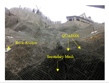
Figure 2:Treatment of location-3 slope by applying TECMAT below TECHO and rock anchors.
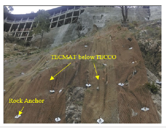
Scaling of surface i.e., removal of loose materials and small rock chunks was done before applying protection measures. Total 106m3 material was excavated by mechanical means i.e., hydraulic excavator and manual means. Slope was treated with QUAROX to hold the fractured rock mass on the cliff of rock and TECCO for treatment of slopes where small rock fragments/debris were present. Below QUAROX, secondary mesh, made of G.I. wire of dia. 2.4 mm was placed. Erosion control mat (TECMAT) below TECCO in debris covered areas was applied to support vegetation. TECMAT is made up of Polypropylene (PP) monofilaments and is typically used in combination with a TECCO mesh cover and an appropriate nailing. TECMAT was applied as a bioengineering measure in a 1360m2 area. Where QUAROX was applied, full column grouted (1:1 sand & cement), 8.0m length and 28mm dia. anchor bolts at a spacing of 2.0m c/c in staggered fashion were installed. Where TECCO was applied, full column grouted (1:1 sand & cement), 6.0m length and 25mm dia. anchor bolts at a spacing of 2.0m c/c in staggered fashion were installed. For grouted rock anchors, dia. of hole was 90mm and 70mm dia. for 28mm and 25mm anchor bolts respectively. In other areas also wherever required, 25mm dia., 6.0 – 8.0m length grouted rock anchor bolts were installed. 100mm thick shotcrete in 2 layers with chain link mesh was applied on the rock surface after cleaning of slope. The chain link fabric was made up of G.I. wire of dia. 2.8mm and it was anchored with a 1.0m length dowel. Concrete cladding wall of M-25 grade is constructed just below the temple. Consolidation grouting (1:2 & 1:3 water & cement) through 38mm dia. holes up to 10m depth were done in the cladding wall at 2.0m interval from the bottom. Consolidation grouting was also done throughout the area with the same specification with 2 to 4kg/cm2 pressure. Anchoring of the cladding wall was done using 25mm dia. steel bars up to 6 m depth (staggered) at 2.5m c/c spacing.
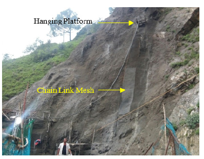
Location no. 7 is located between Ardhkuwari and Mata Bhawan (new track) at chainage 0.925 to 1.000km. The major geological discontinuities mapped are: (i) bedding – N140o (strike)/45o (angle of dip)/N50o (dip direction), (ii) J1 – N240o/65o/N150o and (iii) J2 - N135o/65o/225o. Average slope angle is 70o towards N150o. The rocks are well traversed by three sets of joints i.e., B, J1 and J2, each being nearly perpendicular to each other (Figure 3). The slope direction being N150o, the joint J1 controls the slope being parallel to it. The bedding and joint J2 act as release joints. High energy absorption rockfall barriers, shotcrete, drainage holes and consolidation grouting treatments were applied for this slope (Figure 4). 100mm thick shotcrete in 2 layers with chain link mesh was applied on the rock surface after cleaning of slope from Ch. 0.890 to 0.950km, between El. 1470 to 1570m. Aluminium saltbased white powder accelerator (MasterRoc SA 540) was used to reduce the rebound. The chloride ion content in this white powder was <0.1 percent and bulk density was between 500-700kg/m3. One stage consolidation grouting through 38mm dia. holes up to 10m depth at 3m c/c spacing (staggered) was done from chainage 0.900 to 0.940km., between El. 1520 and 1570m. 40 numbers of drainage holes of 76mm dia. and 10m deep are provided from Ch. 0.890 to 0.950km at 6.0m c/c spacing (staggered) from El. 1470 to 1500m. Tension cracks were filled and sealed by cement slurry. In this location, at 4 places, rockfall protection barriers are constructed. Two numbers (profile number 1 & 3) of 6m high and 40m long each, rockfall barriers of minimum energy absorption in the entire system of 5000K.J. are constructed at El. 1475m and 1540m. Two numbers (Profile 2 & 4) of 5m high and 30m length each, rockfall barriers of minimum energy absorption in the entire system of 3000K.J. are constructed at El. 1490m and 1580m.
Figure 3:View of location-7 slope before treatment
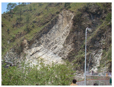
Figure 4:In location-7 two layers of shotcretes were applied along with chain link mesh.
Location no. 14 is located between Ardhkuwari and Mata Bhawan (new track), just before Panchhi staff colony at chainage 3.850 to 4.250km. At site-14 limestone exposed in the area is well jointed with well-developed bedding planes. The rock was weathered close to the surface making to discontinuities to open up and making rock wedges more unstable and loose in nature. In view of closely spaced beddings, the resultant rock wedges were small in nature. They stick to the surface due to secondary cementation. The discontinuities mapped are: (i) bedding - N310o (strike)/35o (angle of dip)/N40o (dip direction), (ii) J1 - N50o/65o/N320o and (iii) J2 - N350o/60o/260o. Average slope angle is 50o towards N290o. The bedding dips askew to the direction of slope. But the rock wedge formed due to joints J1 and J2 has a plunge towards the direction of the slope, but with nearly 15o difference. Hence, it is a potential wedge to cause wedge failure. But since the plunge amount is more than that of the slope, it will be ineffective to cause any actual wedge failure. High energy absorption rockfall barriers and high tensile rolled cable net with anchors were applied for this slope. At two places, QUAROX above secondary mesh was applied to hold the fractured rock mass on the cliff area (Figure 5). QUAROX was anchored with full column grouted (1:1 sand & cement), 6.0 m length and 28mm dia. anchor bolts at a spacing of 3.0m c/c in staggered fashion. Dia. of hole for anchor bolts was 90mm. In an 1875m2 area high-tensile rolled cable net was applied. 5m high and 60m & 50m long rockfall barriers at profile no 1 & 3 respectively, of minimum energy absorption in the entire system of 3000K.J. are constructed at El. 1675m and 1690m (Figure 6). 9m high and 25m long rockfall barrier at profile no 2 of minimum energy absorption in the entire system of 8000K.J. is constructed at El. 1680m. 6m high and 20m long rockfall barrier at profile no 5 of minimum energy absorption of 5000K.J. is constructed at El. 1710m. 7m high and 30m long rockfall barrier at profile no 4 of minimum energy absorption of 5000K.J. is constructed at El 1670m. Gaps between the rockfall barriers and rock surface were properly plugged by proper installation of net and anchors.
Figure 5:Treatment of location-14 slope by applying QUAROX with secondary mesh and rock anchors.
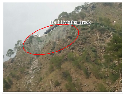
Figure 6:View of 5m high, 60m long rockfall barrier built at El. 1675m.
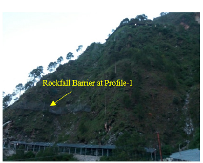
Location no. 16 is located between Ardhkuwari and Mata Bhawan (new track), before battery cars stand at chainage 5.075 to 5.375km. At location-16 area, hard and more massive rocks are exposed in the area on steep to vertical slopes. Overhangs are seen on the slope just above the pathway formed mainly due to excavation of the bottom slopes. Since the rocks are weathered close to the surface, the intersection of joints and closely spaced bedding planes within the rocks had resulted in the formation of many small rock wedges, which lie nearly loose on the surface. The discontinuities mapped are: (i) bedding - N305o (strike)/55o (angle of dip)/N35o (dip direction), (ii) J1 - N330o/45o/N240o and (iii) J2 - N20o/70o/290o. Average slope angle is 75o towards N325o. All the geological discontinuities dip in different directions as compared to the slope. However, many of the rock wedges formed due to intersection of these discontinuities dip in the direction of the slope. Except the intersection by J1 and B the other intersections have their direction of plunge more than 20o as compared to slope direction. Only the direction of the plunge of intersection by J1 and B is very close to the direction of the slope, but the plunge amount is too low (about 15o) to cause a landslide. Treatment applied for this slope are high energy absorption rockfall barriers, high tensile rolled cable net with anchors, anchor bolts and drainage holes.
At two places, QUAROX above secondary mesh was applied in an 1800m2 area to hold the fractured rock mass (Figure 7). QUAROX was anchored with full column grouted (1:1 sand & cement), 8.0m long and 28mm dia. anchor bolts at a spacing of 2.0m c/c in staggered fashion. Size of hole was 90mm dia. for grouted anchor bolts. In other areas wherever required, 25mm dia., 6.0m long grouted rock anchors were installed and the dia. of hole was 50mm. Wherever required consolidation grouting through 38mm dia. holes up to 10m depth were done at one stage. 15 numbers of drainage holes of 76mm dia. up to 10m depth are drilled between Ch. 5.150 and 5.200km. 6m high and 30m long rockfall barrier at profile no 1 of minimum energy absorption of 5000K.J. is constructed at El. 1770m. 5m high and 55m long rockfall barrier at profile no 2 of minimum energy absorption of 3000K.J. is constructed at El. 1785m (Figure 8). 6m high and 40m long rockfall barrier at profile no 3 of minimum energy absorption of 3000K.J. is constructed at El 1820m. 6m high and 30m long rockfall barrier at profile no 4 of minimum energy absorption of 3000K.J. is constructed at El 1830m. Gaps between the rockfall barriers and rock surface were properly plugged by proper installation of net and anchors.
Figure 7:Treatment of location-16 slope by applying QUAROX with secondary mesh and rock anchors.
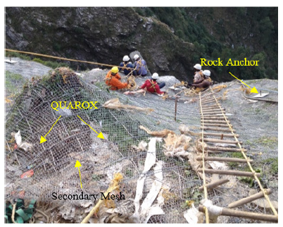
Figure 8:View of 5m high, 55m long rockfall barrier built at El. 1785m.
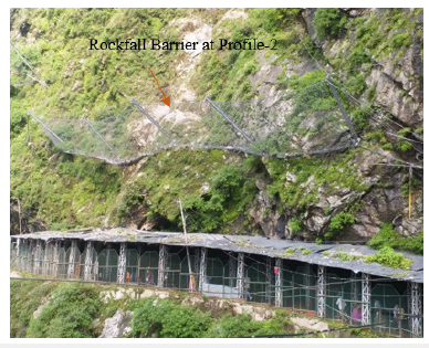
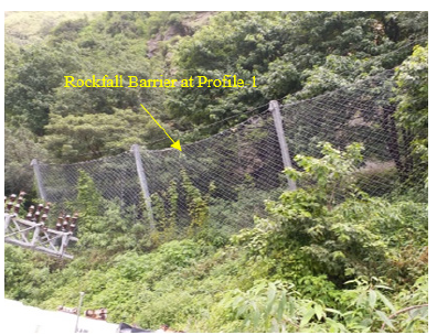
Location no. 17 is located between Ardhkuwari and Mata Bhawan (new track), 100m from Manokamna Bhawan & 50m from Junction of Old and New Trek at chainage 5.450 to 5.525km. At location-17 rocks are not exposed in the area near the footpath track. A thick debris cover is seen on the entire slope in the area. The slope has a number of dislocated rock blocks seen scattered on the slope. The toe retaining wall provides effective support for the debris lying above. The backside slope is nearly vertical and extends to a very large high (Figure 9). This area is protected with two high energy absorption rockfall barriers. At this location, a 6m high and 25m long rockfall barrier at profile no 1 of minimum energy absorption of 3000K.J. is constructed at El. 1790m (Figure 10). 7m high and 25m long rockfall barrier at profile no 2 of minimum energy absorption of 5000K.J. is constructed at El. 1765m. Gaps between the rockfall barriers and debris are properly plugged with gunny bags filled with sand. The site conditions prohibit implementation of other measures except what has been provided. Additional chain link fabric along the systems has been provided by SMVDSB as an additional safety feature.
Figure 9:View of back slope, which is vertical and very high.
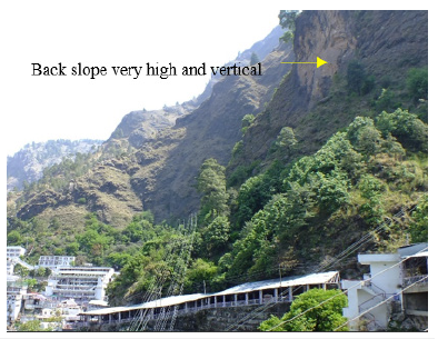
Figure 10:View of 6m high, 25m long rockfall barrier built at El. 1790m.
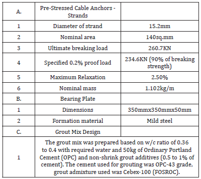
At about 13:30 hours on 12th March 2016, track between elevator point and gate no. 5 at Bhawan got damaged due to heavy and continuous rain which led to landsliding. Aged Durga Bhawan building had to be dismantled for construction of a new Bhawan and because of this existing toe support was disturbed. Slope failed near the dismantled Durga Bhawan, taking away about 22m part of the footpath and it was very hazardous for the movement of pilgrims (Figure 11). Immediately after this incident, a site was visited and keeping in view the importance of the Bhawan area and the convenience of pilgrims, as an immediate measure, 6m & 10 deep drilling for consolidation grouting was started to consolidate the rock mass which in turn checks further damage to the track and nearby area. 20 boreholes were drilled, 10nos. were 6m deep and balanced 10m deep (Figure 12). A proper assessment was done and a stretch of 58m was identified as vulnerable. For the long-term stability of the Bhawan area and the structures located above the slope, anchored cladding wall along with RCC retaining wall with pre-stressed cable anchors were proposed, designed and constructed (Figure 13). At the base, a 100mm thick levelling course of M-10 grade was made and above this 500mm thick M-20 raft was constructed. Width of footing was between 3500 and 4000mm. Raft was anchored with fully grouted 25mm dia. rod at 1500m c/c spacing (6m in rock and 1m in concrete). Above the raft, a 6.0m high of M-20 concrete cladding wall was constructed. Cladding wall was anchored with fully grouted 25mm dia. rod at 2500m c/c spacing (6m in rock and 3m in concrete). 100mm dia. MS drain pipes inclined at 100 at 2400mm c/c spacing at every lift of concrete (staggered) in the cladding wall were installed. Lift height was 1500mm. 6.60m high RCC wall of M-25 grade was constructed above the cladding wall. RCC wall footing was anchored with two rows of anchors of fully grouted 25mm dia. rod at 2500m c/c spacing (6m in cladding/rock and 1m in concrete). 100mm dia. MS drain pipes inclined at 100 at 2400mm c/c spacing at four elevations (staggered) in the RCC wall area were installed. 200mm dia. MS pipe normal to the foliation plane for cable anchors at 1500mm c/c were installed. In the RCC wall area, back filling was done with plum concrete. The RCC wall was anchored with prestressed cable anchors of 100 T capacity and depth varying from 26.5m to 30.5m and a total of 1088.5R/M anchoring was done through 37 drilled holes. 26 anchors are of 30.5m length while 11 numbers of 26.5m length. For prestressed cable anchors, high tensile strands (seven ply strand) conforming to IS-14268 class 2, manufactured by Usha Martin Ltd were used [6]. This whole process leads to building a monolithic structure capable of resisting active as well as passive loads on slope. The major interventions involved under the scope are given in Table 1. The technical specifications for some of the major components are given in Table 2.
Figure 11:View of 6m high, 25m long rockfall barrier built at El. 1790m.
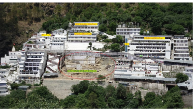
Figure 12:Location of consolidation grouting.
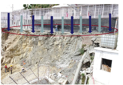
Figure 13:Restoration track at Durga Bhawan.
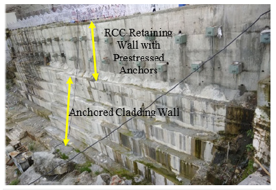
Table 1:Description of major work component.
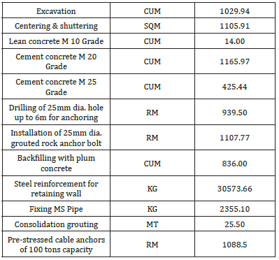
Table 2:Technical specifications.
Properties of the Materials
Material properties used for the protection measures were certified by various accredited laboratories in India and European Organization for Technical Approvals (EOTA) [7]. Eight samples for Ordinary Portland Cement (OPC) of grade-43 and three samples of OPC grade-53 were tested and they comply with IS: 8112-2013 and IS: 12269-1987 respectively [8,9]. Three samples are tested for compressive strength of M-25 concrete cubes in respect of 7 days strength. The area of each sample was 22500mm2; volume was 3375000mm3; load at failure for three samples applied were 450, 530 and 450kN. The strength of three samples tested was 20.00, 23.56 and 20.00N/mm2 and average strength was 21.19N/ mm2. Minimum required strength in 7 days is 17.5N/mm2. 25mm and 28mm dia. anchor bolts were used for the anchoring of rocks, cable net and wire mesh with ground. For 25mm dia. anchor bolt, four samples were tested, and nominal mass was 3.805kg/m, tensile strength was ranging from 622.00 to 683.00N/mm2, yield strength was 525.00 to 581.00N/mm2 and elongation was 20.72 to 21.6%. One sample of 28mm dia. anchor bolt was tested, yield strength tested was 672.53N/mm2. No crack was observed during bend and rebend tests of 25mm and 28mm dia. anchor bolts and the material conforms to the standard rolling and weight tolerance. The test result conforms to the BIS specification IS:1786-2008 for grade Fe500D [10]. In high-tensile rolled cable net area, the size of the base plate used was 200(l)x200(w)x10(t). The hole diameter of this plate was 30mm and zinc coating was 803.15g/m2. In hightensile steel wire mesh area, the size of the base plate used was 300(l)x200(w)x10(t). The hole diameter of this plate was 41mm and zinc coating was 901.03g/m2. Pull-out strength tests were performed to verify the short-term strength of an installed rock bolt with respect to design limit [11,12].
The applied load was measured by a pull testing equipment installed on the rock bolt. The test equipment used consists of a manually operated hydraulic pump connected to a hydraulic jack of 50 tons capacity, having a high strength test rod, directly coupled to the rock bolt under test. This test is usually employed to assess the performance of the rock bolt anchor resulting out the quality used for manufacture of rock bolt and installation method used. Total 39 anchor bolts (29nos. 8.0m long and 10nos. 6.0m long) were tested from locations 3, 14 and 16. The dia. of anchors were 25mm and 28mm and design load was 30 and 35 tones. The rock bolts were tested maximum up to a load of 10 percent more than the design load and no failure was observed between grout-rock bond as well as anchor-grout bond. The displacements which were observed during the test were primarily due to the compression/settlement of ground near the anchor plate. All the rock bolts tested were found apparently safe under short-term stability for the maximum pull-out load applied with respect to the designed load.
For high-tensile rolled cable net, size of mesh was 390x400mm, wire diameter was 3.0mm, tensile strength of steel wire was ≥1770N/mm2, tensile resistance of a wire was ≥12.5kN, tensile strength (load capacity) of net longitudinal was ≥100kN/m, minimum breaking load was 65kN, corrosion protection (galfan coating) was 95% Zn+5% Al, coating min. was 150gm/m2, diameter of spiral rope was 6.5mm (construction - 1x3) and top/bottom/ lateral boundary rope minimum size was 14mm dia. For hightensile rolled cable net wire, three samples were tested, tensile strength tested was 1800.74N/mm2, zinc/aluminium coating was 154g/m2 and no sign of corrosion was reported. For high-tensile strength steel wire mesh, size of mesh was 83x143mm, wire diameter was 3.0mm, tensile strength of steel wire was ≥1770N/ mm2, tensile resistance of a wire was 12.5kN, tensile strength (load capacity) of mesh was ≥150kN/m, bearing resistance against puncturing was ≥180kN, bearing resistance against shearing-off was ≥90kN, bearing resistance against slope-parallel tensile stress was ≥30kN, elongation longitudinal with a tensile load=150kN/m was 6.5%, corrosion protection (galfan coating) - 95% Zn+5% Al, coating min. was 150gm/m2, diameter of spiral rope was 6.5mm (construction - 1x3) and top/bottom/lateral boundary rope min. was 12mm dia. For high-tensile strength steel wire mesh, three samples were tested, tensile strength tested was 1783.43N/mm2, zinc/aluminium coating was 154g/m2 and no sign of corrosion was reported.
For secondary mesh, size of mesh was 25x25mm, wire diameter was 2.4mm, yield strength of steel wire was ≥480N/mm2 and Zn coating was 240gm/m2. For the secondary mesh, three samples were tested, yield strength tested was 500.32N/mm2, zinc coating was 248g/m2 and no sign of corrosion was reported. For chain link fabric, size of mesh was 50x50mm, wire diameter was 2.8mm, tensile strength of steel wire was 570N/mm2, and yield strength of steel wire was 480N/mm2. For chain link fabric, one sample was tested, tensile strength of wire tested was 633.73N/mm2, yield strength reported was 519.98N/mm2 and elongation was 10.71%. Erosion control mat (TECMAT) applied was a three-dimensional structural mat of Polypropylene (PP) monofilaments used in combination with TECCO mesh cover and an appropriate nailing. The thickness of the irregular loopy structure erosion control mat was 18mm, specific mass was 600g/m2, void ratio was >95% and tensile strength was ≥1.8kN/m. Rockfall barrier systems installed are of energy absorbent capacity 3000KJ, 5000KJ, 8000KJ which are certified by European Organization for Technical Approvals (EOTA). They were applied after proper design in identified risk areas, so that risks of injury and loss of property can be reduced substantially.
Conclusion
The executing agencies comprise Consortium of M/s PFE Thane and M/s Geobrugg AG Switzerland completed the protection/ treatment work of five locations i.e. 3, 7, 14, 16 & 17 in 34 months while the stipulated time for the completion of work was 21 months. Stipulated cost was 11.98 crores while actual cost was 18.05 crores which is an increase of approximately 50.74 percent. The delay was because of applying the additional protective measures, terrain and local climatic conditions. Protection/ treatment work of dismantled Durga Bhawan slope area was completed in 9 months while the stipulated time for the completion of work was 6 months. Stipulated cost was 5.44 crores while actual cost was 5.78 crores which is an increase of approximately only 6.29 percent. The work was done as per the approved drawings/ designs. Material properties were certified by various accredited laboratories and European Organization for Technical Approvals (EOTA). It was recommended that maintenance of rockfall barriers should be done which should include replacement of damaged part and cleaning the barriers after every rockfall event. Inspection and maintenance of rockfall barriers are an absolute requirement to ensure the desired protection level. It was also underlined that the periodic cleaning of weep holes shall also be done. In the first phase, at five locations of problematic landslides/shooting stone areas, support/protective measures are installed, which achieved the objectives of whole scheme. It was recommended that same can be replicated at the new identified locations after detailed design. After recommendation, in phase-II, the protection work is being carried out at location nos. 4, 12, 15, 25, (2 no. nala at new track), Tarakot Police Chowki and balance works at location no. 7.
Acknowledgement
This paper is a part of sponsored project by M/s SMVDSB, so we sincerely thank the management of SMVDSB for the same. We also thank management of SMVDSB for providing all the geological and geotechnical data for review and analysis. First author is thankful to Director NIRM for the permission to send the manuscript for publication.
References
- SMVDSB (2014) Report on the protection/treatment work on slopes of track between Ardhkuwari to Mata Vaishno Devi Ji Shrine (Bhawan), Phase-I at Katra, Jammu and Kashmir. Report by Shri Mata Vaishno Devi Shrine Board (SMVDSB), p. 105.
- Wadia DN (1937) Permo-carboniferous limestone inliers in the sub-Himalayan Tertiary zone of Jammu and Kashmir Himalayas. Record Geological Survey of India 71(2): 162-173.
- Raha PK (1978) Tectonic setting of the Riasi inlier of the Jammu limestone, District Udhampur, Jammu and Kashmir. Himalayan Geology 8(1): 349-368.
- Anbalagan R (2013) A report on geological mapping and slope stability problem along pathway of Shri Mata Vaishno Deviji Shrine. Report submitted to THDC India Limited, p. 79.
- Singha G, Dutta L (2017) Rock slope stabilization along the track route to Mata Vaishno Devi Shrine - A Case Study. ISRM India 6(2): 22-26.
- IS 14268 (1995) Uncoated stress relieved low relaxation seven-ply strand for prestressed concrete specification. Bureau of Indian Standards, p. 5.
- SMVDSB (2016) Report on the product manual and specification for the material and material test certificates for the protection/treatment work on slopes of track between Ardhkuwari to Mata Vaishno Devi Ji Shrine (Bhawan), Phase-I at Katra, Jammu and Kashmir. Report by Shri Mata Vaishno Devi Shrine Board (SMVDSB), p. 110.
- IS 8112 (2013) Ordinary Portland cement 43 grade specification. Bureau of Indian Standards, p. 10.
- IS 12269 (1987) Specification for 53 grade Ordinary Portland cement. Bureau of Indian Standards, p. 5.
- IS 1786 (2008) High strength deformed steel bars and wires for concrete reinforcement - specification (fourth revision). Bureau of Indian Standards, p. 12.
- ATES (2016) A report on pull-out test of rock bolts/anchors for protection and slope stabilization work on alternating track from Ardhkuwari to Bhawan Phase-I, Katra, Jammu and Kashmir. Report by Advanced Technology and Engineering Services (ATES), p. 8.
- IS 11309 (1985) Method for conducting pull-out test on anchor bars and rock bolts. Bureau of Indian Standards, p. 6.
© 2023 Naithani AK. This is an open access article distributed under the terms of the Creative Commons Attribution License , which permits unrestricted use, distribution, and build upon your work non-commercially.
 a Creative Commons Attribution 4.0 International License. Based on a work at www.crimsonpublishers.com.
Best viewed in


.jpg)


 Editorial Board Registrations
 Submit your Article
 Refer a Friend
 Advertise With Us
.jpg)


.jpg)


.bmp)
.jpg)
.png)
.jpg)


.jpg)


.png)

.png)


.png)


