- Submissions

Full Text
Aspects in Mining & Mineral Science
Groove Making in a Tubing Lining Elements
Paweł Kamiński*
Faculty of Civil Engineering and Resource Management, AGH University of Science and Technology, Poland
*Corresponding author: Paweł Kamiński, Faculty of Civil Engineering and Resource Management, AGH University of Science and Technology, Mickiewicza, Poland
Submission: June 12, 2021;Published: June 17, 2021

ISSN 2578-0255Volume6 Issue5
Opinion
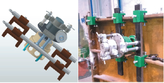
Tubing lining is used as the final lining of shafts sunk in extreme hydrogeological conditions, and it is composed of a cylinder made of separate rings. Individual rings are composed of separate, equal segments called tubings. Tubings can be made of reinforced concrete, cast iron and steel. Steel tubings, having dimensions depending on the shaft diameter, have the form of a metal pipe [1-4]. Despite of high durability of the tubing lining, damages of the lining in form of leakages, scratches and fractures can occur. The most common causes of these damages are material faults and hydro-geological conditions [4-9]. The damages of the tubing lining are direct danger for the shaft operation because they are usually a cause for a water inflow to the shaft. The safety of mining excavations is considered dangerous, because the devastation of the lining usually comprises a bigger zone, and the possibility of more intensive water leakage related with rock mass movements is quite realistic [5,7,10]. Different methods of tubing lining repair and protection were invented and used over the years. All of them comprise of some kind of the reinforcement of the damage to seal the tubing lining. For the purpose of efficient and safe sealing of the tubing lining, PBSz S.A. uses a sealing method by making a closed circumference groove around the sealed area in the internal shaft wall, whereas the groove depth must be smaller than the tubing depth. Then the sealing element is placed in the groove and pressed with spatial insert closed in the top side and having a hole for the injection of the sealing medium. In the next stage, the insert is mounted to the lining and then the sealing medium is injected in. When the process is finished, the insert hole is closed. A specially designed milling machine is used for making grooves in shaft tubing lining. The milling machine is composed of the power transmission system and a construction for tubing and advance mechanism mounting. A battery drill-driver is used as the milling machine driving system, and the whole device is mounted to the tubing with the use of specially designed guides with handles. A model and a photograph of the tubing milling machine is shown in Figure 1.
Figure 1: A model and a view of the tubing milling machine.

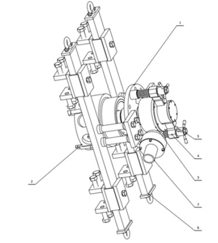
Figure 2: Milling machine construction; 1-main plate with mandrel and threaded sleeve; 2-milling head; 3-worm gear, 4-hub with guides and mounting device, 5-mounting to main plate device, 6-guides with mounting-depending on the chosen option: •round for mounting milling machine with handles, •rectangular for mounting the milling machine with handles; 7-planetary gear with driving system housing.

References
- Kostrz J (2014) Sinking of Shafts. Library of the School of Underground Exploitation, Kraków, Poland.
- Kostrz J (1964) Shafting with special methods, Wydawnictwo Śląsk, Katowice, Poland.
- Czaja P, Kamiński P (2016) Selected issues of technique and technology of shaft sinking. School of Underground Exploitation, Kraków, Poland.
- Obyrn K, Kamiński P, Motyka J (2021) Influence of hydrogeological investigation’s accuracy on technology of shaft sinking and design of shaft lining-case study from Southern Poland. Energies 14(8): 2050.
- Judeel G, Keyter GJ, Harte ND (2011) Shaft sinking and lining design for a deep potash shaft in squeezing ground. In: 12th ISRM Congress, Beijing, China.
- Niedbalski Z, Małkowski P (2020) Difficulties in maintaining shaft lining-testing methods and repair methods–A case study. In E3SWeb of Conferences, China.
- Mishedchenko A, Kuzina A (2016) Investigation of tubing lining loss of tightness causes. Applied Mechanics and Materials 843: 33-35.
- Wang L, Cheng YP, Ge CG, Chen JX, Li W, et al. (2013) Safety technologies for the excavation of coal and gas outburst-prone coal seams in deep shafts. International Journal of Rock Mechanics and Mining Science 57: 24-33.
- Czaja P, Kamiński P, Dyczko A (2020) Polish experiences in handling water hazards during mine shaft sinking. InTech Open, Poland.
- Fabich S, Kokot B, Kulicki J, Szlązak M (2007) Tubing lining of shafts in LGOM: Causes of damage to the lining, applied damage prevention and repair methods. Mining and Geoengineering 3: 113-125.
© 2021 Paweł Kamiński. This is an open access article distributed under the terms of the Creative Commons Attribution License , which permits unrestricted use, distribution, and build upon your work non-commercially.
 a Creative Commons Attribution 4.0 International License. Based on a work at www.crimsonpublishers.com.
Best viewed in


.jpg)


 Editorial Board Registrations
 Submit your Article
 Refer a Friend
 Advertise With Us
.jpg)


.jpg)


.bmp)
.jpg)
.png)
.jpg)


.jpg)


.png)

.png)


.png)


