
- About Us
- Information
-

The Author ensures that the research has been conducted responsibly and ethically with adherence to all relevant regulations. read more..
- For Authors
- For Reviewer
- Manuscript Guidelines
- Membership
- Publication Ethics
-
- Journals
- Reprints
- e-Books
- Videos
- Policies
- Contact Us
 COVID-19
- Submissions


Full Text
Aspects in Mining & Mineral Science
Design and Construction of Rock Crushing Machine from Locally Sourced Materials for Indigenous Use
Ocheri C*1, Aigbodion VS2, Agboola JB2, Mbah CN3 and Mbah AC3
1 Department of Metallurgical and Materials Engineering, University of Nigeria, Nigeria
2 Department of Metallurgical and Materials Engineering, Federal University of Technology, Nigeria
2 Department of Metallurgical and Materials Engineering, Enugu State University of Science and Technology, Nigeria
*Corresponding author: Ocheri C, Department of Metallurgical and Materials Engineering, University of Nigeria, Nsukka, Enugu State, Nigeria, Tel: 08068433419; Email:cyril.ocheric@unn.edu.ng
Submission: May 26, 2018;;Published: August 07, 2018

ISSN 2578-0255Volume2 Issue2
Abstract
The design and construction of a prototype rock crushing machine was performed this is with a view to ensuring that the designed crusher is capable of crushing rocks, lime stone and solid minerals for indigenous use. The research work was tailored mainly on the design and production of locally fabricated rock crushing machine for indigenous use. To accomplish the entire work within the scope of time therefore necessary parameters were considered, the following activities were also performed according to the procedures discussed in the research work. Available crushing machines in mines were studied to ascertain their associated prospects, challenges and problems. Extensive research was carried out using existing data and information-based literature survey that was used. Detailed design analysis was performed with a view to catering for all the identified challenges. A prototype was constructed to evaluate the design analysis carried out. Rock crushing machines are highly essential in the mineral processing and extractives industries. The few machines in use today in most industries are imported, thus raising the cost of production and depleting foreign exchange earnings. Locally designed rock crushing machines have lot of benefits which translate to job creation, revenue generation and wealth creation. This provides amble opportunities for Government, stakeholders, corporate bodies and individual alike to own such machine since they are affordable since they are manufactured locally which signifies that such machines could be attended to easily by the manufacturer in case of any failure or malfunctioning. It reduces importation, thus fighting the depleting foreign exchange earnings.
Keywords: Design; Construction; Rock machine; Indigenous and use
Introduction
Crushing is one of the preliminary stages in mineral processing from the ore. The process is required to reduce rocks and lumps to smaller pieces. Rollers or jaw crushers are employed in this situation. The jaw crusher is a rocks or lumps reduction machine that employs two hardened manganese steel jaws, with one in relative motion against the other which is stationary while the roller crusher utilizes two cylinders mounted on horizontal shafts. The common challenge faced by the mineral processing industries with respect to the jaw crusher is related to frequent wear of the jaw and shaft components. This challenge contributes to depletion in national foreign exchange earning when this component had to be imported whenever there is a failure. There is therefore a need to adapt the jaw crusher technology to make it suitable and readily maintainable within the Nigerian mining industry. This must be achieved without any compromise as regard the machine performance and suitability of its operation. The shaft of a typical jaw crusher machine is made of hardened steel (high carbon steel). It puts the moveable jaw stock in motion (through the motor, pulley and belt arrangement) that produces the needed force to crush materials.
Components of jaw crusher
In this machine, various parts (components) are inter-linked together by bolting, welding and trapping (confining) to build a functioning Jaw crusher. Most of these components are discussed below.
Moveable jaw stock
The moveable jaw stock is the main moving part in a jaw crusher. It forms the moving side of the jaw, while the stationary or fixed jaw forms the other. It achieves its movement through the eccentric movement of the crusher main shaft. It is the back and front (to and fro) movement of the moveable jaw stock that gives the tremendous crushing force to each stroke. The moveable jaw stock comprises of the grease drum and the part where the high manganese steel die (jaw) is fixed (Figure 1). Manganese (Mn) is a hard, silvery white metal with a melting point of 1,244 ᵒC (2,271 ᵒF). Ordinarily too brittle to be of structural value itself, it is an essential agent in steelmaking, in which it removes impurities such as sulfur and oxygen and adds important physical properties to the metal. For these purposes it is most often employed as a ferromanganese or silico manganese alloy.
figure 1:Moveable stock

Eccentric shaft
This is made of hardened steel (high carbon steel). It put the moveable jaw stock in motion as a result of the eccentric lobe on the shaft as shown in Figure 2 It is this motion that produces the needed force to crush materials.
figure 2:Moveable stock

Moveable jaw (manganese die)
figure 3:Moveable jaw.

This is carried in the inward face of the moveable jaw stock; it is made of manganese, an extremely hard metal. Manganese, as an alloying agent, improves strength, hardness; harden ability, and abrasion resistance. Its alloy with steel results to a wear-resistant steel noted for its capacity to be work-hardened. Moveable jaw is usually made symmetrical top to bottom with scalloped face as in Figure 3 and can be flipped over. During use, it wears in the bottom (closed side) of the jaw and flipping it over provides another equal period of use before replacement.
Fixed jaw (manganese die)
This is statically mounted to the fixed stock and is positioned opposite to the moveable jaw. It is also made of high manganese steel.
Crusher pulley and flywheel
These are not different from normal pulley and flywheel we see around. The only thing is that both are carrying additional weight to help in maintaining rotational inertia as the jaw crushes material. Rotational energy is fed into the jaw crusher eccentric shaft by means of grooved pulley which usually has multiple V belt grooves (Figure 4). For balancing, both the pulley and the flywheel are designed in such a way that they have approximately equal weight; this will help to minimize vibration.
figure 4:Pulley and flywheel.

Cheek plates
The positioning of these plates on the jaw crusher justifies the name “Cheek Plates”. They are made or coated with high strength manganese steel for durability purpose. As it can be seen in the assembly drawing, the design is done in such a way as to act as additional lock to key down the fixed jaw to its stock. Figure 5 shows the left and right cheeks of this crusher
figure 5:Left and right cheeks.

Toggle plate
This is a piece of metal that acts as support to the bottom of the moveable stock. It serves the purpose of allowing the bottom of the moveable stock to move up and down with the motion of the eccentric shaft. Toggle plate also serves as safety mechanism for the entire jaw by getting crushed and prevent possible damage in a situation whereby a piece of non-crushable material such as steel loader tooth (tramp iron) enter the jaw and cannot find its way out due to its size compare to the closed side setting Figure 6.
figure 6:Toggle plate

Tension rod
It is this rod with its spring that prevents the flopping around of the moveable stock. The toggle plate rest on the toggle seat and has no connection with the moveable stock. Absence of tension rod renders the toggle plate useless Figure 7.
figure 7:Tension rod and its accessories.

Side plates (main frame)
These are the two side plates that form the main frame of the jaw crusher. The dimension determines the size of the jaw crusher. The major components of crusher are assembled within the side plate (Figure 8)
figure 8:Side plate (Main Frame).

Eccentric shaft bearings
The Eccentric shaft carries four bearings. Two of these bearings are situated at the crusher frame, supporting the shaft while the other two are situated at each end of the moveable jaw stock.
Jaw crusher adjustment
Depending on the disposition of the material being crushed by the jaw, different size of material may be required. This is achieved by adjusting the opening at the bottom of the jaw (i.e. the closed side setting). This is done by turning the opening adjuster Nut clockwise anticlockwise for closing opening Figure 9.
figure 9:Adjustment mechanism.

Design analysis for shaft
A shaft is a rotating machine element which is used to transmit power from one place to another on a machine. This involved the transmission of torque and bending moment. Hence shaft design consists primarily of the determination of the correct shaft diameter to satisfactory strength and rigidity, needed for the required torque under various operating and loading condition. In order to meet up with torsion bending and axial loads during operation of this machine, solid shaft is chosen for the design Figure 10.
figure 10:Cross Section of V-belt

Torsion: for a solid circular shaft of diameter, d, the maximum shear stress is
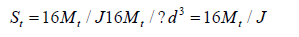
It is assumed that failure is based on the maximum shear stress theory or Guest’s theory. It is used for ductile material such as mild steel quantitatively. It is given by
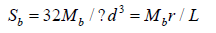
Bending: the bending stress Sb (tension or compression) is given as
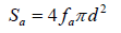
Axial loading: the tensile or compressive stress is given as
The asme: code equation for a hollow shaft combines torsion, bending and axial loads by applying the maximum shear equation modified by introducing shock, fatigue and column factor is illustrated above for a solid shaft having little or no axial loading, the code equation reduces to
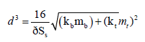
The formula for the shaft diameter design is given by;
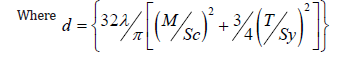
d=shaft diameter m, λ=design factor of safety
Se=part fatigue endurance strength (N/M2),
M = moment (Nm)
T=torque (Nm), Sy=yield strength (N/m2)
Se=0.5KSu
K=Ka Kb Kc Ke Kd Kf
Where Su=ultimate strength of material N/m2
K=fatigue modification factor,
Ka=surface condition fatigue modification factor.
Kb = size fatigue modification factor,
Kc=reliability goal fatigue
Ke=stress concentration
Kf =miscellaneous – effect modification factor
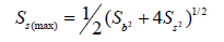
Using (ASME) equation
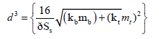
Where Ss=Allowable shear stress
Mb=bending moment
Mt =torsional moment
Kb = combined shock and fatigue factor applied bending moment
Kt= combined shock and fatigue factor applied to torsional moment
ASME codes for commercial steel shafting are
Ss (allowable)=55MN/m² for shaft without key way
Ss (allowable)=40MN/m² for
The design of shaft for torsional rigidity is a based on the permissible angle of twist, which depend on the particular application and varies about 0.3ᵒ for line shafting

Where θ =Angle of twist (in Degree)
L=length of shaft, m
G=torsional modulus of rigidity N/m²
The torsional moment acting on the shaft is given as
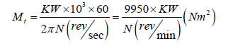
But for a belt drive machine such as the design, the torsional moment is determined as
Mt =(T1 – T2)R, Nm
Where R=Radius of pulley, m
T1=Tension on the tight side, N
T2=Tension on the slack side, N
Vertical loading effect on the shaft
Through calculation and application of mass properties using AutoCAD, the following are obtained:
Vertical weight of pulley on the shaf=180.43kg
Vertical weight of flywheel on the shaft=180.43kg
Weight of the Eccentric shaft=83.2 kg
Weight of the moveable jaw stock =222.6kg
Design analysis for belt drive
Apart from Chain and Gear means of power transmission from one shaft to another, belt is another common means to transmit power by means of pulley. Usually the two pulleys involved, rotate at the same speed or different speed depending on their diameter ratio.
For suitable belt selection, the following factors need to be taken into consideration:
a. Diameter of the pulleys
b. Centre to centre distance
c. Power to be transmitted
d. The required belt speeds
e. Belt cross sectional area.
The power transmitted by a belt drive is a function of belt tensions and belt speed. Belt drive operation depends on the friction between the belt and the pulley.
The belt must be given a certain amount of pre-tension (To), to develop adequate tension.
T = S A
Where Ao=cross sectional area of belt (M2)
So=stress in cross section of the belt (N/M2)
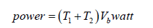
Where T1=Belt tension of tight side (N)
T2=Belt tension on the slack side (N)
Vb=Belt velocity (m/s)
If the thickness of the belt is known and the width is known, the
stress S2 for flat belt is determined by
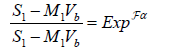
Where S1=Maximum allowable stress, N/m2
S2=Stress in slack side of belt, N/m2
M1=Mass of 1m of belt, kg
Vb=Belt velocity m/s
f =coefficient of friction between belt and pulley
α=angle of wrap of belt on pulley (radian)
Area of belt for this case of the unknown width is determined as
Where A1= required cross section Area, m2
The below Figure 11 shows the cross section of a V-belt. The required belt width (bB) is therefore given as bB= area / thickness =A1/tB
figure 11:Arrangement of belt and pulley.

The maximum tension on tight side of belt depends on the allowable stress of the material.
The, maximum tension on the slack side, T2 is determined by
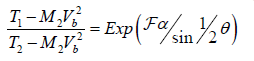
But M2=ρbt
Where M2 =Mass of 1m of belt
ρ=Belt density, kg/m3
b=Width of belt
t=Thickness of belt
Vb=Belt velocity
ƒ=coefficient of friction between belt and pulley
α=Angle of wrap (rad)
θ=Groove angle for the V-belt
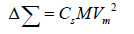
The quantity M2 Vb2 is due to centrifugal force, which tends to cause the belt to leave the pulley and reduces the power that may be transmitted.
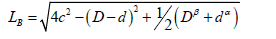
Length of belt is determined by the formula.
Where
r = Radius of motor pulley
R = Radius of shaft pulley
C = Centre distance between two pulleys.
The diagram below Figure 11 shows the arrangement of belt and pulley in action
LB = {π (r + R) + 2C + (R − r) ^ 2}
At the tight side, expected tension = T1
At the loose side expected tension = T2
Belt length and actual centre distance
To determine the belt length and actual centre distance:
Diameter of motor pulley (d) =175
Diameter of shaft pulley (D) =795
The minimum centre distance is given by:
While the maximum centre distance is given by:
Cmax. = 2(D + d ) = 2(175 + 795) =1940mm
Design for belt length
For the standard belt length that is to be used, the expression below gives the minimum
length required.
Where
C = Centre distance
D = diameter of the larger pulley
d = diameter of the smaller pulley
β = angle of contact in larger pulley (radians)
α = angle of contact in smaller pulley.
Grooves in v- belt pulley
The traction force (i.e. force transmitting power) is greater in V-belt than in a flat belt due to the wedging action of a V-belt in the groove of the pulley. In order to ensure wedging action as shown above the belt should make contact with the sides of the groove but not the bottom. The standard angle between the sides of V-belts is 40o, while the groove angle in the pulley ranges from 32o to 38o (less than the belt angle) (Figure 12). Standard sizes of belts for power transmission have been adopted and designated by sizes A, B, C, D and E as indicated in the below Table 1.
figure 12:V-belt in a pulley groove.

Table 1:Criteria for shaft section factor.

Design and analysis for bearing
A bearing is a machine element which support another moving machine element (known as journal) e.g. shafts, axles and other rotating parts of a machine. It permits free motion between moving and fixed parts. Usually, mineral oil, refined from petroleum is used as lubricant to separate the journal and the bearing. But this does not rule out the use of vegetable oils, silicon, and greases etc as lubricants. In this project, semi liquid (grease) is chosen as fixed element.
Lubricants
Lubricants are used in bearing to reduce friction between the rubbing surfaces and to carry away the heat generated by friction. It can be classified into three groups.
a. Liquid (mineral and synthetic oil)
b. Semi liquid (grease)
c. Solid (e.g. graphite)
In this project, semi liquid type of grease is chosen as lubricant. Properties of lubricants such as viscosity, oiliness, density, index, flash point fire point and pour point / freezing point were considered.
Design analysis for pulley
Pulleys generally are used to transmit Power from one shaft to another by means of ropes, V belts and flat belts. In pulley design, the following were noted for higher efficiency. (i) Careful selection of pulleys in order to have a desired velocity ratio (since the velocity ratio is the inverse ratio of the diameter of driving and driven pulley).
ii. Perfect alignment of the pulley so that the belt can travel in line normal to the pulley faces.
iii. Careful selection of material to avoid excessive wear and fragment cut of the belt in use.
Pulley speed (Vp) is given as
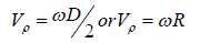
Where
D = diameter of pulley
w= Angular velocity of pulley (rad/sec.)
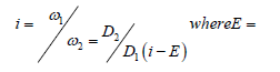
The pulley speed is equal to the belt speed assuming no belt slippage. The velocity (peripheral) ratio is constant i.e. where K = constant when belt assume no slipping

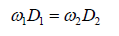
Where i=speed ratio of the belt drive assuring there is belt slippage during drive which lead to a reduction in the expected speed of the drive shaft, the speed ratio with allowance for slippage in given by
to the machines is supplied practically at a constant rate throughout the operation. In a standard flywheel, the maximum fluctuation of speed is the difference between the maximum and minimum speed during a cycle. The mean speed (N) is expressed as:
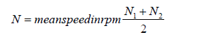
Where N1=maximum speed in rpm during the circle.
N2=minimum speed is rpm during the circle.
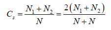
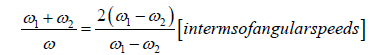
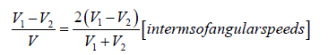
Coefficient of fluctuation of speed
Fluctuation of energy
Where
M = massofflywheel
Production techniques
Considering fatigue, impact, shear and tensile strength of steel, couple with its availability, have made the choice of steel suitable for the Jaw Crusher components. Production of the Jaw Crusher was purely fabrication. Serious welding job and a lot of machining works were carried out on the components. Forging of material and flame cutting of blanks needed, were done in both fabrication and forge shop. Calculation were carried out as per the required length, shape, allowance and quantity needed to avoid waste of material. Hence the following steps were taken towards the production of the Jaw Crusher.
a. Forging of blanks
b. Flame cutting of plates
c. Materials handling
d. Machining of components
e. Quality control
f. Assembly and finishing.
Material selection
The selection of material for a application is governed by the working conditions to which it will be subjected, ease of manufacturing and the cost considerations.
Broadly, engineering materials can be classified as:
a. Metallic materials
b. Non-metallic materials
Metallic materials could further be classified as ferrous metals and non-ferrous metals. While non-metallic materials include plastics, asbestos, rubber, wood, concrete, ceramics etc.
As said earlier, a proper selection must be made to suit the requirement needed. Effective design in engineering calls for our ability to put them to the best use by selecting the right material for a given job.
Parameters considered for material selection
The following parameters were considered for the material selection for the fabrication of the components of this machine.
Physical properties: Physical properties such as density is important in deriving the weight and force the pulley, flywheel and the moveable jaw stock are expected to exert on the shaft member which enable me in estimating the shaft diameter. Density is the ratio of mass of the substance to the volume measure in Kg/m3. The materials are expected to withstand expansion when subjected to temperature above atmospheric temperature. The implication of this is that the material possesses thermal stability. Thermal expansion is the expansion exhibited in meter per unit temperature difference.
Chemical properties: The painting of the main frame board and other mild steel components provide the equipment the ability to withstand dilute chemical environment and solvents, corrosion and weathering effects.
Manufacturing characteristics: These include castability, formability and machinability. All these were considered for components that required such properties.
Cost and availability: For the selection of component materials, special consideration was given to reduce cost of production. It was discovered that some components like flywheel, motor and shaft pulley are cheaper to produce with cast iron than using steel. It was noted in the course of this project that it is preferably and often very useful to compare the relative merits of a range of materials than to look at a specific property of certain material before selection.
Elastic moduli: Of the material/ components like shaft, tension rod was considered in order to apply the rightful choice material whose strength can withstand the expected desire strain.
Stiffness: Is the measures of force required stretching a spring by one meter (Jones G. 1994). This form the basis of the spring selected.
Yield/Maximum Strengths: The mild steel selected is as a result of its high yield/maximum strength which depicts the ability to withstand high stress without exhibiting permanent deformation.
Toughness: The mild steel material utilized in the shaft making is indicated by its ability to absorb intense energy before fracture takes place also it shows its subjection to shocks without fracturing.
Fatigue Strength: Materials utilized possess this strength in high level to maintain a steady functionability despite been subjected to repeated or cyclic stress which is usually lower than the maximum stress it can absorb.
Ductility: The ability of the metal sample pins to be stretched or elongated by the spring before rupture takes place (Table 2).
Table 2:Below shows the component’s name, quantity required and material used for its production.

Materials handling
This is another important aspect which if not properly handled it can result into a serious confusion and hamper the success of the project. Material handling starts from the blanks preparation through labeling or tagging, transferring and delivering to the right hand for machining. It also includes bringing together all the components that are completed before the final assembly takes place. It needs serious supervision and follows up. Engineers at time lose control of his/her production process because of not paying proper attention to material handling. If blanks are not well tagged, misplacement is bound to happen, loss of material and use of blanks for jobs not met for (especially in a busy workshop). If care is not taking you may end up repeating the same work two or three times. Hence, this project was well monitored; the blanks were kept separately and were tagged according to their service number and job description. They were kept in a moisture free place to avoid rusting and machined components were carefully handled by keeping them separate in preparation for assembly.
Fabrication processes
Fabrication involves the manufacture of individual components that made up larger assemblies or end products (e.g. machine). It encompasses the working of metals and the incorporation of electrical and electronic devices (where needed) into processors in order to come out with a control system. In working of materials (e.g. metal), metals are cut, shaped, bored, bent and formed by tools and machine (operated manually) or, increasingly under the control of computers programmed to guide the necessary operations consistently and with greater precision than can normally be provided by humans. The crusher machine base (table) is made up of angle iron of 100mm x 100mm rigidly welded together to withstand vibration. The shaft, bearing seating and tension rods were forged from high carbon steel before machining. The side plates, jaw stocks and rein-forced plate were marked with tolerances and flame cut to required sizes before the edges were milled to precision. Patterns were produced for parts like the jaws, pulley, flywheel and cheeks using wood, though aluminum can as well be used if needed in large quantities. The patterns were used for the production of the real part through casting process. See the table below showing the various production processes (Table 3).
Table 3:Production processes.

Assembly and finishing
Assembly simply means the putting together of parts to make a finished product. After the production of the machine components to the required dimension / precision and have passed quality control approval, what follows is the assembly of all the components together to form the required machine. Hence, to actualize the goal of this project the assembly was carried out under strict supervision. it involved setting, bolting, force fitting and welding where needed, for the purpose of alignment flat surface was made to form datum for the assembly. The bearings were fixed with the required tolerance as per the design specification. The flywheel and the pulley were balanced on the machine sides as shown in the assembly drawing. Both fixed and moveable jaws (being the working parts) were strongly keyed to their seating using bolts and anchoring block. Tri-square and plumb were employed to ensure proper alignment. The required centre to centre distance of the pulleys was considered and adhered to so as to avoid belt jumping out of the pulley’s groove. Finally, the journal bearing, the housing for the eccentric shaft lobe were properly greased before the final tightening of the bolts and nuts.
Cost analysis
The cost analysis for the project is divided into three main heading as stated below.
a. Design costs
b. Material cost
c. Fabrication and assembly cost (Table 4-6)
Table 4:Material cost.

Table 5:Tools and equipment depreciation cost.

Total tools and equipment depreciation Cost C = N 331,793.00
Table 6:Fabrication and assembly labour cost.

Total Fabrication and Assembly cost D = N548,080.00
Design cost
i. Design materials, design tools/ equipment depreciation=N 40,252:00
ii. Design Labour cost= N 99,730
Total Design Cost A=N (40,252.00 + 99,730) = N 139,928.00
OVERALL TOTAL COSTS = NA + B + C + D
= N139,928.00
+ N542,326.48
+ N331,793.00
+ N548,080.00
=N1,562,127.48
Recommendation
Nigeria is blessed with mineral resources; most of these minerals are available in Solid forms that need to be crushed so as to extract the needed materials. With all the natural resources that the nature has blessed the Country with, it therefore imperative therefore for Government, corporate bodies and individual to catch on the available opportunities starts thinking toward utilizing the this crushing technology to enhance the economic development and growth .This kind of project has the capacity to translate to wealth creation, job opportunity revenue generation, empowerment and emancipation of the Nigerian teeming young graduates for the promotion of self-development, reliance and economic freedom.
Conclusion
This type of project could be encouraged by those who have gotten the capacity to execute such for the growth and transformation of the industrial sector as this will go a longer to lift the Country to the next level through industrial revolution. The development of this simple design of crushing machine has shown that more experience could be gained if the design is translated into practical knowledge. The Government, stakeholder m corporate bodies, individuals, politician, industrialist and those in academics should avail themselves this available opportunity to key into this type of project [1-18].
References
- Archard JL (1953) Contact and rubbing of flat surfaces. Journal of Applied Physics 24(8): 981-988.
- Bouquety MN, Descantes Y, Barcelo (2007) Experiment study of crushed aggregate shape construction build master. 21: 865-872.
- Chermileusky EV, Romanor VA (1994) Cone crusher performance Ph D thesis department of machine and vehicle design, Chalmers University Of Technology, Sweden
- Cleary PW (1998) Predicting charge motion power draw, segregation and wear in ball mills using discrete element method. Minerals Engineering 11(11): 1061-1080.
- Sadhu S. Mechanical engineers hand book, Khanna’s Publisher, India, pp. 1570-1572.
- Essex AB. Engineering drawing book (3rd edn).
- Euertson CM, lindqvist M (2002) Fundamental of rock mechanics.
- Euertson CM (2000) A high pressure shear cell for friction and abrasion measurements.
- Evertson CM (2000) Cone crusher performances PHD thesis, Department of machine and vehicle design, Chalmers University of Technology, Sweden.
- Evertson CM, Lindquist M (2002) Power draw in cone crushers presentation at the minerals engineering conference in perth, Australia Perth, Australia, pp. 25-27.
- Joseph ES, Charles R. Mechanical engineering design. pp. 1069-1072
- Lindquist M, Evertson CM (2003) Linear wear in jaw crushers. Mineral Engineering 16(1): 1-2.
- Graw H. Standard hand book of machines design (2nd edn). Engineering physical metallurgy and heat treatment, MIR Publisher Moscow, New York, USA. p. 56.
- Bearing design lecture of machine design part 4, MIR Publisher, Moscow, Russia, pp. 118-120.
- Bhatt ND, Panchal VM (2002) Geometrical and mechanical drawing in first angle projection. Manning K Mining magagine crushing of quarried rock.
- Bhatt ND. Engineering drawing plane and solid geometry (15th edn).
- Khurmi, Yao RS. MNW: Strength of materials (mechanics of solid) SI units. pp. 285-309.
- Singley JE, Mischk CR (1996) Belt design, mechanics for engineers.
© 2018 Ocheri C. This is an open access article distributed under the terms of the Creative Commons Attribution License , which permits unrestricted use, distribution, and build upon your work non-commercially.
Editor In Chief


.jpg)


Signup for Newsletter

Quick Links
 Editorial Board Registrations
 Submit your Article
 Refer a Friend
 Advertise With Us
Our Recent Edition

.jpg)


Top Editors


.jpg)


.bmp)
.jpg)
.png)
.jpg)


.jpg)


.png)

.png)


.png)


Financial Support

Sponsors

Latest e-Books

Latest Video

 a Creative Commons Attribution 4.0 International License. Based on a work at www.crimsonpublishers.com.
Best viewed in
a Creative Commons Attribution 4.0 International License. Based on a work at www.crimsonpublishers.com.
Best viewed in