- Submissions

Full Text
Aspects in Mining & Mineral Science
Model Study of Slope Stability in Open Pit by Numerical Modeling Using the Finite Element Method
Saadoun Abderrazak1,2*, Hafsaoui Abdallah1,3, Khadri Youcef4, Fredj Mohamed1,2, Boukarm Riadh2 and Radouane Nakache3
1Department of Mining and Geology, University of Bejaia, Algeria
2Natural resources and planning laboratory, University of Annaba, Algeria
3Department of Mining, University of Annaba, Algeria
4Department of Mechanical, University of Annaba, Algeria
*Corresponding author: Saadoun Abderrazak, Department of Mining and Geology, University of Bejaia, Algeria
Submission: January 23, 2018; Published: March 15, 2018

ISSN: 2578-0255 Volume1 Issue3
Abstract
Open pit slope stability analysis has been performed to assess the slope deformation, state of stresses at critically instable failure zones, different failure modes and safe functional design of excavated slopes using the numerical modeling technique as finite element method. In the evaluation of slopes, the factor of safety values still remain the main indexes for finding out how close or far slopes are from failure. The evaluation can be done my means of numerical methods such as the finite element method. In the finite element method, the latter analysis, the so-called shear strength reduction (SSR) technique can be applied. The angle of dilatancy, soil modulus or the solution domain size is not critical parameters in this technique. The safety factor can be obtained, assuming a Mohr-Coulomb failure criterion, by reducing the strength parameters incrementally, and starting from unfactored values. In this paper we have based our study on element modeling finished using the software Plaxis, the model used is that of Mohr-Coulomb.
Keyword: slope stability; Finite element method; Safety factor; Lafarge career
Introduction
The majority of geotechnical work undertaken at open pit mines in the past was focused on two-dimensional (2D) methods of slope stability analyses. These methods may not be adequate as the data provided by mining machines cannot be fully incorporated in 2D models.
The finite element method (FEM) is a numerical technique for finding approximate solutions to boundary value problems for partial differential equations. It theoretically satisfies all requirements that must be met for a complete solution to a slope stability problem [1]. The material behavior in FEM is described by an elastic, perfectly plastic model complying with the MohrCoulomb failure criterion [2]. This model takes into account shear strength and deformation parameters. Three additional parameters, along with the aforementioned ones, are the modulus of elasticity, E, Poisson's ratio, v, and angle of dilatancy, Ψ. Several authors [3-4] have shown that the deformation parameters E and v, as well as the domain size, have an insignificant influence on the factor of safety value.
Duncan [5] proposed that the stability and deformation of slope can be analyzed by finite element method (FEM). Griffiths & Lane [6] discussed several examples of FEM based slope stability analysis by comparing with other solution methods. Zhang et al. [7] evaluated the channel slope stability of the East Route of the South-North Water Diversion Project, China. Typical channel cross section in Sanding Province was evaluated using SSR. To describe the stress-strain relationship of the soils, Duncan-Chang nonlinear constitutive model was employed. The factor of safety calculated by strength reduction method was compared with LEM. He & Zhang [8] described the stability analysis of a homogeneous slope and showed that the equivalent criterion was suitable for the stability analysis of slope.
Description of the Study Area
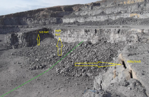
The study of instability aims at a side of a slope located in career of limestone LAFARGE, M'sila ALGERIA. The career is excavated as benches with 20 m in height, and 10 to 20 m in width. The depth of mine is 180 m (Figure 1).
Several visits made on site made it possible to observe:
-A longitudinal tensile crack about 2.5 m from the downstream side of the roadway.
-Circular break in plan affecting the road platform and destroying the ground floor side embankment over a length of 275m spread over 3 zones this limit is upstream of the slip.
Figure 1: Sliding of Lafarge quarry.

Tension modeling and stability of Chouf Amar career
The model of study is represent three layers of sol, the marl layer of 5 m thickness is situated between of two layers of limestone .Based on laboratory results, the properties of each soil type are associated with the layer that represents it on the geometric model. The following table summarizes these geotechnical parameters (Table 1).
Table 1: Material properties of soils used in numerical modelling.

Generation of the mesh
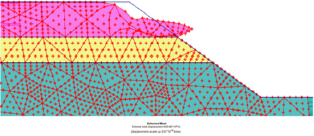
Figure 2: Mesh of the slope before sliding.

When a geometric model is fully defined and the properties of the materials are assigned to all layers, the geometry must be divided into finite elements in order to perform the finite element calculation. For more precise results we use a fine mesh (Figure 2).
The calculation
Depending on the case studied, the calculation is done in two phases. In the first one applies the gravity, one takes into account the hydraulic conditions and like type of calculation one chooses the plastic one, nevertheless in the second phase one makes the calculation of the factor of safety, where the points chosen for the calculation are at the peak talus, center, foot.
The deformed mesh: The deformed mesh is a representation of the mesh with the finite elements in its deformed state, superimposed on a representation of the undistorted geometry (Figure 3).
Figure 3: The deformed mesh.

The position of the critical circle
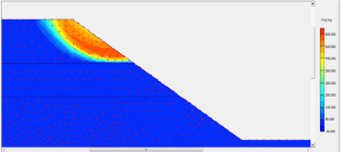
Figure 4: Incremental displacement.

The incremented displacements make it possible to know the position of the critical circle (Figure 4).
Results of Safety factor
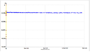
It is observed that the instability is well confirmed by the finite element method; the safety factor is of value of 0.981 and is less than 1. The latter is located in the upper part of the embankment, about 7 m deep from the slope.
Figure 5: Safety factor calculate in lafarge career.

the traction crack that moves 2.5 to 3 m away from the downstream side of the slope of career
-The most damaged area is also located on the downstream part of the crest of the slope.
-Instability is of circular slip type.
-The depth of the sliding circle is about 8m (Figure 5).
Conclusion
For a good analysis of the stability, it is preferable to use numerical methods, (in our case the MEF) for a better precision on the evaluation of slope stability.
Acknowledgement
The author would like to thank the staff of the laboratory natural resources and planning, University of Annaba, (Algeria). Also, a special thanks to Prof: A. Hafsaoui (Annaba University - Algeria) for her objective comments and corrections.
References
- Potts DM, Zdravkovic L (1999) Finite element analysis in geotechnical engineering: theory. Thomas Telford, London, UK.
- Brinkgreve RBJ, Baker HL (1991) Non-linear finite element analysis of safety factor. Proceedings of the 7th international conference on computer. Methods and advances in Geomechanics IACAMAG, Cairns, pp. 1117-1122.
- Cheng YM, Lansivaara T, Wei WB (2007) Two-dimensional slope stability analysis by limit equilibrium and strength reduction methods. Computers and Geotechnics 34(3): 137-150.
- Hammah R, Jacoub T, Corkum B, Curran J (2005) A comparison of finite element slope stability analysis with conventional limit equilibrium investigations. Rocscience.
- Duncan JM (1996) State of the art: Limit equilibrium and finite element analysis of slopes. Journal of Geotechnical Engineering 122 (7): 577-596.
- Griffiths DV, Lane PA (1999) Slope stability analysis by finite elements. Geotechnique 49(3): 387-403.
- Zhang K, Shi J, Yin Z (2010) Stability analysis of channel slope based on FEM strength reduction. Proceedings of the Twentieth International Offshore and Polar Engineering Conference pp.757-762.
- He B, Zhang H (2012) Stability analysis of slope based on finite element method. IJ Engineering and Manufacturing 3: 70-74.
© 2018 Saadoun Abderrazak, et al. This is an open access article distributed under the terms of the Creative Commons Attribution License , which permits unrestricted use, distribution, and build upon your work non-commercially.
 a Creative Commons Attribution 4.0 International License. Based on a work at www.crimsonpublishers.com.
Best viewed in


.jpg)


 Editorial Board Registrations
 Submit your Article
 Refer a Friend
 Advertise With Us
.jpg)


.jpg)


.bmp)
.jpg)
.png)
.jpg)


.jpg)


.png)

.png)


.png)


