- Submissions

Full Text
Aspects in Mining & Mineral Science
Application of Macro-Synthetic-Fiber-Reinforced Sprayed Concrete for Primary Lining Support on Highway Tunnel Project in Bosnia and Herzegovina
Dipl Ing Vedad Terzic* and Dipl Ing Reuf Kadric
Motorways of Federation of Bosnia and Herzegovina Ltd, Dubrovacka, Bosnia and Herzegovina
*Corresponding author: Dipl Ing Vedad Terzic, Motorways of Federation of Bosnia and Herzegovina Ltd, Dubrovacka, 71000 Sarajevo, Bosnia and Herzegovina
Submission: January 23, 2018; Published: March 14, 2018

ISSN: 2578-0255 Volume1 Issue3
Abstract
Background: The programmed death ligand or PDL-1 (also known as B7-H1) has been shown to inhibit tumor immunology and facilitate immune evasion. Although these mechanisms are well known in many cancers, recent evidence has suggested this function may also be active in oral cancers. To determine appropriate models to study this phenomenon, well-characterized oral cancer cell lines were screened to evaluate the presence and expression of PDL-1 or B7-H1.
Methods: Commercially available oral squamous cell carcinomas (SCC25, SCC15, CAL27) were used for this study. RNA was isolated and subsequently screened using validated primers specific for B7-H1/PDL-1. RNA was quantified and screened for purity prior to normalization and the RT-PCR screening procedure.
Results: mRNA was successfully isolated from each cell line and verified using spectrophotometric measurements and internal PCR control standards. Subsequent screening using validated primer sets revealed expression of B7-H1 in all oral cancer cell lines, with differential expression observed using the PDL-1 validated primer set. No expression was observed in the normal, non-cancerous oral gingival cell line examined.
Conclusion: These results demonstrated that the oral cancer cell lines evaluated expression mRNA which can be successfully screened using previously validated primers. However, because differential non-equivalent results were obtained when comparing the two validated primer sets, care should be taken to determine why the difference in specificity was observed and how this may affect selection and evaluation of appropriate screening tests for future clinical samples and isolates.
Summary
The application of macro synthetic fiber reinforced sprayed concrete is seen by many design engineers as the alternative to steel reinforced sprayed concrete. The first applications of macro synthetic fiber reinforced sprayed concrete in Bosnia and Herzegovina were applied during the construction of the Sarajevo By-pass Motorway. The Project included a Motorway tunnel-system of three (3) double tubed, two-lane tunnels receptively 860m, 2776m and 402m in length, passing through an extensive and diverse geology. In this work application of macro synthetic fiber reinforced sprayed concrete will be presented, giving an inside in the underground condition, the concrete testing, measurements and calculations. The aspects related to the excavation work-cycles and time savings applying fiber reinforced sprayed concrete in the primary lining will also be presented.
The Highway Tunnel Project
The Motorway Project is located on the route of the Pan European Corridor 5c: Budapest-Osijek-Ploce and is the most important Project for Bosnia and Herzegovina in the last decade. The construction works on the 20km long motorway section passing the capital city Sarajevo were significant for the city traffic itself.
The Project started in May 2012 and the construction time was 28months. The length of the subsection "Lepenica-Tarcin" (Figure 1) was approximately 10km and included a number of different structures, whilst the construction of tunnels T2, T3 and T4 was the most significant part of the project. Especially the construction of the Tunnel T3 (later renamed as "Tunnel 25th of November") with an average length of 2776m being potentially on the "critical path" The construction of Tunnel T3 on the subsection "Lepenica-Tarcin" will be the subject of this work [1].
Geometric elements of tunnel T3
Right tunnel tube length: 2802m;
Left tunnel tube length: 2743m;
Max. Altitude: 664.7m; max. Longitudinal gradient 3.59% at north portal;
The carriageway width is 7.0m, and consists of two lanes of 3.50m.
The tunnel height is 4, 70m.
Figure 1: Motorway Section.

Underground Conditions
The Underground conditions (geological formations) on the location of TUnnel T3 were diverse and complex. Three (3) basic types of rock were found (Sedimentary, Metamorphic and Magmatic rocks) [2]. The Metamorphic rocks were from Paleozoic and the Dolomites were from Devon. In-between two Magmatic layers of Quartz Porphyries were also found (Figure 2).
Figure 2: Longitudinal tunnel section.

Tunnel Excavation And Support
Tunnel excavation and support elements (Main Design of the Project)
In accordance to the Main Design documentation in the Project the excavation works were divided into three (3) phases. The top heading, bench and the invert arch excavation phase. In better underground conditions the excavation works were divided in top heading and bench phases only [3]. The Main Design defined rock categories, predicting the round lengths and defining support elements (system) for each of the rock category respectively (Table 1).
Table 1: Rock categories and support elements (systems) in accordance with the Main Design.
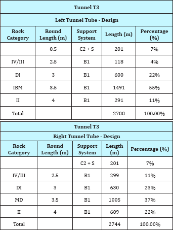
The following support elements were installed according to the rock mass categorization:
i. B1 - rock mass category
Sprayed concrete C 25/30, 10cm in thickness;
Reinforcement - Mesh Q189, 1 layer;
SN anchors 4m, 250kN
ii. C2+S - rock mass category
3cm thick layer of sprayed concrete and mesh Q131 at tunnel face;
Sprayed concrete C 25/30, 20 cm in thickness;
Steel arch TH21;
Reinforcement - Mesh Q189, 1 layer;
SN or IBO anchors 4m, 250kN;
Concrete invert arch
Tunnel T3 excavation works
At the early beginning of the Tunnel T3 Project it was obvious that the predicted rock mass categories given in the Main Design are different compared to the actual underground conditions on site. At the entrance portal and the tunnel precut it was identified that the Main Design was predicting 4th (IV) rock mass category and actually 5th (V) rock mass category was present. Consequently it was necessary to apply other support elements, demanding more time (require longer installation time) then predicted. Due to the underestimation of underground conditions inevitably delays in the excavation works in Tunnel 3 were going to occur. Only undertaking appropriate measures it was possible to mitigate delays and finish the Project within the expected program of work.
According to the geological predictions approximately two thirds of the Tunnel T3 was located either in dolomitic limestone (approx. 900m) or quartz-porphyric metamorphic rock (approx. 900m). In such underground conditions it was possible to modify the conventional support elements (systems) and apply fiber reinforced sprayed concrete instead of mesh reinforced sprayed concrete. It has been estimated that the changes in these support elements would probably save 2 to 3hours per round length (step of excavation) [4]. The length of the tunnel rock mass categories where fiber reinforced sprayed concrete could be used was estimated to be 1800m in length. Average round length (step of excavation) was estimated to be 2.5m.
Calculation
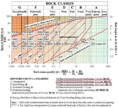
Figure 3: Updated Q-System (Grimstad and Barton, 1993).
1800m/2.5m = 720 steps
720 (steps) x (2-3hours-shorter installation time) =makes up to 1440 to 2160hours
(1440h-2160h)/24hours =60-90days
In order to implement this idea a 60m test field in Tunnel T3 was formed to compare the behavior of the support elements in real underground conditions. The behavior of mesh reinforced sprayed concrete (cross section 24.300-24.330; 30m) and fiber reinforced sprayed concrete (cross section from 24.330m to 24.360m ; 30 m)lining had to be tested. Measurement profiles were installed (measuring the movements in the primary lining for a period of time until the settlements stabilize) at 24.315m (cross section with mesh reinforced sprayed concrete) and 24.345m (cross section with fiber reinforced sprayed concrete).
Tunnel Support Systems Using Fiber Reinforced Sprayed Concrete
The updated Q-System
The relation between the rock-mass quality and the support elements (supporting system) using fiber reinforced sprayed concrete is defined by the updated Q-System by Grimstad and Barton (Figure 3). Identifying the rock-mass quality (Q) for certain rocks the supporting elements (system) can be predicted using the updated Q-System.
For the intended underground conditions in Tunnel T3 where fiber reinforced sprayed concrete could have been used, the rock- mass quality index was ranging between 1 and 10 (D-Poor, C-Fair, B-Good). Considering the Span or Height ratio (for ESR = 1) being10 the expected reinforcement categories 4, 5 and 6 would need energy absorption capacity between E=500-700J (Figure 4).
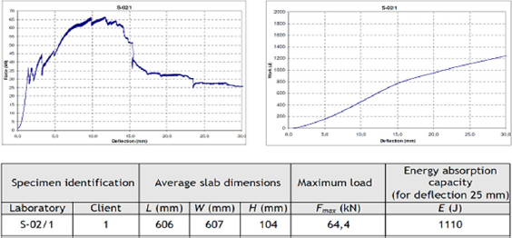
Figure 4: Plate test (EN 14485-5)-mesh reinforced sprayed concrete..
The test field of macro-syntheticfiber reinforced sprayed concretein tunnel T3
The interaction of the rock-mass and the tunnel primary lining could be observed during the construction, making real scale measurements. Measuring the displacements of the rock-mass the impact on the tunnel support elements could be observed in real time. According to the NATM concept, measurement profiles are installed systematically at characteristic sections along the tunnel. The aim of the monitoring is to predict and to prove the adequacy of the supporting system. This approach was also applied in the test field with the aim to confirm the adequacy of the fiber reinforced sprayed concrete lining in Tunnel T3. The back calculation analysis was used to determine the relevant mechanical characteristics of the rock-mass and to refine the support measures. The test field of a 60m section of the both mesh and fiber-reinforced sprayed concrete lining was installed to examine if the fiber reinforced sprayed concrete primary lining could be equally efficient as the conventional primary lining when used in similar geological conditions [5]. In particular the bending capacity had to be assessed this way. To quantify the efficiency of the fiber reinforced sprayed concrete primary lining, the results from the test section had to be compared with the results of the measurement profiles featuring the conventional primary lining for the same overburden, and very similar geological conditions.
The test setup
The test setup was as follows:
i. In to the already used sprayed concrete mixture 4kg of polypropylene fibers were added Properties of the "Bar chip 54"fibers: length 54mm; tensile strength 640MPa; Specific Gravity 0.90-0.92; Elastic modulus 10GPa; Number of fibers per kg 37,000
ii. Determination of energy absorption capacity-EFNARC plate test (EN 14485-5; 2006) mesh reinforced concrete samples
iii. Determination of energy absorption capacity-EFNARC plate test (EN 14485-5; 2006) macro-synthetic fiber reinforced sprayed concrete samples
iv. Back-calculation for the underground conditions and support measures installed at 24.315m (mesh reinforced sprayed concrete)
v. Measuring the profiles on cross sections at 24.315m (mesh reinforced sprayed concrete) and 24.345m (cross section- fiber reinforced sprayed concrete)
Results of the testing and measurements
Plate test-(EFNARC, EN 14485-5; 2006) mesh reinforced concrete (Figure 4)
Plate test - (EFNARC, EN 14485-5; 2006) fiber reinforced sprayed concrete (Figure 5)
Back calculation of the support elements at 24.315 (mesh reinforced lining): The estimation of geotechnical parameters was based on the geological mapping and data collected by the geologist on the site (RMR=47). The geotechnical parameters were assumed using the Hoek & Marinos [6] method taking into account all the relevant indicators of the rock mass behavior including the favorableness of the rock layering. Relevant parameters (τci=40 MPa, GSI=42, mi=10, D=0, 5, MR=500, γ= 0, 025 MN/m3, Tunnel Depth=65m) where analyzed using the software ("Roc Lab") to acquire Mohr-Coulomb strength parameters for numerical analysis (c=0, 274MPa; phi=42, 86deg; E=1744, 22MPa). After the back- calculation the following results were computed (Figure 6 & 7): The bending moments (Md, max=8, 78kNm/m) and axial forces (Nd, max=489, 80N/m) are plotted on the interaction diagrams (Figure 7) of the mesh reinforced sprayed concrete for the installed sprayed concrete C25/30 and reinforcement steel mesh type-Q 188. The predicted bending capacity of the primary lining in the B1 rock mass category should not exceed 20kNm/m.
Figure 5: Plate test (EN 14485-5)-fibre reinforced sprayed concrete.
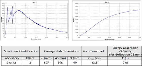
Figure 6: Computed results-displacements.
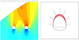
Figure 7:Computed results-interaction diagram.
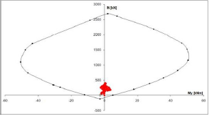
Figure 8: Movements in the primary lining-mesh reinforced sprayed concrete.
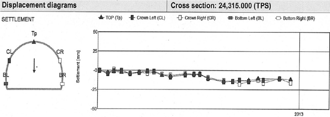
5.4.4.Measurement profiles on cross sections at 24.315m and 24.345m: Maximum displacement at 24.315m-mesh reinforced sprayed concrete: 11mm (Figure 8)
Maximum displacement at 24.345m-fiber reinforced sprayed concrete: 9mm (Figure 9)
Figure 9: Movements in the primary lining-mesh reinforced sprayed concrete.

Conclusion
The macro-synthetic fiber reinforced sprayed concrete samples have shown less energy absorption capacity in comparison with the mesh reinforced sprayed concrete samples determined by the EFNARC plate test (EN 14485-5; 2006). The required energy absorption capacity according to the updated Q-System rock classification by Grimstad & Barton [2] was between E=500-700J see (Figure 3) and the tested energy absorption capacity of tested specimens using macro-synthetic fiber in the test field was of an average of E=740J see (Figure 5). It could be concluded that the energy absorption capacity of the macro-synthetic fiber reinforced sprayed concrete was still of satisfactory capacity and could be applied for the support system in category B1.
The test filed results show a very good post cracking performance of the macro-synthetic fiber reinforced sprayed concrete at deflections of about 5mm. It was measured that the deflections of 5mm usually occur during the first hours after excavation.
Analyzing the energy absorption test results at the deflection of 5mm it can be concluded that both the mesh and fiber sprayed concrete capacity absorb almost the same force F=45kN see (Figure 4 & 5). Considering these results the fiber sprayed concrete provides more safety during the first hours of excavation due to simple installation.
Analyzing the results of the back calculation the Md, max=8,78kNm/m at the total displacement of 10mm is much more smaller compared to the predicted bending capacity of 20kNm/m in the primary lining for B1 rock mass according to ONORM B2203. The measurement profiles on cross sections at 24.315m and 24.345m showed almost the same deflections for both the mesh and fiber sprayed concrete primary lining. So it can be concluded that the fiber sprayed concrete lining can be equally efficient.
Table 2: Rock mass categorization and executed support systems.
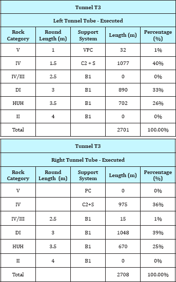
The in-situ identified geological rock mass categories and the applied support systems are shown in Table 2. Comparing the geological rock mass categories from the Main Design (Table 1) and the categories identified during the excavation obviously shows that the share of 4th (IV) rock category was increased and on the other hand, the shares of 2nd (II) and 3th (III) geological rock mass categories were reduced.
After all, in TUnnel T3 almost 1600m of fiber reinforced sprayed concrete was applied. The net saving time using macro synthetic fiber in the sprayed concrete lining was 70days. This fully compensated the lost time for the increased length of 4th (IV) rock category that was not predicted by the Main Design. The Project was successful accomplished on time, with no delays. The application of fiber sprayed concrete using engineering know-how and experience played a dominant role in this successful construction project. Macro synthetic fiber sprayed concrete and fiber sprayed concrete in general should be considered as a powerful tool in tunnel engineering projects.
References
- Alsaab HO, Sau S, Alzhrani R, Tatiparti K, Bhise K, et al. (2017) PD-1 and PD-L1 checkpoint signaling inhibition for cancer immunotherapy: mechanism, combinations, and clinical outcome. Front Pharmacol 8: 561.
- Diesendruck Y, Benhar I (2017) Novel immune check point inhibiting antibodies in cancer therapy-opportunities and challenges. Drug Resist Updat 30: 39-47.
- Mishra A (2017) PD-1/PD-L1 biology and immunotherapy in HPV- positive oral cancers. Future Oncol doi: 10.2217/fon-2017-0115.
- Hoesli R, Birkeland AC, Rosko AJ, Issa M, Chow KL, et al. (2018) Proportion of CD4 and CD8 tumor infiltrating lymphocytes predicts survival in persistent/recurrent laryngeal squamous cell carcinoma. Oral Oncol 77: 83-89.
- Heymann MF, Lezot F, Heymann D (2017) The contribution of immune infiltrates and the local microenvironment in the pathogenesis of osteosarcoma. Cell Immunol pii: S0008-8749(17)30189-2.
- Spurrell EL, Lockley M (2014) Adaptive immunity in cancer immunology and therapeutics. Ecancermedicalscience 8: 441.
- Hirai M, Kitahara H, Kobayashi Y, Kato K, Bou-Gharios G, et al. (2017) Regulation of PD-L1 expression in a high-grade invasive human oral squamous cell carcinoma microenvironment. Int J Oncol 50(1): 41-48.
- Lanzel EA, Paula Gomez Hernandez M, Bates AM, Treinen CN, Starman EE, et al. (2016) Predicting PD-L1 expression on human cancer cells using next-generation sequencing information in computational simulation models. Cancer Immunol Immunother 65(12): 1511-1522.
- Wu L, Deng WW, Yu GT, Mao L, Bu LL, et al. (2016) B7-H4 expression indicates poor prognosis of oral squamous cell carcinoma. Cancer Immunol Immunother 65(9): 1035-1045.
- Moore EC, Cash HA, Caruso AM, Uppaluri R, Hodge JW, et al. (2016) Enhanced tumor control with combination mTOR and PD-L1 inhibition in syngeneic oral cavity cancers. Cancer Immunol Res 4(7): 611-620.
- Yu GT, Bu LL, Huang CF, Zhang WF, Chen WJ, et al. (2015) PD-1 blockade attenuates immunosuppressive myeloid cells due to inhibition of CD47/ SIRPa axis in HPV negative head and neck squamous cell carcinoma. Oncotarget 6(39): 42067-42080.
- Osafi J, Hejazi A, Stutz DD, Keiserman MA, Bergman CJ, et al. (2014) Differential effects of 1,25-dihydroxyvitamin D3 on oral squamous cell carcinomas in vitro. J Diet Suppl 11(2): 145-154.
- Moody M, Le O, Rickert M, Manuele J, Chang S, et al. (2012) Folic acid supplementation increases survival and modulates high risk HPV- induced phenotypes in oral squamous cell carcinoma cells and correlates with p53 mRNA transcriptional down-regulation. Cancer Cell Int 12: 10.
- Tsushima F, Tanaka K, Otsuki N, Youngnak P, Iwai H, et al. (2006) Predominant expression of B7-H1 and its immunoregulatory roles in oral squamous cell carcinoma. Oral Oncol 42(3): 268-274.
- Concha-Benavente F, Srivastava RM, Trivedi S, Lei Y, Chandran U, et al. (2016) Identification of the cell-intrinsic and -extrinsic pathways downstream of EGFR and IFNy that induce PD-L1 expression in head and neck cancer. Cancer Res 76(5): 1031-1043.
© 2018 Dipl Ing Vedad Terzic, et al. This is an open access article distributed under the terms of the Creative Commons Attribution License , which permits unrestricted use, distribution, and build upon your work non-commercially.
 a Creative Commons Attribution 4.0 International License. Based on a work at www.crimsonpublishers.com.
Best viewed in


.jpg)


 Editorial Board Registrations
 Submit your Article
 Refer a Friend
 Advertise With Us
.jpg)


.jpg)


.bmp)
.jpg)
.png)
.jpg)


.jpg)


.png)

.png)


.png)


