
- About Us
- Information
-

The Author ensures that the research has been conducted responsibly and ethically with adherence to all relevant regulations. read more..
- For Authors
- For Reviewer
- Manuscript Guidelines
- Membership
- Publication Ethics
-
- Journals
- Reprints
- e-Books
- Videos
- Policies
- Contact Us
 COVID-19
- Submissions


Full Text
Aspects in Mining & Mineral Science
The Effect of Bed Thickness and Cooling Time on the Rate of Copper Slag Cooling, Case Study: Khatoonabad Copper Smelter Plant
Esmaeil Rahimi1 and Neda Mohaghegh2*
1Department of Mining Engineering, Islamic Azad University- South Tehran Branch, Iran
2Department of Chemistry, Sharif University of Technology, Iran
*Corresponding author: Neda Mohaghegh, Department of Chemistry, Sharif University of Technology, Azadi Ave, Tehran
Submission: January 30, 2018; Published: February 20, 2018

ISSN: 2578-0255 Volume1 Issue2
Abstract
Within the past few decades, slags are remarked as the wastes polluting the environment. Nowadays, they are not only considered the waste but also regarded as valuable resources of base metals. Slags are treated with various methods and the slag cooling rate highly affects the success of such treating methods and metal recovery. The current essay scrutinizes one of the methods controlling the cooling rate due to the influence of cooling rate on chemical composition and slag treating. Thus, the slow cooling process of electric furnace slag is simulated in a small ditch through a practical experiment in Khatoonabad smelter plant. Then, the thermal diffusivity of copper slag is calculated based on the results of the experiment. Furthermore, the effect of time and bed thickness on cooling rate is analyzed through the heat equation development and the calculated thermal diffusivity. Results indicate that the increase of slag thickness reduces its cooling rate. Moreover, the cooling rate of the slag reveals a decreasing trend during the experiment.
Keywords: Copper slags: Base metals; Cooling rate; Bed thickness; Thermal diffusivity
Introduction
Previously, copper slag is counted as a waste of pyrometallurgical processes and it is necessary to dispose them to prevent environmental pollution [1,2]. Such slags are an inevitable product of most copper smelting furnaces including Reverbatory, Flash and Convertors [3-5]. Copper slags aren't considered the waste because of production capacity, high copper grade [6] and also specific mechanical and strength properties [7,8]. The studies reveal that in case slags are properly mixed with building material, they not only increase the tensile strength [9] but also enhance the durability of building material [10]. Moreover, a lot of research has been conducted to practice slags in producing cement and various industrial mortars [11-14]. Their other important industrial application is in constructing roads [15]; however, Lind has reported that they make environmental pollution [16]. This is while, the development of mineral processing studies demonstrates that recovering base metals from slag reduces environmental pollution and it is economically beneficial [17,18]. This issue is more remarkable in copper slag than other ones considering the more valuable metals and specific metallurgical structure.
Slags produced by pyrometallurgical methods contain different minerals and chemical composition. The electric furnace (EF) slag includes low grade copper and high ferrous [4,7]. Notably, copper grade are higher in Convertor furnace (CF) slags [19]. In addition, the slags of Reverbatory furnaces have high grade copper (1-3)% and SiO2 [20,21]. On the other hand, slags produced by the direct blister method contain different mineralogy including various oxide minerals as well as primary and secondary sulfides [22-24]. According to the differences of chemical compositions of various slags, different processing methods are put into practice to recover copper. Flotation [25-27], hydrometallurgical methods [28-32] and copper slags returning to the EF [33] are applied in copper recovery from the slags due to their type of chemical composition.
From the other point of view, researches demonstrate that chemical compositions and mechanical strength of slags completely rely on their production method and cooling rate [34]. This is due to the chemical-physical properties of slags [35]. High cooling rate leads to producing slags with amorphous structures. In fact, studies show that the floatation method is not a suitable one to process such minerals. So, it is very significant to control the rate of slag cooling in order to get better results from flotation method. There are different methods controlling the speed of slag cooling. Granulation in water, ladle cooling and cooling bed result in a different cooling rate for slags [36]. Slag cooling in bed is counted as one of the slowest method of cooling. Besides chemical properties and slag thermal diffusivity, there are some other parameters affecting the rate of slag cooling in bed such as bed thickness and design. As a matter of fact the cooling speed in this bed is controlled by the changes of its thickness. Due to boundary conditions of the designed bed, it is very important to specify the cooling rate in different depth of slags. Consequently, a practical experiment is conducted to simulate the process of slag cooling in bed in the slag of the Khatoonabad smelter plant. Then, the actual thermal diffusivity of slag, which has not been determined, yet, is calculated. Holistically, the rate of slag cooling is evaluated as a function of cooling time and bed thickness.
Experimental
Problem definition
Figure 1: The slags production processes and their treating methods.

Copper slags are produced by different smelting processes and treated through pyrometallurgical and hydrometallurgical methods and they will be returned to the production process. The slags production processes and their treating methods are illustrated in Figure 1. As observed in Figure 1, selecting slag treatment method relies on the mineralogy and chemical-physical properties of slag. Thus, controlling the slag cooling rate is technically and economically significant. Several slag cooling methods are applied to control the rate. The most important method is slag cooling in bed. In this regard, the important points are designing the bed and choosing an appropriate thickness. Hence, the amount of heat transferred from slag and cooling rate is considered a function of the slag thickness and they will be analyzed.
Materials and Methods
Table 1: The chemical composition and mineralogica! analysis of the fast cooled EF slag.

The EF slag of the Khatoonabad smelter plant is applied to simulate the slag cooling process in cooling bed. Chemical composition and mineralogical analysis of the fast cooled slag is displayed as Table 1. The EF slag temperature is 1410 °C. It is predicted that this degree is reduced approximately up to 40 °C in ladles of the slag pot carrier while sending to the experiment location. The production rate of this slag is 2500 tons per day. It can be considered an important source of copper due to its grade.
Cooling bed
A ditch is excavated as an approximate rectangle shape in 1180cm and 410cm dimensions to do the slag cooling experiment in bed. The bed depth is estimated 60 cm which it can be filled by smelter slags by 40cm. Crushed slags in one inch are practiced to decrease heat transfer from earth to slag and reduce slag cohesion in bed. The ditch capacity is designed 17m3. A steel ruler is applied to determine the bed thickness in ditch wall. Since rainfall affects the test results, the area's climate should be precisely contemplated.
Instruments
The instruments used in experiment include two temperature indicators (No.13FMM0025, Hainan type). These two indicators are connected to thermocouple (S series) with an opal cover. Figure 2a shows a schematic of temperature indicators. Furthermore, thermocouples are covered by wool glass to omit radiation effects on them. Figure 2b illustrates the coverage and thermocouples. Sensors are installed in two locations to simulate the slag cooling process shown in Figure 3a. The first sensor (A) is almost placed at the ditch center 20cm away from the ground. This place marks the least heat transferring to around. The second sensor (B) is placed at the corner of ditch 5cm away from the ground. This is location scores the most connection with the ground and it should indicate the highest cooling rate. Figure 3b features out the ditch loading by ladle and slag pot carrier.
Figure 2: a) Temperature indicators used in experiment, b) The test thermocouples and coverage.

Figure 3: a: The location of the thermocouples in test, b: Slag loading in designed ditch.

Results and Discussion
Conduction simulation
Figure 4: a) The temperatures curves measured by A and B sensors, b) The heat variation in different depths of slag.

Figure 4a depicts the temperatures measured by A and B sensors. As expected, as time drags on, this temperature is exponentially declined. The moment right after the experiment, the temperatures of different spots of slag to depth are calculated through changing the sensor location in slag depth. This is done by changing the angle of steel structure over the ditch. The temperature profile is depicted by sensor A with 5 points in the intervals of 8cm. Figure 4b reveals the heat profile in various depths of the sensor.
Diffusion qquation
The general heat transfer equation is defined as relation 1 for this slag. The boundary conditions are described as below according to data gathering.
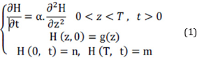
Where, H is the temperature, t is the time and z indicates the slag depth. a is the thermal diffusivity and T introduces the maximum thickness of the slag in bed. n and m are also the temperature of the slag in contact with ground and air, respectively. g(z) is shown the temperature function of slag rather than depth variations.
The separation of variables method can be used to solve the equation described in relation 1.
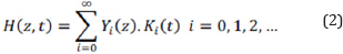
The heat transfer equation and related coefficients can be determined by the Fourier cosine series as below:
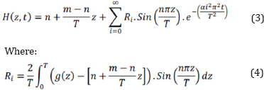
Moreover, g(z) is numerically considered in the equations of heat transferring to increase the exactness of calculations. As shown in relation 3, the thermal diffusivity is unknown.
Calculation of thermal diffusivity
The determination of the thermal diffusivity is essential to specify the heat profile to time and slag thickness. Thus, the difference between the real data ofthe experiment and the outcomes of the thermal equations should be minimized to calculate the thermal diffusivity. Due to high contact surface, the data of sensor B in equation 3 will be the most conservative results and lead to the highest cooling rate. In conclusion, the following relation:
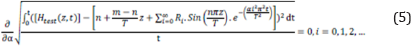
The amounts t=222180(s), n=18, m=24, T=40(cm), z=5(cm) are considered in equation 5 according to the experiments. This equation is solved by simulating a numerical model and Matlab programming. Thus, the thermal diffusivity is calculated as 0.00242cm2/sec.
Figure 5: Slag heat profile versus distance from ditch bed in different time.

Figure 5 illustrates the simulation of slag heat profile by 40cm thickness in different time and the depths of slag. As predicted, the temperature will be at its highest degree at bed center and as the experiment time drags on, the slag temperature is decreased.
Effect of bed thickness on cooling rate
The following simulation is done to analyze the effect of slag thickness on the cooling rate. Respectively, the effect ofslag thickness on the cooling rate is calculated in different intervals from the bed ground through the calculated thermal diffusivity (Figure 6a). This graph is presented at t=1s after the test started and it illustrates the highest cooling rate at this time. As a whole, the changes of slag cooling rate versus the time are studied in Figure 6b. In this graph, the slag thickness is considered 40cm similar to the experiment and the cooling rate is calculated in intervals of 1, 10 and 20cm from the bed ground (z). As observed in Figure 6a, the increase of slag thickness reduces its cooling rate. However, this rate varies in different intervals from the bed ground. Figure 6b indicates that the slag cooling rate is reduced during the experiment. Considerably, the cooling reduction rate is more in boundary conditions.
Figure 6: a) The effect of slag thickness on the cooling rate in different intervals from the bed ground (z), b) The slag cooling rate variation versus experiment time in different interval from the bed (z).

Conclusion
The cooling rate leads to various chemical composition and mineralogy of copper slags. As the cooling rate is changed, the processing methods of copper slags are changed, too. One of the most applicable methods of slow cooling method of slag is cooling in bed. The results of the current research are obtained from a practical experiment. The slag thermal diffusivity is calculated by simulating bed conditions. It is also demonstrated that the center has the highest rate of slag temperature and as it gets closer to the boundary conditions of the bed the temperature is decreased. From another point of view, the simulation of slag cooling process on the designed bed specified that as the slag thickness and the cooling time increase, its cooling rate is reduced. This is while; this reduction rate will vary in different intervals from the bed ground.
Acknowledgement
The authors are grateful to Canymes Company as the general contractor of Khatoonabad smelter for providing EF slag sample and related information. Also, we gratefully thank the University Language Center, especially Mrs. Azarme, for her cooperation in reviewing and editing this paper.
References
- Manz M, Castro LJ (1997) The environmental hazard caused by smelter slags from the Sta. Maria de la Paz mining district in Mexico. Environ Pollut 98(1): 7-13.
- Sánchez M, Sudbury M (2013) Physicochemical characterization of copper slag and alternatives of friendly environmental management. Journal of Mining and Metallurgy B 49(2): 161-168.
- Demetrio S, Ahumada J, Duran MA, Mast E, Rojas U, Sanhueza J, et al. (2000) Slag cleaning the Chilean Copper Smelter Experience. Jornal of Metals 52(8): 20-25.
- Davenport WG, King M, Schlesinger M, Biswas AK (2002) Extractive Metallurgy of Copper Elsevier Science Ltd, Oxford, UK.
- Moskalyk RR, Alfantazi AM (2003) Review of copper pyrometallurgical practice: today and tomorrow. Minerals Engineering 16(10): 893-919.
- Jalkanen H, Vehvilainen J, Poijarvi J (2003) Copper in solidified copper smelter slags. Scandinavian Journal of Metallurgy 32(2): 65-70.
- Gorai B, Jana RK, Premchand (2003) Characteristics and utilisation of copper slag-a review. Resources, Conservation and Recycling 39(4): 299-313.
- Najimi M, Pourkhorshidi AR (2011) Properties of concrete containing copper slag waste. Magazine of Concrete Research 63(8): 605 -615.
- Al-Jabri KH, Al-Saidy A, Taha R (2011) Effect of copper slag as a fine aggregate on the properties of cement mortars and concrete. Construction and Building Materials 25(2): 933-938.
- Osborne GJ (1999) Durability of Portland blast-furnace slag cement concrete. Cement and Concrete Composites 21(1): 11-21.
- Roy DM, ldorn GM (1982) Hydration, structure, and properties of blast furnace slag cements, mortars, and concrete. Journal Proceedings of American concrete institute 79(6): 444-457.
- Moura WA, Gonsalves JP, Lima MBL (2007) Copper slag waste as a supplementary cementing material to concrete. Journal of Materials Science 42(7): 2226-2230.
- Shi C, Meyer Ch, Behnood A (2008) Utilization of copper slag in cement and concrete. Resources, Conservation and Recycling 52(10): 11151120.
- Tsakiridis PE, Papadimitriou GD, Tsivilis C, Koroneos C (2008) Utilization of steel slag for Portland cement clinker production. Journal of Hazardous Materials 152(2): 805-811.
- Lavanya C, Sreerama Rao A, Darga Kumar N (2011) A review on utilization of copper slag in geotechnical applications. Proceedings of Indian Geotechnical Conference. pp. H-212.
- Lind BB, Fallman AM, Larsson LB (2001) Environmental impact of ferrochrome slag in road construction. Waste Management 21(3): 255264.
- Proctor DM, Fehling KA, Shay EC, Wittenborn JL, Green JJ, et al. (2000) Physical and chemical characteristics of blast furnace, basic oxygen furnace, and electric arc furnace steel industry slags. Environ Sci Technol 34(8): 1576-1582.
- Baghalha M, Papangelakis VG, Curlook W (2007) Factors affecting the leachability of Ni/Co/Cu slags at high temperature. Hydrometallurgy 85(1): 42-52.
- Arslan C, Arslan F (2002) Recovery of copper, cobalt, and zinc from copper smelter and converter slags. Hydrometallurgy 67(1-3): 1-7.
- Kojo IV, Jokilaakso A, Hanniala P (2000) Flash smelting and converting furnaces: A 50 year retrospect. JOM 52(2): 57-61.
- Bo L, Hua W, Jian-hang H, Lei L (2009) Progress in recovery technology of valuable metals from copper slag. Mining and Metallurgy.
- Victorovich GS, Bell MC, Diaz CM, Bell JAE (1987) Direct production of copper. JOM 39(9): 42-46.
- Rogoz K, Kucharski M (2010) The rate of metal oxygen reduction from the slag of the direct-to-blister flash smelting process. Archives of Metallurgy and Materials 55(1): 317-323.
- Makinen JK, Jafs GA (2013) Production of matte, white metal, and blister copper by flash furnace. JOM 34(6): 54-59.
- Roa G, Nayak (1992) Flotation of copper from convertor slags. Journal of Mine, Metal & Fuels 40: 3-4.
- Sarrafi A, Rahmati B, Hassani H, Shirazi H (2004) Recovery of copper from reverberatory furnace slag by flotation. Minerals Engineering 17(3): 457-459.
- Guo YH, Dai HX, Yang JL (2013) Research of the Complex Copper Slag Flotation Experiment. Advanced Materials Research 734: 972-976.
- Altundogan H, Boyrazli M, Tumen F (2004) A study on the sulphuric acid leaching of copper converter slag in the presence of dichromate. Minerals Engineering 17(3): 465-467.
- Oliazadeh M, Massinaie M, Seyed Bagheri M, Shahverdi AR (2006) Recovery of copper from melting furnaces dust by microorganisms. Minerals Engineering 19(2): 209-210.
- Carranza F, Romero R, Mazuelos A, Iglesias N, Forcat O (2009) Biorecovery of copper from converter slags: Slags characterization and exploratory ferric leaching tests. Hydrometallurgy 97(1-2): 39-45.
- Yang Z, Rui-lin M, Wang-dong N, Hui W (2010) Selective leaching of base metals from copper smelter slag. Hydrometallurgy 103(1-4): 25-29.
- Chen MS, Han ZR, Wang LZ (2011) Recovery of Valuable Metals from Copper Slag by Hydrometallurgy. Advanced Materials Research 402: 35-40.
- Herreros O, Quiroz R, Manzano E, Bou C, Vinals J (1998) Copper extraction from reverberatory and flash furnace slags by chlorine leaching. Hydrometallurgy 49(1-2): 87-101.
- Tshiongo N, Mbaya RK, Maweja K, Tshabalala L (2010) Effect of cooling rate on base metals recovery from copper matte smelting slags. World Academy of Science, Engineering and Technology 70: 273-277.
- Tossavainen M, Engstrom F, Yang Q, Menad N, Larsson LM, et al. (2007) Characteristics of steel slag under different cooling conditions. Waste Management 27(10): 1335-1344.
- Loncnar M, Zupan M, Bukovec P, Jakli A (2009) The effect of water cooling on the leaching behavior of eaf slag from stainless steel production. Materials and technology 43(6): 315-321.
© 2018 Neda Mohaghegh. This is an open access article distributed under the terms of the Creative Commons Attribution License , which permits unrestricted use, distribution, and build upon your work non-commercially.
Editor In Chief


.jpg)


Signup for Newsletter

Quick Links
 Editorial Board Registrations
 Submit your Article
 Refer a Friend
 Advertise With Us
Our Recent Edition

.jpg)


Top Editors


.jpg)


.bmp)
.jpg)
.png)
.jpg)


.jpg)


.png)

.png)


.png)


Financial Support

Sponsors

Latest e-Books

Latest Video

 a Creative Commons Attribution 4.0 International License. Based on a work at www.crimsonpublishers.com.
Best viewed in
a Creative Commons Attribution 4.0 International License. Based on a work at www.crimsonpublishers.com.
Best viewed in