- Submissions

Full Text
Aspects in Mining & Mineral Science
To Priority the Success Factors in the Design of Progressive Die by DFSS Methodology
Mozhgan Nozari, Amir Abbas Shojaie* and Sadigh Raissi
School of Industrial Engineering, Islamic Azad University, South Tehran Branch, Tehran, Iran
*Corresponding author: Amir Abbas Shojaie, School of Industrial Engineering, Islamic Azad University, South Tehran Branch, Tehran, Iran
Submission: January 11, 2018; Published: February 09, 2018

ISSN: 2578-0255 Volume1 Issue1
Abstract
As the industrial era progressed, the need for mass production is more sensed. Progressive die is widely used for mass production of sheet metal components due to its high productivity, high precision and relatively economic cost in terms of per piece of product. Progressive dies perform a series of fundamental cutting and forming operations typically on continuous sheet metal strip, or coil, stock. These operations are performed simultaneously at two or more stations during each press stroke as the strip progresses through the die to produce a part. Design of progressive die is a complex and highly specialized procedure, so designer progressive die must have a high level of knowledge on the part that can only be achieved through years of practical experience.
Checking the design features of sheet metal parts, design of strip-layout, selection of die components, selection of materials for die components; and modelling of die components and die assembly are major activities for designing a progressive die. The traditional methods of carrying out these tasks require expertise and are largely manual and therefore tedious, time consuming and error-prone. The quality of die design depends to a large extent on the designer's skill, experience and knowledge. This research attempts to study and priority the designing stages of progressive die by DFSS methodology (IDOV model). By focusing on the important stages, we can reduce the cost, the time of delivery and increase the quality and obtain the success factors.
Keywords: Designing progressive die; Design for Six-Sigma (DFSS); QFD; AHP; ANP
Introduction
Now a day's a very large variety of sheet metal forming processes are used in modern sheet metal product manufacturing company. Many of these sheet metal forming processes are used in making the parts of aircraft, automobile, ship, and other products, by using complex equipment derived from the latest discoveries. With the ever increasing knowledge of science and technology, future deformation processes promise to be even more intricate to meet the need for high productivity, cheap price, and greater accuracy. However, for the unique advantages, the more sophisticated deformation processes of today have not replaced the need for basic sheet metal forming processes and dies [1,2]. Sheet metal stamping dies are used for both serial and mass production. Their characteristics are: high productivity, optimal material usage, easy servicing of machines, not required skilled operator, and economic advantage. Parts made from sheet metal have many attractive qualities: good accuracy of dimension, ample strength, light weight, and a broad range size is possible to manufacture [2,3].
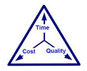
In today's global market, there is constantly increasing pressure to make products more quickly, with more quality, at the lowest possible cost, therefore Fast, Good and Cheap. Here Fast refers to the time required to deliver the product, good is the quality of the final product, and cheap refers to the total cost of designing and building the product. This triangle reflects the fact that the three properties of a project are interrelated. In the end, they must need a system of methods and activities for developing these items. So they must use the methodology for decreasing the deficiencies. One of the best methodologies is Six Sigma. The Six Sigma approach is primarily a methodology for improving the capability of business processes by using statistical methods to identify and decrease or eliminate process variation. Its goal is reduction of defects and improvements in profits, employee morale and product quality (Figure 1).
SS is a well-known quality improvement methodology used to reduce quality problems with a goal of improving quality such that production can be controlled within six standard deviations from the mean. The impact of SS on the world of quality control was so significant that its philosophy spread backwards through the manufacturing chain to the product design phase [4]. Design for Six Sigma can be seen as a subset of Six Sigma focusing on preventing problems, instead of just fixing them Hober, Mazur [5]. In this paper we used DFSS for Progressive die designing to identify the key stage in designing steps.
Figure 1: Quality Triangle.
Types of Die Construction
Stamping dies are classified by the type of construction of the dies are compound die, combination die and progressive die.
Compound die
Compound dies produce very accurate parts, but their production rate is quite slow. These dies consist of a single station where the part is most often blanked out and either formed, embossed, pierced, or otherwise adjusted in a single stroke of the press.
Combination dies
Combination die combine at least two operations during each stroke of the press. Some shops, however, are making a distinction between the two types calling any cutting and forming die a combination die, while the compound die is considered only a cutting die.
Progressive die
A progressive die performs a series of fundamental sheet metal operations at two or more stations during each press stroke in order to develop a work piece as the strip stock moves through the die. The work piece on progressive dies travels from one station to another, with separate operations being performed at each station. Usually the work piece is retained in the stroke until it reaches the final station, which cuts off the finished piece. All stations work simultaneously at different points along the work strip, which advances on station at each stroke of ram. Thus a complete part is produced with each stroke. Progressive dies generally include blanking and piercing operations but a complicated progressive die can do the operation of bending, forming, curling and heading also. Each workstation performs one or more distinct die operation, but the strip must move from the first through each succeeding station to fabricate a complete part [2,3]. As the metal strip is moved through the drawing process, it is exposed to a series of progressive die stations, each one changing the metal configuration left on the metal by the previous station. Therefore, the metal work piece is created in a series of stamping stages.
A large number of parts are deformed by stamping in many advanced industries such as automobile, electronic, airplane and etc. Progressive die are used in order to improve the quality and the efficiency of products. Progressive die, comparing with simple press tool, has the advantages of high quality and efficiency of product, which is especially suitable for high volume mass production in a short delivery time.
The characteristics of the progressive die stamping
i. Progressive die is a multi-task sequence die, a mold, including punching, bending and stretching process, with high productivity;
ii. Progressive die operations with full security;
iii. Automation;
iv. Can use high-speed punch press for production;
v. Can reduce the numbers of punches, the plant area, reducing transport and storage of semi-finished products occupy;
Basic requirements of progressive die parts
i. Smaller parts
ii. High volume
iii. Material thickness is thinner
iv. Material relatively soft
v. Shape is more complex
vi. Materials: strips of Aluminium, copper, brass, stainless steel, carbon steel, mild steel, cold roll steel, etc.
Die block, die gages, stripper plate, punch plate, back plate, punches, pilots, die-set and fasteners are major components of a progressive die.
Purpose of this Research
As a mention, the three most common primary objectives in a project are lowest cost, highest quality and shortest time. In the progressive die project, there are several variables for The time ,cost and quality constraint .So The major research objectives are: (1)to determine the influence of these three constraints (time ,cost and quality) for a progressive die by AHP and ANP; (2) to verify the stage of designing and manufacturing progressive die; (3) to determine the influence of these stages on constraints (time, cost and quality) by DFSS; (4) to priority these stages by DFSS and QFD.
In this paper, these constraints are applied:
Quality Constraint
i. Quality of the products produced by progressive die
ii. Quality of progressive die Cost Constraint
i. Reducing cost of the products produced by progressive die
ii. Reducing cost of designing and manufacturing progressive die
Time Constraint
Time of delivery
They are considered as VOC (Voice of Customer).
Previous and Related Work
A number of researchers have tried to develop computer aided systems for progressive die [6]. For example, Murikama & Shirai [7] developed a CAD/CAM system which is capable of generating assembly and dimensioned part drawings as the final out put but the strip and die layouts have to be done manually by the designer Researchers at National University of Singapore and Institute of High Performance Computing, Singapore also reported to have developed an integrated modeling and process planning system for planning bending operations of progressive dies. Sima et al. [8] carried out the study on the development of centre carrier type progressive die for U-bending part process.
Ghatrehnaby & Arezoo [9] reported to develop an automated nesting and piloting system for progressive dies. Some researchers reported to have developed intelligent CAD systems for Progressive die. For example, Duffy & Sun [10] developed acknowledge- based system for the design of progressive stamping dies using a feature-based approach. Lee et al. [11] developed an intelligent knowledge-based process planning system for the manufacture of progressive die plates. Cheok et al. [12] reported to have developed an intelligent planning aid for progressive die design using PC development tools. Ismail et al. [13] have also worked on expert systems for progressive piercing and blanking die design. Zheng et al. [14] have developed intelligent system for automobile panels. Some of researchers have worked on material. The design of die components and their material selection are major activities during progressive die design [15] .The selection of proper materials for progressive die components essentially increases the die life and hence reduces the cost of production of sheet metal parts [15,16].
The Essential Tools
DFSS
Design for Six Sigma is used to design or redesign a product or service is. DFSS considered as a systematic management technique Brue & Launsby [17] that optimizes product, service, and procedure design through management tools, training sections, and evaluation methodologies such that customers' expectation and quality criteria can be reached.
The methodology utilized by DFSS is similar to that used during implementation of Six Sigma. Although there are a number of variations in the methodology used to carry out DFSS.
Table 1: Different Types of Methodologies for DFSS.

Table 2: IDOV details - Critical-to-X factors and key measurable.
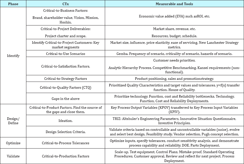
Table 1 shows the Different Types of Methodologies for DFSS, Yihai He et al. [24] and the details of IDOV methodology illustrates in Table 2. Hober, Mazur [5] the basic concept of DFSS is to clearly understand the customer's requirements and translate them to the critical to quality (CTQ) characteristics of the product. Quality function deployment (QFD) is a natural part of most DFSS strategies.
QFD
QFD is a systematic approach for transitioning voice of the customer (VOC) into design requirements. QFD is a valuable tool for ensuring that customer needs drive the entire design development process. QFD is a planning tool that allows the flow-down of high- level customer needs and wants through to design parameters and then to process variables critical to fulfilling the high-level needs. By following the QFD methodology, relationships are explored between quality characteristics expressed by customers and substitute quality requirements expressed in engineering terms [25].
Figure 2: House of Quality.
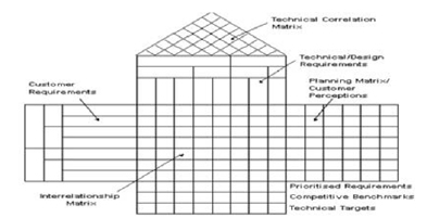
The essential part of the QFD is House of Quality. HOQ is a matrix, diagram, resembling a house. It translates customer requirements, based on marketing research and benchmarking data, into an appropriate number of engineering targets to be met by a new product design. According to Hauser & Clausing [5], it is a kind of conceptual map that provides the means for inter functional planning and communication." There are many different forms of the House of Quality, but its ability to be adapted to the requirements of a particular problem make it a very strong and reliable system to use. Its general format is made up of six major components. These include customer requirements, technical requirements, a planning matrix, an interrelationship matrix, a technical correlation matrix, and a technical priorities/benchmarks and targets section. To find out the key factor in the HOQ, used the Analytic Network Process (ANP) method for calculating the customer important in this research, and used the Analytic Hierarchy Process (AHP) method for valitaditing the result (Figure 2).
AHP
The AHP, developed by Saaty [26], has been studied extensively and used in almost all the applications related with multiple criteria decision making (MCDM) in the last 20 years. The AHP consists of three main operations, including hierarchy construction, priority analysis, and consistency verification. First of all, the decision makers need to break down complex multiple criteria decision problems into its component parts of which every possible attributes are arranged into multiple hierarchical levels. After that, the decision makers have to compare each cluster in the same level in a pair wise fashion based on their own experience and knowledge. For instance, every two criteria in the second level are compared at each time with respect to the goal, whereas every two attributes of the same criteria in the third level are compared at a time with respect to the corresponding criterion. Since the comparisons are carried out through personal or subjective judgments, some degree of inconsistency may be occurred. To guarantee the judgments are consistent, the final operation called consistency verification, which is regarded as one of the most advantages of the AHP, is incorporated in order to measure the degree of consistency among the pair wise comparisons by computing the consistency ratio. If it is found that the consistency ratio exceeds the limit, the decision makers should review and revise the pair wise comparisons. Once all pair wise comparisons are carried out at every level, and are proved to be consistent, the judgments can then be synthesized to find out the priority ranking of each criterion and its attributes [27]. AHP has been widely used in multiple criteria decision making (MCDM) to evaluate/select alternatives for many years. However, using the AHP must assume that the information sources involved are non-interactive/independent. This assumption is not realistic in many real-world applications. In order to solve this problem, Saaty [28] proposed a new MCDM method, the analytic network process, to overcome the problems of interdependence and of feedback between criteria and alternatives in the real world.
ANP
The ANP is an extension of the AHP; indeed, it is the general form of the AHP. The ANP handles dependence within a cluster (inner dependence) and among different clusters (outer dependence).The ANP is a nonlinear structure, while the AHP is hierarchical and linear with the goal at the top and the alternatives at lower levels Saaty [29]. The ANP has been applied successfully in many practical decision-making problems, such as project selection, product planning, green supply chain management, and optimal scheduling problems [30-34]. In ANP procedures, the initial step is to compare the criteria in the whole system to form an un weighted super matrix by pair wise comparisons. Then the weighted super matrix is derived by transforming each column to sum exactly to unity (1.00). Each element in a column is divided by the number of clusters so each column will sum to unity exactly. Using this normalization method implies each cluster has the same weight. However, using the assumption of equal weight for each cluster to obtain the weighted super matrix seems to be irrational because there are different degrees of influence among the criteria. Thus, the purpose of this paper isto establishes a model to overcome the problems of interdependence and feedback between criteria and alternatives in the real world. This study adopts the DEMATEL (Decision Making Trial and Evaluation Laboratory) method to determine the degrees of influence of these criteria and applies these to normalize the unweighted super matrix in the ANP. The DEMATEL method [35-37] is applied to illustrate the interrelations among criteria and to find the central criteria to represent the effectiveness of facto rs/aspects. It has also been successfully applied in many situations, such as marketing strategies, control systems, safety problems, developing the competencies of global managers and group decision-making [38-42]. Furthermore, a hybrid model combining the two methods has been widely used in various fields, for example, e-learning evaluation Tzeng et al. [43], airline safety measurement [40], and innovation policy portfolios for Taiwan's SIP Mall [44].
Therefore, in this paper we use DEMATEL not only to detect complex relationships and build an impact-relation map (IRM) of the criteria, but also to obtain the influence levels of each element over others; we then adopt these influence level values as the basis of the normalization super matrix for determining ANP weights to obtain the relative importance.
Research Methodology
This research attempts to study and priority the success factors in the design of progressive die by DFSS methodology. To achieve our object, we implement IDOV model. (Identify, Design/Define, optimize, Validate).
i. To identify customer requirement (cost, quality and time) and to define object .To study the stages of designing (3 ways).
ii. To define the design stages (9 stages). To identify CTQ by cause diagram
iii. To optimize the stages for CTQ. To extract the relation between customer requirement. To define sub customer requirement and to extract the relation. To implement QFD for extracting the relation between customer requirement and stages
iv. Validate the result. To extract the relation between 9 stages by ANP method
Phase 1: Identify
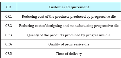
Verify the customer requirement .Obtain customer opinion by surveys, opinion polls and interviews. Table 3 shows the essential customer requirement.
Table 3: The essential customer requirement for progressive die designing.
Phase2: Design
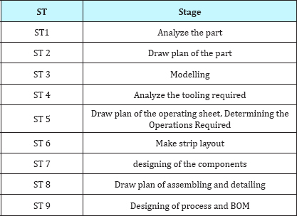
Step 1: Verify and identify stages of progressive die designing
The stages of progressive die designing are obtained from 3 ways:
Verify the document of progressive die designing and observe the method of progressive die designing practically in a workshop. Study the articles and handbook and sites about progressive die designing Interview with experts face-to-face. Table 4 shows the result of these 3 ways
Table 4: The result of these 3 ways.
Step 2: Identify and assign CTQ
A die designer properly investigates the functional requirements of the component. The critical study is carried out to identify the required mechanical properties an possible causes which may result the failure of the component. These are the basic causes which may result the failure of the progressive die: Inaccuracy in die design not using proper tools in production process Material is not good quality & Inaccuracy die manufacturing Inaccuracy in assembling.
Phase 3: Optimize
In this stage, we must optimize. So it is necessary Find out the essential stages. The objective is to select the key stages. We calculated by QFD.
QFD
For filling the matrix of HOQ, we need the customer importance. Develop a hierarchical structure with the customer requirement s. The relations shown in Figure 3.
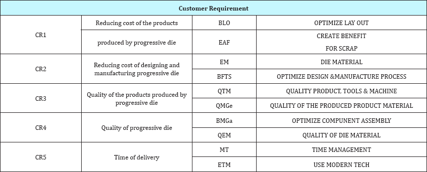
To prepare the ANP method, we define the sub requirement.Table 5 shows these.
Figure 3: The relations of CR.
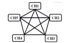
Table 5: Sub requirement.
(Figure 4 & Table 6)
Figure 4: Diagram for ANP.
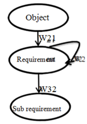
Table 6: The relation of sub CR.
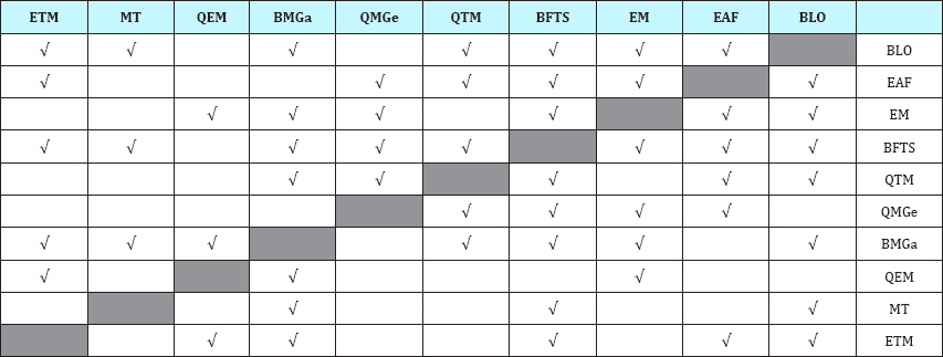
Find out the relative importance of different factors with respect to the goal or objective;
a) Construct a pair-wise comparison matrix using a scale of relative importance. The judgments are entered using the fundamental scale of the AHP Saaty [26,45] as given in Table 7.
Table 7: Comparison matrix.

Relative importance of factors
Assuming N factors; the pair-wise comparison of factor i with factor j yields a square matrix A1N*N where aij denotes the relative importance of factor I with respect to factor j. In the matrix, aij= 1 when i= j and aji= 1/aij
b) Find the relative normalized weight (Wi) of each factor by calculating the geometric mean of with row and normalizing the geometric means of rows in the comparison matrix.
The customer importance (C I ) is shown in Table 8.
Table 8: Customer importance.

Now, fill the HOQ matrix by the fundamental scale as given in Table 9,10.
Table 9: Relative importance of factors.

Table 10: House of quality.
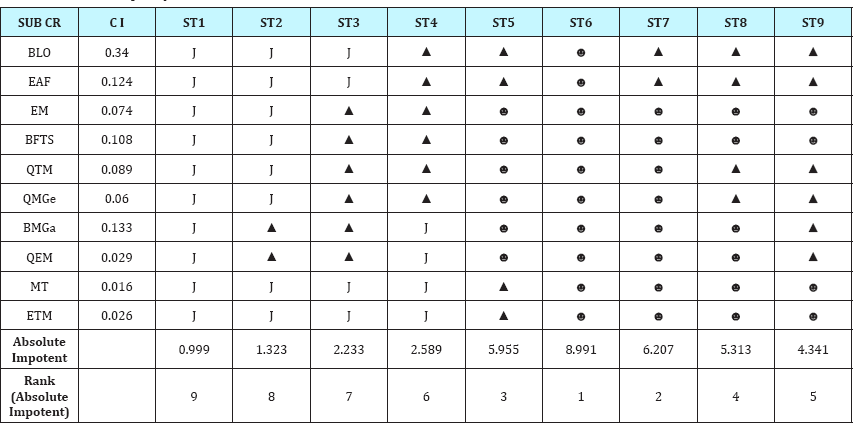
Phase 4: validating
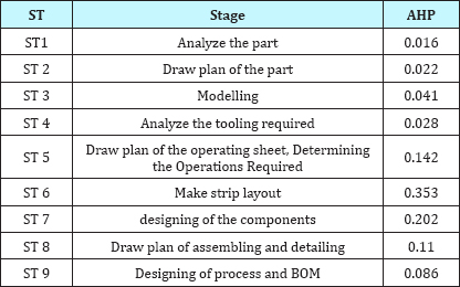
In this phase for validating the priority of stages calculates by AHP method.
The result is shown in Table 11.
Table 11: AHP Result.
Conclusion
To compare the result of QFD and AHP (Table 10,11), the important stages are:
Make strip layout designing of the components
Draw plan of the operating sheet, determining the Operations Required. By focusing in these stages, we can design an accurate progressive die. Strip-layout design is to arrange layout of the operations and subsequently determine the number of stations required. Strip layout is mainly governed by the geometrical features of the part, tolerance on dimensions of the part, direction of sharp edge of stock strip and other technical requirements.
Design of progressive die is a complex and highly specialized procedure and typically progressive die design takes 20% of the lead time from the concept design to the final stamping manufacture. The choice of an efficient strip layout is an important step during die design, because as only the optimum layout can reduce wastage of the strip material and reduce the overall cost of production.
References
- Taylan A (1998) Metal forming handbook, schuler. Berlin Heidelberg, New York, USA.
- Gashaw D, Yonas MD (2014) Progressive Die Design for Self Explosive Reactive Armor Holder. International Journal of Engineering and Science (IJES) 3(3): 75-85.
- Ivana S (1998) Hand Book of Die Design, (2nd edn), McGraw-Hill 2006, 1998.
- Kovach J, Turner J, Rae CB (2005) The House of Competitiveness: The marriage of agile manufacturing, design for six sigma, and lean manufacturing with quality considerations. Journal of Industrial Technology 21(3).
- Hauser, Clausing (1988) The House Of Quality Hober. In: Charles, Mazur (Eds,). QFD and Design for Six Sigma. 14th Symposium on QFD.
- Kumar S, Singh R (2011) An automated design system for progressive die. Expert Systems with Applications 38(4): 4482-4489.
- Murikama S, Shirai K, Murkami H (1989) A compact and practical CAD/CAM system for progressive dies. Bulletin of the Japan Society of Precision Engineering 23: 25-30.
- Sima SB, Lee ST, Jang CH (2004) A study on the development of center carrier type progressive die for U-bending part process. Journal of Materials Processing Technology 153-154: 1005-1010.
- Ghatrehnaby M, Arezoo B (2009) A fully automated nesting and piloting system for progressive dies. Journal of Materials Processing Technology 209(1): 525-535.
- Duffy MR, Sun Q (1991) Knowledge-based design of progressive stamping dies. Journal of Materials Processing Technology 28(1-2): 221227.
- Lee IBH, Lim BS, Nee YC (1993) Knowledge-based process planning system for the manufacture of progressive dies. International Journal of Production Research 31(2): 251-278.
- Cheok BT, Foong KY, Nee AYC (1996) An intelligent planning aid for the design of progressive dies. Proceeding of Institution of Mechanical Engineers- Part B: Journal of Engineering Manufacture 210(1): 25-35.
- Ismail HS, Chen HK, Hon KK (1996) Automated design of progressive dies. Proceeding of Institution of Mechanical Engineers Part B: Journal of Engineering Manufacture 210(4): 367-376.
- Zheng J, Wang Y, Li Z (2007) KBE- based stamping process paths generated for automobile panels. International Journal of Advanced Manufacturing Technology 31(7-8): 663- 672.
- Caiyuan L, Jianjun W, Jianyong X, Xiangzhi (2001) HPRODIE: using feature modeling and feature mapping to speed up progressive die design. Int J Prod Res 39(18): 4133-4151.
- Kumar S, Singh R (2007) A short note on an intelligent system for selection of materials for progressive die components. Journal of Materials Processing Technology 182(1-3): 456-461.
- Brue G, Launsby RG (2003) Design for six sigma. McGraw-Hill, New York, USA.
- Hahn G, Doganaksoy N, Hoerl R (2007) The evolution of six sigma. Quality Engineering 12(3): 317-326.
- Tennant G (2002) Design for six sigma: launching new products and services without failure. Gower Publishing Limited: Hampshire, UK.
- Soderborg N (2004) Design for Six Sigma at Ford. Six Sigma Forum Magazine 4(1): 15-22.
- Creveling CM, Slutsky JL, Antis D (2003) Design for Six Sigma-In Technology and Product Development. Prentice-Hall PTR: NJ, 2003.
- Yang K, El-Haik B (2003) Design for six sigma-a roadmap for product development. McGraw- Hill, New York, USA.
- Charles H, Mazur Glen "QFD and Design for Six Sigma” 14th Symposium on QFD.
- Yihai He, Xiaoqing T, Wenbing C (2009) Technical decomposition approach of critical to quality characteristics for product design for six sigma. Quality and Reliability Engineering International 26(4): 325-339.
- Cohen L (1995) Quality Function Deployment: How to Make QFD Work for You. Addison- Wesley, Reading, MA.
- Saaty TL (1980) The analytic hierarchy process. McGraw- Hill, New York, USA.
- William H (2008) Integrated analytic hierarchy process and its applications- A literature review. European Journal of Operational Research 186(1): 211-228.
- Saaty TL (1996) Decision making with dependence and feedback: analytic network process. RWS Publications, Pittsburgh, USA.
- Saaty TL (1999) Fundamentals of the analytic network process. International Symposium on the Analytic Hierarchy Process, Kobe, Japan, pp. 1-14.
- Meade LM, Presley A (2002) R&D project selection using the analytic network process. IEEE transactions on engineering management 49(1): 59-66.
- Lee JW, Kim SH (2000) Using analytic network process and goal programming for interdependent information system project selection. Computers & Operations Research 27(4): 367-382.
- Karsak EE, Sozer S, Alptekin SE (2002) Product planning in quality function deployment using a combined analytic network process and goal programming approach. Computers & industrial engineering 44(1): 171-190.
- Sarkis J (2003) A strategic decision framework for green supply chain management. Journal of Cleaner Production 11(4): 397-409.
- Momoh JA, Zhu J (2003) Optimal generation scheduling based on AHP/ ANP. IEEE Trans. Systems Man Cybernet- Part B: Cybernet 33(3): 531535.
- Fontela E, Gabus A (1974) DEMATEL, innovative methods, Report no.2, Structural analysis of the world problem atique. Battelle Geneva Research Institute, Switzerland.
- Fontela E, Gabus A (1976) The DEMATEL observer. Battelle Institute, Geneva Research Center 7(9).
- Warfield JN (1976) Societal systems, planning, policy and complexity. John Wiley & Sons, New York, USA.
- Chiu YJ, Chen HC, Tzeng GH, Shyu JZ (2006) Marketing strategy based on customer behaviour for the LCD-TV. International Journal of Management and Decision Making 7(2-3): 143-165.
- Hori S, Shimizu Y (1999) Designing methods of human interface for supervisory control systems. Control Engineering Practice 7(11): 14131419.
- Liou JJH, Tzeng GH, Chang HC (2007) Airline safety measurement using a hybrid model. Air Transport Management 13(4): 243-249.
- Wu WW, Lee YT (2007) Developing global managers' competencies using the fuzzy DEMATEL method. Expert Systems with Applications 32(2): 499-507.
- Lin CJ, Wu WW (2008) A causal analytical method for group decisionmaking under fuzzy environment. Expert Systems with Applications 34(1): 205-213.
- Tzeng GH, Chiang CH, Li CW (2007) Evaluating intertwined effects in e-learning programs: a novel hybrid MCDM model based on factor analysis and DEMATEL. Expert Systems with Applications 32 (4): 10281044.
- Huang CY, Tzeng GH, Joseph ZS (2007) Reconfiguring the innovation policy portfolios for Taiwan's SIP Mall industry. Technovation 27(12): 744-765.
- Saaty TL (2000) Fundamentals of decision making with the analytic hierarchy process. RWS Publications, Pittsburgh, USA.
© 2018 Amir Abbas Shojaie. This is an open access article distributed under the terms of the Creative Commons Attribution License , which permits unrestricted use, distribution, and build upon your work non-commercially.
 a Creative Commons Attribution 4.0 International License. Based on a work at www.crimsonpublishers.com.
Best viewed in


.jpg)


 Editorial Board Registrations
 Submit your Article
 Refer a Friend
 Advertise With Us
.jpg)


.jpg)


.bmp)
.jpg)
.png)
.jpg)


.jpg)


.png)

.png)


.png)


