- Submissions

Full Text
Advancements in Civil Engineering & Technology
Internal Pressure Capacity and Corrosion Behavior of Composite System Joining Metallic Pipes
Hossam M1, Mahdi E1*, Dean A2 and Cabibihan JJ1
1Department of Mechanical and Industrial Engineering, College of Engineering, Qatar University, Qatar
2School of Civil Engineering, College of Engineering, Sudan University of Science and Technology, Sudan
*Corresponding author:Mahdi E, Department of Mechanical and Industrial Engineering, College of Engineering, Qatar University, P. O. Box 2713, Doha, Qatar
Submission: December 20, 2022;Published: January 06, 2023

ISSN: 2639-0574 Volume5 Issue3
Abstract
This paper examines the effect of fiber-reinforced plastic (FRP) types on the internal pressure capacity and corrosion behavior of joined metallic pipes. To this end, fabrication processes of aluminum pipes have been prepared to be used later for wrapping with different FRP and welding. The FRP used are kevlar fiber/epoxy (KFRP) and carbon fiber/epoxy (CFRP). These fibers have been cut into strips and utilized in the joining systems using the fabric-winding method. Two types of pipes have been considered: pipes joined with four layers of KFRP and pipes with eight layers of KFRP-CFRP. On the other hand, pipes with two types of welding have been used for comparison purposes. The results showed improvement in the pipe’s internal pressure capacity compared to welding. Finally, the corrosion test was carried out. The results showed that FRP joining systems have higher corrosion resistance than welded and non-joined pipes. These results revealed that using FRP composites in pipe joining shows a promising future.
Keywords:Composites; Metalic pipes; Joining; Internal pressure capacity; Corrosion
Introduction
Transportation pipeline
Pipelines have been used for a long time to supply towns and cities with drinking water [1]. For the oil and gas industry, the first use of pipelines was in mid of the 1800s in the United States [2]. The main objective of pipelines is to carry the oil and gas from its sources like crude oil or gaseous to the processing facilities and distribution units. High demands on energy worldwide require a fast and effective way of transporting huge amounts of oil or gas. Accordingly, the most effective and practical way of oil and gas transportation has been used for a long time is pipelines. Depending on needs, pipelines can vary from a few kilometers to thousands of kilometers to deliver oil or gas to different destinations or even other countries. Accordingly, Pluvinage and Elwany [3] stated that the total length of gas transportation pipelines worldwide is around 1 million km; 450,000km is in the USA, while 235,000km is in Russia [3].
Meanwhile, Mahmoodian and Li [2] stated that the United States has 800,000km of pipelines for transporting products like natural gas, crude oil, and petroleum [2]. Pipelines can be classified based on materials such as conventional pipelines (i.e., mostly metallic) and composite pipelines. More details about these two types are given in the below sections.
Conventional pipelines
Conventional oil and gas transportation pipelines are mostly made from different steel types [4]. It is well known that carbon steel pipes, as well as high-strength low alloy steel pipes, have been widely used for oil and gas transportation due to their high-strength properties [5,6]. High-pressure capacity and high strength properties of pipelines are essential factors for oil and gas transportation in different environmental conditions like offshore or onshore, buried or above the ground [4,7,8]. It is also worth mentioning that designing pipelines is based on well-known standards and codes such as ASME and API.
Composite pipelines
Fiber-reinforced polymer composite (FRP) pipelines became an alternative to metallic pipelines because of their excellent performance and cost-effectiveness [9,10]. FRP composite pipes were first developed after the 2nd world war. They consist of woven or chopped fibers and resin applied over a mandrel and molded using the hand lay-up technique. Manufacturing of the first commercial composite pipes started in the mid-1950s. With time, the manufacturers developed a filament-winding process to produce high-performance composite pipes.
Challenges in pipelines design
Piping techniques have many challenges to meeting the requirements for design and operation, which are usually specified in codes and standards primarily in the oil and gas industry. For example, it is well known that maintenance of pipelines due to leakage or rupture is a significant challenge for pipeline engineers [7],11-14]. Maintenance of pipelines is a costly activity, which can be increased in the case of offshore pipelines or buried pipelines. On the other hand, extended networks of pipelines need joining techniques to connect thousands of kilometers of pipelines. Therefore, pipeline joining is considered a significant challenge in pipeline design. It is also evident that the type and location of joints controlled the pipeline’s failure [15]. This is because designers consider joints critical locations (i.e., stress risers).
Moreover, in the case of elbow and T-joints, the stress concentration is attributed to the abrupt change in the geometry of the pipeline, which leads to catastrophic failures in pipelines [16,17]. In addition to the joining challenge, the effect of corrosion on the pressure capacity of the pipeline is very significant, and it deteriorates the pipeline integrity and shortens its lifetime. Furthermore, if not adequately considered in the design, combining these factors will lead to an unplanned shutdown [18,19]. As mentioned earlier, two significant challenges arise in pipelines: corrosion and joining; these two considerable challenges are discussed in the below sections.
Effect of welding on pipes pressure behavior
Stress concentrations appear due to circumferential butt welds, buckling arrestors, and welds at flanges connectors in pipelines. Those stress concentrations affect the lifetime of pipelines due to cyclic internal pressure due to the starting and shutdown of operations or gas transportation where the pressure changes inside the pipelines [17]. In addition, residual stresses induced by the welding process significantly affect the plastic behavior of pressurized pipes with girth-welds subjected to cyclic bending because of enhancing the hoop strain rate compared to pressurized pipes with no girt-welds. It has been found that hoop strain increases as the bending load or the internal pressure increase [16]. Lee and Chang [16] have studied the residual stresses in girthwelded steel pipes and their evolution under internal pressure. Their results showed that the internal pressure applied to girthwelded pipes with open ends showed compressive hoop stress in the girth-weld due to circumferential shrinkage results from the welding process. This leads to a second axial bending moment, where tensile axial stresses are presented at the outside surface of the pipe and compressive stresses on the inside surface of the pipe in and around the weld. While for the internal pressure applied to girth-welded pipes with closed ends, an extra bending moment at the girth-weld attributed to the reduced diameter during the welding process is produced in addition to the secondary bending moment [20].
In this study, the internal pressure capacity and corrosion behavior of composite system joining metallic pipes have been studied and compared to welded and non-joined pipes. The paper is organized as follows. Section 2 outlines the methodology being applied to carry out the experimental investigation. Section 3 presents and discusses the results obtained from experimental tests in detail. Finally, the main contributions of this investigation are resumed in Section 4.
Experimental Programs
Herein, the sequences of sample preparation and the procedure followed in conducting the experiments are described.
Materials
Aluminum pipes:Aluminum pipes of 50mm outer diameter and 3mm thickness have been used in this research to carry out bending tests for welded pipes and composite joining pipes, as well as internal pressure tests and corrosion investigation, see Figure 1.
Figure 1:An aluminum pipe with (a 50 mm) outer diameter and (3 mm) thickness.

Composites
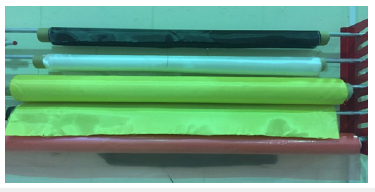
Two different types of fibers have been used: kevlar and carbon fiber. These fibers are in woven sheets form with 0˚-90˚ see Figure 2.
Figure 2:Woven sheets of fibers: kevlar fibers (yellow color) and carbon fibers (black color).
Sample preparation
Aluminum pipes for welding:Aluminum pipes of 1 m total length have been cut in the middle and subjected to commercial welding using aluminum filler wire. The welding process involved two different methods: V-welding and faced butt welding. The V-welding pipes were prepared by removing material from the edge of the pipe on a slope. This method has allowed the filler material to be intensively distributed through the joint and to provide higher welding quality. For the faced butt-welding method, the pipes were faced together after cutting, and welding was applied directly to join the two pipes.
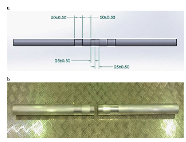
Aluminum pipes for composite joining:Aluminum pipes of 1m total length have been cut in the middle, and the groove of 1.5 mm depth and 5 cm width has been applied, as shown in Figure 3, to allow for the wrapping process. A small solid cylindrical piece of aluminum has been used to mount the two parts of the pipes together for the wrapping process.
Figure 3:Aluminum pipe prepared for fabrication: (a) dimensions produced by Solidworks, and (b) sample after preparation.
Fibers preparation:All fibers (kevlar and carbon fiber) are in woven sheets, with 0˚-90˚ angles orientation. The woven sheets have been cut into long strips 5 cm in width. These strips have been cut with the same angle of 0˚-90˚. Cutting with different angles has also been performed, but during the fabrication process, the trial for wrapping fibers with different angles failed due to fiber condensing and crushing; hence only a normal cut with 0˚-90˚ was successfully to be used in fabrication. These strips have been used in wrapping 0˚-90˚ as well as 45˚-45˚ by adjusting the angle of wrapping to 45˚. Other angles have been difficult to wrap since they need manual adjusting for the angle when using 0˚-90˚ strips.
Fabrication process:Pipes have been coupled by placing a solid cylindrical piece of aluminum inside the two parts of the pipes to prepare them for fabrication. This piece of aluminum has been covered with a layer of nylon to ease its removal after the fibers are cured. The fabrication has been done by wrapping the joined pipes with fiber strips from groove to groove.
Internal pressure test procedure
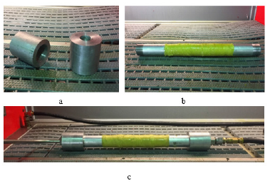
The test has been carried out using Resato high-pressure machine model SPU-CC-2000. The reset machine applies pressure using corroded oil fluid pressurized by a high-pressure air pump with a maximum capacity of 2000 bar. The test starts with filling the pipe and then performing low pressure to ensure there is no leak before conducting the pressure test with 1MPa/min. After fabrication, the pipes delegated for the internal pressure test have been threaded from each side to fit in prepared fixtures for this test, see Figure 4. These two fixtures have been fabricated to allow the inlet and outlet hoses of the machine to be fixed to the pipes.
Figure 4:(a) fixtures, (b) a pipe with threads, and (c) pipe after fixation with inlet and outlet hoses.
Corrosion investigation procedure
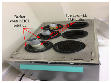
Corrosion investigation has been carried out on the two types of FRP composites joining (KFRP and CFRP) and the welded and non-joined pipes. First, the specimens were sealed from one side using chemical-resistant sealing. They were then immersed in 1.5M of HCl solution as corrosive media. The use of HCL is to imitate the severe environmental condition in the Gulf region, see Figure 5. In addition, to accelerate the corrosion process, a heater containing water at a temperature of 50 ˚C has been used as a surrounding media to the solution, see Figure 6.
Figure 5:Aluminum pipe specimens before corrosion experiment: (a) welded aluminum pipe (b) non-welded aluminum pipe (c) aluminum pipe joined with KFRP(d) aluminum pipe joined with CFRP.
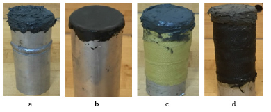
Figure 6:Beakers contain solution and specimens immersed in the heater.
Results and Discussion
Herein, the results of internal pressure capacity for KF – four layers and (CF-KF) – eight layers, which have been selected by optimization for bending test results [21], are presented and discussed in detail.
Figure 7:Aluminum pipes with KF joining under combined axial and radial internal pressure test.
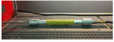
Figure 8:kevlar joining under combined axial and radial internal pressure.
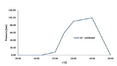
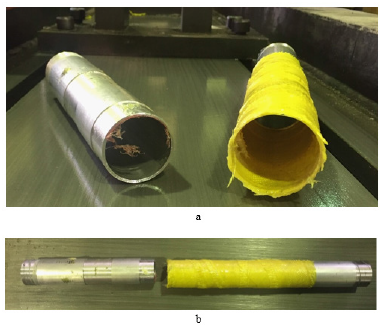
Figure 9:Split of the joint from the pipe.
Radial internal pressure
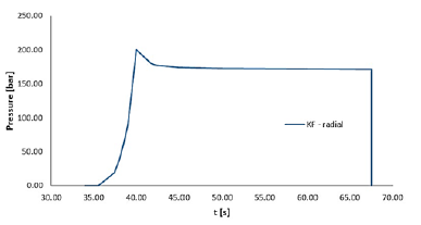
For the radial internal pressure test, a new fixation has been used as a case to hold both sides of the pipe. This fixation has been designed as two plates connected using four long threaded rods with nuts for tiding. These two plates have a cup groove where the original two pipe fixtures can be placed, see Figure 10. The result of the KF under radial internal pressure test showed a significant increase in the internal pressure capacity of the pipe. The failure was observed at 200 bar after 30s from filling completion, see Figure 11. The failure occurred as leakage from the kevlar joint edges without any breakage or visual deformation in the pipe or the joint. Again, this failure is related to resin cracks in the layer, which is in contact with the pipe’s surface. After removing the pipe from the test fixtures, it was noticed that the joint was still connected to the pipe and could not be removed by hand.
Figure 10:Fixation for radial internal pressure test.
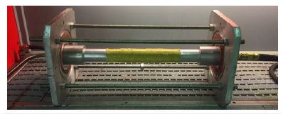
Figure 11:Kevlar joining under radial internal pressure.
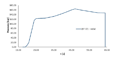
The effect of (CF-KF)-8 layers fiber-reinforced composite:As shown in Figure 12, the result of (CF-KF)-8 layers joined aluminum pipes under radial internal pressure test failed 160 bar after 40s from filling completion. The failure occurred as leakage from the composite joint edges, without any breakage or visual deformation in the pipe or the joint, as observed in KF-4 layers. Again, this failure is related to resin cracks in the layer, which is in contact with the pipe’s surface. After removing the pipe from the test fixtures, it was noticed that the joint was still connected to the pipe and could not be removed by hand. This result was lower than the results obtained from the KF-4 layers test, although it took a long time to occur. This finding can be referred to as hand lay-up problems during the fabrication process, including the amount of resin used. It indicates that the fabrication process quality could affect the results significantly.
Figure 12:(KF-CF) joining under radial internal pressure.
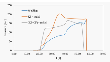
The effect of fiber-reinforced composite: The results for welded aluminum pipe under radial internal pressure test showed failure at 165 bar, see Figure 13. The KF-4 layers showed a higher internal pressure capacity of 200 bar. Although (CF-KF)-8 layers showed similar internal pressure capacity to welded aluminum pipe, it is believed that this behavior can be improved by higher quality in the fabrication process. In general, using composites for joining pipes shows a promising method for higher performance in terms of internal pressure compared to welding methods.
Figure 13:Internal pressure capacity of composite joining vs. welding.
Summary of internal pressure test outcomes: Using fiber composites in joining has significantly improved the internal pressure capacity of joined pipes compared to classic welding techniques. The failure in fiber composite joined pipes is anticipated in the edge of the joint as leakage due to resin cracking in the attached layer to the pipe’s surface and before any visual deformation in the pipe’s bulk or the joint bulk. In addition, the quality of the fabrication
Corrosion behavior
Figure 14:Aluminum pipe joined with FRP composites after one week of corrosion experiment: (a) aluminum pipe joined with KFRP, and (b) aluminum pipe joined with CFRP.
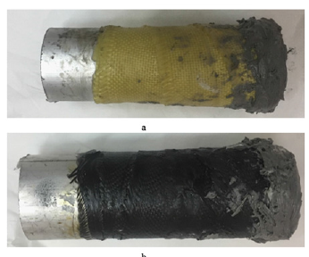
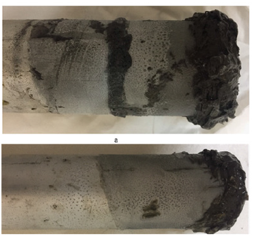
The corrosion experiment has been designed to investigate the corrosion resistance of different FRP composite types compared to weld and base metal. The figures for different specimens before and after immersing them in 1.5M HCl solution are presented. The experiment showed that corrosion was formed in welded and non-joined pipes. Figure 14 shows the aluminum pipe joined with FRP composites after one week of corrosion experiment where no corrosion was observed at the joining area. However, pitting corrosion started in both welded and non-welded aluminum pipes after one week of conducting the corrosion experiment, see Figure 15, due to acid attacking the oxide film on aluminum pipes.
Figure 15:Corrosion in (a) welded and (b) non-welded aluminum pipe.
Concluding Remarks and Outlook
In this study, using fiber composite in pipe joining has been investigated in terms of internal pressure capacity and compared to the welding method, which has many limitations in terms of lack of properties. Kevlar and carbon fiber have been used as joining composites for aluminum pipes.
Internal pressure test has been carried out on the optimized types of joining resulting from the bending test, which was KF-4 layers and (CF-KF)-8 layers. The results showed that using fiber composites in joining has significantly improved the internal pressure capacity of joined pipes compared to classic welding. However, the failure in the case of fiber composites joining under internal pressure test has been observed as leakage from the joint edges without any visual deformation in the joint structure or pipe bulk.
Finally, a corrosion test was carried out. The results showed that FRP joining systems have higher corrosion resistance than welded and non–joined pipes. These results revealed that using FRP composites in pipe joining shows a promising future for pipe joining to achieve free corrosion pipelines. In the next step, the sophisticated models developed [22-27] will be employed to numerically investigate the failure behavior further of the proposed joining system under different loading conditions. Further research activities in this area would regard the investigation of the joining system under fatigue loadings, see [28-31], crushing forces, see [32-34], as well as the durability of the joining system.
Acknowledgment
The work is supported by a research grant from Qatar University under the Grant No. NPRP 11S-1229-170145. The statements made herein are solely the responsibility of the authors.
References
- Kennedy JL (1993) Oil and gas pipeline fundamentals, (2nd edn). Okla: Pennwell Corp, Tulsa, USA.
- Mahmoodian M, Li CQ (2016) Stochastic failure analysis of defected oil and gas pipelines. Handbook of Materials Failure Analysis with Case Studies from the Oil and Gas Industry, pp. 235-255.
- Pluvinage G, Elwany MH (2008) Safety, reliability and risks associated with water, oil and gas pipelines. Dordrecht: Springer Netherlands.
- Sharma SK, Maheshwari S (2017) A review on welding of high strength oil and gas pipeline steels. J Nat Gas Sci Eng 38: 203-217.
- Mathias LLS, Sarzosa DFB, Ruggieri C (2013) Effects of specimen geometry and loading mode on crack growth resistance curves of a high-strength pipeline girth weld. Int J Press Vessels Pip 111-112: 106-119.
- Zhu J, Xu L, Chang W, Hu L, Lu M (2014) Microstructures and mechanical properties of welded joints of novel 3Cr pipeline steel using an in-house and two commercial welding wires. Mater Des 53: 405-411.
- Eliyan FF, Mahdi ES, Alfantazi A (2012) Electrochemical evaluation of the corrosion behavior of API-X100 pipeline steel in aerated bicarbonate solutions. Corros Sci 58: 181-191.
- Eliyan FF, Mahdi ES, Alfantazi A (2013) Investigating the corrosion of API-X100 pipeline steel in aerated carbonate solutions by electrochemical methods. Int J Electrochem Sci 8: 578-590.
- Mahdi E, Eltai E (2018) Development of cost-effective composite repair system for oil/gas pipelines. Compos Struct 202: 802-806.
- Mahdi E, Hamouda AMS, Sahari BB, Khalid YA (2003) Experimental quasi-static axial crushing of cone-tube-cone composite system. Compos Part B Eng 34(3): 285-302.
- Mandel M, Krüger L (2015) Long-term corrosion studies of a CFRP/EN AW-6060-T6 Self-piercing rivet Joint and a Steel/EN AW-6060-T6 Blind Rivet Joint. Mater Today Proc 2 (Supp 1): S131-S140.
- Aminul Islam Md, Farhat ZN, Ahmed EM, Alfantazi AM (2013) Erosion enhanced corrosion and corrosion enhanced erosion of API X-70 pipeline steel. Wear 302(1-2): 1592-1601.
- Popoola LT, Grema AS, Latinwo GK, Gutti B, Balogun AS (2013) Corrosion problems during oil and gas production and its mitigation. Int J Ind Chem 4(1): 35.
- Mahdi E, Rauf A, Ghani S, El-Noamany A, Pakari A (2013) Erosion-corrosion behavior and failure analysis of offshore steel tubular joint. Int J Electrochem Sci 8: 7187-7210.
- Kumar P, Singh RK, Kumar R (2007) Joining similar and dissimilar materials with GFRP. Int J Adhes Adhes 27(1): 68-76.
- Bae WG, Chang KH, Lee CH (2016) Progressive inelastic deformation of a girth-welded stainless-steel pipe under internal pressure and cyclic bending. Ocean Eng 128: 81-93.
- Lotsberg I (2008) Stress concentration factors at welds in pipelines and tanks subjected to internal pressure and axial force. Mar Struct 21(2-3): 138-159.
- Vanaei HR, Eslami A, Egbewande A (2017) A review on pipeline corrosion, in-line inspection (ILI), and corrosion growth rate models. Int J Press Vessels Pip 149: 43-54.
- Xu S, Wang H, Li A, Wang Y, Su L (2016) Effects of corrosion on surface characterization and mechanical properties of butt-welded joints. J Constr Steel Res 126: 50-62.
- Lee CH, Chang KH (2013) Study on the residual stresses in girth-welded steel pipes and their evolution under internal pressure. Mar Struct 34: 117-134.
- Sebaey TA, Mahdi E (2016) Crashworthiness of pre-impacted glass/epoxy composite tubes. Int J Impact Eng 92: 18-25.
- Dean A (2017) Material modeling of short fiber reinforced polymeric composites: Theory, numerical aspects, and applications. ISD, Institute for Statics and Dynamics.
- Dean A, Grbic N, Rolfes R, Behrens B (2019) Macro-mechanical modeling and experimental validation of anisotropic, pressure- and temperature-dependent behavior of short fiber composites. Compos Struct 211: 630-643.
- Dean A, Sahraee S, Reinoso J, Rolfes R (2017) A new invariant-based thermo-plastic model for finite deformation analysis of short fiber reinforced composites: Development and numerical aspects. Compos Part B Eng 125: 241-258.
- Dean A, Sahraee S, Özenc K, Reinoso J, Rolfes R, et al. (2017) A thermodynamically consistent framework to couple damage and plasticity micro plane-based formulations for fracture modeling: Development and algorithmic treatment. Int J Fract 203(1): 115-134.
- Dean A, Reinoso J, Jha NK, Mahdi E, Rolfes R (2020) A phase field approach for ductile fracture of short fiber reinforced composites. Theor Appl Fract Mech 106: 102495.
- Dean A, Asur Vijay kumar PK, Reinoso J, Gerendt C, Paggi M, et al. (2020) A multi-phase-field fracture model for long fiber reinforced composites based on the puck theory of failure. Compos Struct 251: 112446.
- Brod M, Just G, Dean A, Jansen E, Koch I, et al. (2019) Numerical modeling and simulation of fatigue damage in carbon fiber reinforced plastics at different stress ratios. Thin-Walled Struct 139: 219-231.
- Brod M, Dean A, Scheffler S, Gerendt C, Rolfes R (2020) Numerical modeling and experimental validation of fatigue damage in Cross-Ply CFRP composites under inhomogeneous stress states. Compos Part B Eng 200: 108050.
- Brod M, Dean A, Rolfes R (2021) Numerical life prediction of unidirectional fiber composites under block loading conditions using a progressive fatigue damage model. Int J Fatigue 147: 106159.
- Gerendt C, Dean A, Mahrholz T, Englisch N, Krause S, et al. (2020) On the progressive fatigue failure of mechanical composite joints: Numerical simulation and experimental validation. Compos Struct 248: 112488.
- Alkhatib F, Mahdi E, Dean A (2020) Crushing response of CFRP and KFRP composite corrugated tubes to quasi-static slipping axial loading: experimental investigation and numerical simulation. Compos Struct 246: 112370.
- Alkhatib F, Mahdi E, Dean A (2020) Development of composite double-hat energy absorber device subjected to traverser loads. Compos Struct 240: 112046.
- Alkhatib F, Mahdi E, Dean A (2021) Design and evaluation of hybrid composite plates for ballistic protection: experimental and numerical investigations. Polymers 13(9): 1450.
© 2023 Mahdi E. This is an open access article distributed under the terms of the Creative Commons Attribution License , which permits unrestricted use, distribution, and build upon your work non-commercially.
 a Creative Commons Attribution 4.0 International License. Based on a work at www.crimsonpublishers.com.
Best viewed in


.jpg)


 Editorial Board Registrations
 Submit your Article
 Refer a Friend
 Advertise With Us
.jpg)


.jpg)


.bmp)
.jpg)
.png)
.jpg)


.jpg)


.png)

.png)


.png)


