- Submissions

Full Text
Advancements in Civil Engineering & Technology
Analytical Analysis: Hybrid Triple Skin Stainless Steel Tubular Columns Filled with Uhpfrcand Externally Gfrp-Jacketed Under Lateral Impact Load
Khalid Abdel Naser Abdel Rahim*
Department of Civil Engineering, Faculty of Science and Technology, University of Coimbra, Portugal
*Corresponding author: Khalid Abdel Naser Abdel Rahim, Department of Civil Engineering, Faculty of Science and Technology, University of Coimbra, Portugal
Submission: January 05, 2021;Published: January 20, 2022

ISSN: 2639-0574 Volume4 Issue5
Opinion
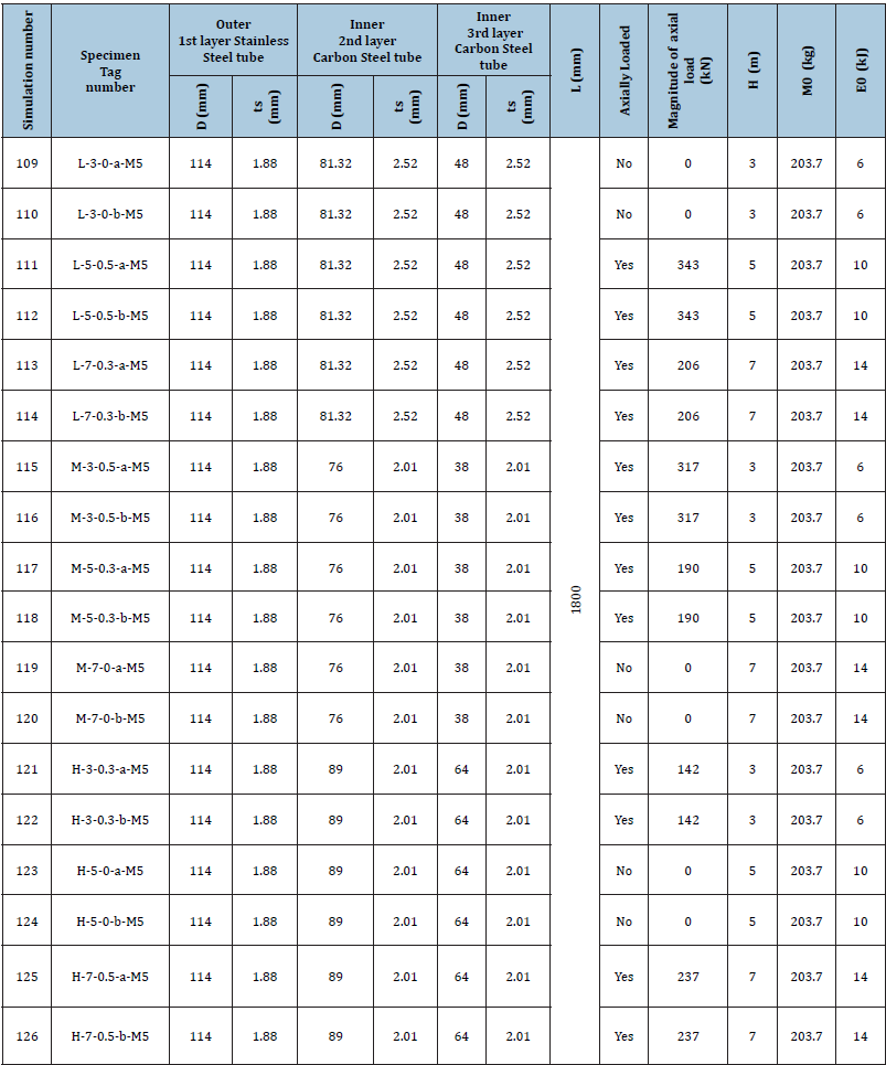
Abdel Rahim [1] proposed many modifications on the CFDST specimens which were carried out by Zhao et al. [2]. Continuosly, this opinion manuscript proposes further design modifications. By extending double skin CFST to hybrid triple skin CFST with an extra Glass Fiber Reinforced Polymer (GFRP) reinforcement layer installed on the outer stainlesssteel tube. In addition, this design modification which is anticipated by the author of this opinion paper has three concrete fill sandwich layers. The first concrete fill sandwich layer lays between the outer stainless steel tube and the inner second layer carbon steel tube. Besides, the first concrete fill sandwich layer will be filled with Ultra High-Performance Fiber Reinforced Polymer (UHPFRC). Furthermore, the second concrete fill sandwich layer lays between the inner second layer carbon steel tube and the inner third layer carbon steel tube. Moreover, the second concrete fill sandwich layer will be filled with Normal Strength Concrete (NSC). Moreover, the third concrete fill sandwich layer will be located in the core of the inner third skin carbon steel tube. In addition, the third concrete fill sandwich layer will be filled with Normal Strength Concrete (NSC). Besides, the outer stainless-steel tube will wrapped with one layer of GFRP with an elastic modulus of 23GPa, a tensile strength of 508MPa and a thickness of 0.49mm with reference to the material properties indicated by Alam et al. [3]. Also, the numerical modeling and analysis for this proposed design will take into consideration an adhesive with elastic modulus of 3GPa and a tensile strength of 46MPa as recommended by Alam et al. [3]. This adhesive will be used in gluing the GFRP reinforcement layer to the outer stainless steel tube. Even though, Alam et al. [3] did not mention the thickness of the adhesive, the author of this paper has assumed it to be one third of the thickness of the GFRP layer (assumed adhesive thickness approximately 0.16mm). Afterwards, the structural behavior will be assisted under transverse impact loading. Moreover, the results obtained will be compared with the experimental results achieved by Zhao et al. [2] to determine the percentage of increase in the impact resistivity of this design scheme. The design scheme of this study consists of eighteen numerical models (simulation numbers 109 to 126). Moreover, three main variables will be evaluated. These are (1) diameter of internal carbon steel tube, (2) magnitude of axial load and (3) drop height. Besides, the list which presented in Table 1 includes details of the simulation numbers, specimens tag numbers, type of modification for this stage, diameter and thickness of the steel tubes, length of the specimens, magnitude of axial load, drop heights, impact mass, impact energy and geometry and size of indenter.
Table 1: List ofgeometrical properties, cross sectional dimensions and impact loading conditions for hybrid triple skin stainless steel tubular columns filled with UHPFRC and externally GFRP-Jacketed under lateral impact load.

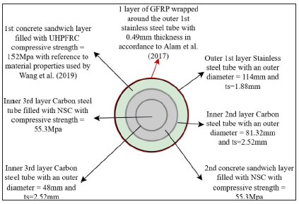
A schematic drawing has been shown in Figure 1 of the CFTST cross section with the new modification and material properties for specimens with an addition 2nd internal tube (D=81.32mm). As can be seen in Figure 1, the model consists of three steel tubes. The first layer outer steel tube is made from stainless steel with an outer diameter of 114mm with a tube thickness of 1.88mm. On the other hand, the second layer inner steel tube represents the additional proposed steel skin and is made from carbon steel with an outer diameter of 81.32mm and a thickness of 2.52mm. Moreover, the third layer inner steel tube is made from carbon steel with an outer diameter of 48mm and tube thickness of 2.52mm. Also, the material properties of stainless steel and carbon steel should be in accordance to Zhao et al. [2]. Furthermore, the first concrete fill sandwich layer between the outer stainless steel tube and the inner second layer carbon steel tube will be filled with Ultra High Performance Fiber Reinforced Polymer (UHPFRC). Besides the compressive strength of the UHPFRC will be 152MPa with reference to the material properties used by Wang et al. [4,5]. Contrariwise, the second concrete fill sandwich layer between the inner second layer carbon steel tube and the inner third layer carbon steel tube will be filled with Normal Strength Concrete (NSC)-compressive strength of 55.3MPa. Also, the inner third layer carbon steel tube will be filled with Normal Strength Concrete (NSC)-compressive strength of 55.3MPa.At the end, the outer stainless-steel tube will be wrapped with one layer of Glass Fiber Reinforced Polymer (GFRP) with an elastic modulus of 23GPa, a tensile strength of 508MPa and a thickness of 0.49mm with reference to the material properties indicated by Alam et al. [3]. Besides, the GFRP layer will be glued to the outer stainless-steel tube using adhesive with an elastic modulus of 3GPa, tensile strength 46MPa and a thickness of 0.16mm with reference to material properties indicated by Abdel Rahim [1]. This proposed modification design in Figure 1 will represent simulation numbers 109 to 114 with variations in magnitude of axial load, drop height and impact energy. For example, simulations number 109 and 110 will not be axially load, the drop height will be set at 3m and the impact energy will be 6kJ. While simulation numbers 111 and 112 will be axially loaded with a magnitude of 343kN, the drop height will be set at 5m and the impact energy will be around 10kJ. Furthermore, simulation numbers 113 and 114 will be axially loaded with a magnitude of 206kN, the drop height will be set at 7m and the impact energy will be 14kJ. Moreover, the drop mass will have the same magnitude for all the simulations with a value of 203.7Kg. Finally, the geometry of the bottom surface of the drop hammer indenter is rectangular and with a parameter of 30mm by 80mm.
Figure 1: Schematic sketch of the proposed CFTST cross section with the new design modification scheme (one GFRP layer) and material properties for specimens with an addition 2nd internal tube (D=81.32mm).

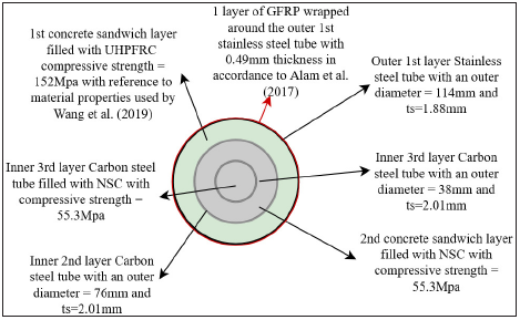
A schematic drawing has been shown in Figure 2 of the CFTST cross section with the new modification and material properties for specimens with an addition 3rd internal tube (D=38mm). As can be seen in Figure 2, the model consists of three steel tubes. The first layer outer steel tube is made from stainless steel with an outer diameter of 114mm with a tube thickness of 1.88mm.On the other hand, the second layer inner steel tube is made from carbon steel with an outer diameter of 76mm and a thickness of 2.01mm. Moreover, the third layer inner steel tube represents the additional proposed steel skin is made from carbon steel with an outer diameter of 38mm and tube thickness of 2.01mm. Furthermore, the first concrete fill sandwich layer between the outer stainless steel tube and the inner second layer carbon steel tube will be filled with Ultra High Performance Fiber Reinforced Polymer (UHPFRC). Besides the compressive strength of the UHPFRC will be 152MPa with reference to the material properties used by Wang et al. [4,5]. Contrariwise, the second concrete fill sandwich layer between the inner second layer carbon steel tube and the inner third layer carbon steel tube will be filled with Normal Strength Concrete (NSC)-compressive strength of 55.3MPa. Also, the inner third layer carbon steel tube will be filled with Normal Strength Concrete (NSC)-compressive strength of 55.3MPa. At the end, the outer stainless-steel tube will be wrapped with one layer of GFRP with an elastic modulus of 23GPa, a tensile strength of 508MPa and a thickness of 0.49mm with reference to the material properties indicated by Alam et al. [3]. Besides, the GFRP layer will be glued to the outer stainless-steel tube using adhesive. Finally, all the numerically analyzed specimens has a standard length of 1800mm.
Figure 2: Schematic sketch of the proposed CFTST cross section with the new design modification scheme (one GFRP layer) and material properties for specimens with an addition 3rd internal tube (D=38mm).

This design modification in Figure 2 will represent simulation numbers 115 to 120 with variations in magnitude of axial load, drop height and impact energy. For example, simulations number 115 and 116 will be axially load with a magnitude of 317kN, the drop height will be set at 3m and the impact energy will be 6kJ. While simulation numbers 117 and 118 will be axially loaded with a magnitude of 190kN, the drop height will be set at 5m and the impact energy will be around 10kJ. Furthermore, simulation numbers 119 and 120 will not be axially loaded, the drop height will be set at 7m and the impact energy will be 14kJ. Moreover, the drop mass will have the same magnitude for all the simulations with a value of 203.7Kg. Finally, the geometry of the bottom surface of the drop hammer indenter is rectangular and with a parameter of 30mm by 80mm [6,7].
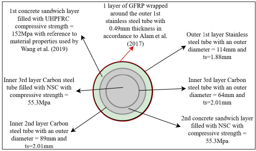
A schematic drawing has been shown in Figure 3 of the CFTST cross section with the new modification and material properties for specimens with an addition 3rd internal tube (D=64mm). As can be seen in Figure 3, the model consists of three steel tubes. The first layer outer steel tube is made from stainless steel with an outer diameter of 114mm with a tube thickness of 1.88mm. On the other hand, the second layer inner steel tube is made from carbon steel with an outer diameter of 89mm and a thickness of 2.01mm. Moreover, the third layer inner steel tube represents the additional proposed steel skin is made from carbon steel with an outer diameter of 64mm and tube thickness of 2.01mm. Furthermore, the first concrete fill sandwich layer between the outer stainlesssteel tube and the inner second layer carbon steel tube will be filled with Ultra High-Performance Fiber Reinforced Polymer (UHPFRC). Besides the compressive strength of the UHPFRC will be 152MPa with reference to the material properties used by Wang et al. [4,5]. Inversely, the second concrete fill sandwich layer between the inner second layer carbon steel tube and the inner third layer carbon steel tube will be filled with Normal Strength Concrete (NSC)- compressive strength of 55.3MPa. Also, the inner third layer carbon steel tube will be filled with Normal Strength Concrete (NSC)- compressive strength of 55.3MPa. At the end, the outer stainlesssteel tube will be wrapped with one layer of GFRP with an elastic modulus of 23GPa, a tensile strength of 508MPa and a thickness of 0.49mm with reference to the material properties indicated by Alam et al. [3]. Besides, the GFRP layer will be glued to the outer stainless-steel tube using adhesive. Finally, all the numerically analyzed specimens has a standard length of 1800mm.
This design modification in Figure 3 will represent simulation numbers 121 to 126 with variations in magnitude of axial load, drop height and impact energy. For example, simulations number 121 and 122 will be axially load with a magnitude of 142kN, the drop height will be set at 3m and the impact energy will be 6kJ. While simulation numbers 123 and 124 will not be axially loaded, the drop height will be set at 5m and the impact energy will be around 10kJ. Furthermore, simulation numbers 125 and 126 will be axially loaded with a magnitude of 237kN, the drop height will be set at 7m and the impact energy will be 14kJ. Moreover, the drop mass will have the same magnitude for all the simulations with a value of 203.7Kg. Finally, the geometry of the bottom surface of the drop hammer indenter is rectangular and with a parameter of 30mm by 80mm.
Figure 3: Schematic sketch of the proposed CFTST cross section with the new design modification scheme (one GFRP layer) and material properties for specimens with an addition 3rd internal tube (D=64mm).

The meshing and elements for circular hybrid triple skin
stainless steel tubular columns filled with UHPFRC and externally
strengthened with GFRP under transverse impact load investigation
will be conducted in accordance to the properties stated by Zhao et
al. [2]. Furthermore, the meshing has been divided into four parts
(1) CFDST elemenet, (2)supports, (3)drop hammer and (4)FE
model. The numerical meshing and elements of the new proposed
design scheme part for circular hybrid triple skin stainless steel
tubular columns filled with UHPFRC and externally strengthened
with GFRP under lateral impact load will be as follows:
A. The mesh for the outer first layer stainless steel tube, the
inner second layer carbon steel tube and the inner third layer
carbon steel tube will be simulated using S4R 4-node shell
elements.
B. The mesh for both UHPFRC and NSC sandwich and core
layers will be simulated using C3D8R 8-node solid element.
C. The mesh for the adhesive layer will be built using C3D8R
8-node solid element.
D. The mesh for GFRP will be built using S4R 4-node shell
elements.
With reference to Zhao et al. [2], the mesh for supports will be built using R3D4 4-node quadrilateral rigid element. Again, as recommended by Zhao et al. [2], the mesh for drop hammer was built using R3D4 4-node quadrilateral rigid element.
This proposed modification designs in Figures 1-3 will represent simulation numbers 109 to 114 with variations in magnitude of axial load, drop height and impact energy. For example, simulations number 109 and 110 will not be axially load, the drop height will be set at 3m and the impact energy will be 6kJ. While simulation numbers 111 and 112 will be axially loaded with a magnitude of 343kN, the drop height will be set at 5m and the impact energy will be around 10kJ. Furthermore, simulation numbers 113 and 114 will be axially loaded with a magnitude of 206kN, the drop height will be set at 7m and the impact energy will be 14kJ. Moreover, the drop mass will have the same magnitude for all the simulations with a value of 203.7Kg. Finally, the geometry of the bottom surface of the drop hammer indenter is rectangular and with a parameter of 30mm by 80mm.
In the opinion of the author of this manuscript, the new design
modification scheme on the specimens which were carried out
by Zhao et al. [2] and modified by Abdel Rahim [1], the hybrid
triple skin stainless steel tubular columns filled with UHPFRC and
externally GFRP-Jacketed will improve both the local and the global
performance of the structural member under lateral impact load.
Accordingly, this opinion paper discusses three noval aspects as
below:
a) Extending double skinned CFST into triple skinned CFST.
b) Using a combination of hybrid materials in the design
modification scheme. For example, (1) installation of stainless
and carbon steel tubes, and (2) Including filling Normal Strength
Concrete (NSC) and Ultra-High-Performance Fiber Reinforced
Concrete (UHPFRC) in the same design modification scheme.
c) Externally jacketing the new design modification scheme
with Glass Fiber Reinforced Polymer (GFRP).
References
- Abdel Rahim KAN (2021) Literature review: Concrete Filled steel tubes under transverse impact loading. Current Trends in Civil & Structural Engineering 7(3).
- Zhao H, Wang R, Hou C, Lam D (2019) Performance of circular CFDST members with external stainless-steel tube under transverse impact loading. Thin-Walled Structures 145: 106380.
- Alam MI, Fawzia S, Zhao XL, Remennikov AM, Bambach MR, et al. (2017) Performance and dynamic behaviour of FRP strengthened CFST members subjected to lateral impact. Engineering Structures 147: 160-176.
- Wang W, Wu C, Li J, Liu Z, Lv Y (2019) Behavior of ultra-high-performance fiber-reinforced concrete (UHPFRC) filled steel tubular members under lateral impact loading. International Journal of Impact Engineering 132: 103314.
- Wang W, Wu C, Liu Z (2019) Compressive behavior of hybrid double skin tubular columns with ultra-high-performance fiber-reinforced concrete (UHPFRC). Engineering Structures 180: 419-441.
- Abdel Rahim KAN (2021) Numerical modelling of the behavior of steel-concrete composite columns of different types of circular cross section subject to lateral impact. Civil Engineering Research Journal 11(5): 555825.
- Abdel Rahim KAN (2021) Circular double skin stainless steel tubular column filled with UHPFRC subjected to impact load. Global Journal of Civil Engineering 2: 1-11.
© 2022 Khalid Abdel Naser Abdel Rahim. This is an open access article distributed under the terms of the Creative Commons Attribution License , which permits unrestricted use, distribution, and build upon your work non-commercially.
 a Creative Commons Attribution 4.0 International License. Based on a work at www.crimsonpublishers.com.
Best viewed in


.jpg)


 Editorial Board Registrations
 Submit your Article
 Refer a Friend
 Advertise With Us
.jpg)


.jpg)


.bmp)
.jpg)
.png)
.jpg)


.jpg)


.png)

.png)


.png)


