
- About Us
- Information
-

The Author ensures that the research has been conducted responsibly and ethically with adherence to all relevant regulations. read more..
- For Authors
- For Reviewer
- Manuscript Guidelines
- Membership
- Publication Ethics
-
- Journals
- Reprints
- e-Books
- Videos
- Policies
- Contact Us
 COVID-19
- Submissions


Full Text
Advancements in Civil Engineering & Technology
Elasto-Plastic Behavior of Soil Foundation in Integral Abutment Bridges under Dynamic Load and Variable Degrees of Saturation
Jafar Razmi* and Leila Ladani
Ira A Fulton School of Engineering, Arizona State University, USA
*Corresponding author: Jafar Razmi, Ira A Fulton School of Engineering, Arizona State University, Tempe, Arizona, USA
Submission: July 23, 2020;Published: August 14, 2020

ISSN: 2639-0574 Volume4 Issue3
Abstract
Mechanical properties of the soil are function of many parameters. Moisture content is one of the key factors that impact the soils’ mechanical properties. Soil-pile interaction and pile displacement in bridges can, therefore, be impacted by the moisture content. Pile displacement in Integral Abutment Bridges (IABs) due to daily and seasonal temperature variations is a problem that has been under investigation. IABs do not have joint and as a result all the load and deformation in the slab is transferred to piles. If piles are deformed beyond their yield point, plastic deformation can occur. Due to the cyclic nature of the temperature variations, this cyclic load can result in cyclic mechanical fatigue in piles and eventually failure due to this phenomenon. The objective of this study is to a new computational approach to evaluate the moisture content effect on the interaction of pile and soil and the resulting pile displacement. This computational approach uses ANSYS APDL language to repeatedly change the moisture content of the soil and adjust the properties and compute the displacement in the piles. It is shown that increasing the moisture content decreases several key parameters such as bulk density, young’s modulus, cohesion and Poisson’s ratio. The simulation results indicate higher displacements as the moisture content increases. This behavior can be explained by decreased elastic modulus. As a result, soil behaves more flexible and allows more displacement of the pile.
Keywords: Mechanical properties of the soil; Cyclic load; Moisture content; Elastic modulus; Soil-pile interaction
Introduction
Figure 1: (a) Schematic drawing of a normal bridge with joints, (b) Schematic drawing of an IAB.

Soil-pile interaction is a topic that has been under investigation for many years. The challenges involved with understanding this interaction include the physical behavior of soil including the granularity of it, the impact of the water content which causes the soil particles to behave differently, the type of load on the pile, pile material etc. This phenomenon is particularly important in Integral Abutment Bridges (IABs). As opposed to normal bridges that use flexible joints to allow the expansion and contraction of the slab, IABs don’t have joints as shown in Figure 1. This means that all the expansion and contraction of the slab transfers to the abutment and consequently to the piles. This causes large displacement and sometimes large deformation of the piles. The amount of deformation in the piles depends on many factors including the length of the bridge, the type and material of the piles, the type of soil, the extent of temperature variation that occurs during the day and night and over several seasons, bridge material, type of soil and soil moisture content. The previous studies [1-6], have shown that deformation in piles can be so significant that can cause failure within the first decade of the life of the bridge.
However, previous studies neglect the effect of moisture in pilesoil interaction. As shown in the introduction, moisture can significantly change the mechanical properties and therefore impact the pile displacement and deformation [7]. This study aims to investigate this effect through simulation and modeling. In this Paper we will discuss the impact of moisture content on the mechanical properties. We will develop the analytical relationship between the moisture content and soil parameters. At the next step, a finite element simulation model of an Integral Abutment Bridge under extreme condition is used to computationally evaluate impact of the moisture and consequently mechanical behavior of the soil in an actual application. Pile displacements due to daily and seasonal temperature variations are obtained from the finite element simulation and compared for range of moisture content.
Variation of Soil Mechanical Properties
Soil is a granular material that behaves very differently from solid material as it has a complex set of mechanical properties [8]. Due to the granular nature of the soil, moisture can hugely impact how soil behaves in different circumstances including under mechanical load. As soil moisture increases, water fills the voids in between the granular particles of the soil. This impacts the interlocking between the particles and therefore, it impacts the shear strength and failure of the soil. The shear strength of the soil is a function of two parameters, cohesion and angle of friction as shown in the following equation:
In this equation, is the shear strength of the soil, c is the cohesion, is the normal stress and is the friction angle. Several researchers investigated impact of moisture content on these properties. It has been shown that increasing the moisture content can result in reduction in cohesion [9-12]. In a recent study conducted by Mouazen et al. [13,14] a triaxial test was conducted to understand the impact of moisture content on bulk density, elastic modulus, cohesion and friction angle. It was shown that bulk density is a linear function of moisture content as shown in Figure 2. The equation that relates the bulk density to the moisture content according to Figure 2 is:
In this equation w is the moisture content and is the bulk density [15] analysis of different of soil with a range of bulk densities at different moisture content level using three different confining pressures, showed that elastic modulus, cohesion and Poisson’s ratio are also function of both bulk density as well as the moisture content [15,16]. The equations for these three parameters are provided below:
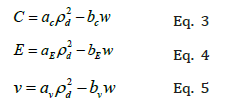
Figure 2: Field data for variation in dry bulk density with moisture content for sandy loam soil [15].

In these equations w is the moisture content and rd is the bulk density. C is the cohesion; E is elastic modulus and n is the Poisson’s ratio. The other parameters are constants that are calculated empirically for the types of soil shown in Figure 2. These constants are provided in the Table 1. Given that the bulk density is a function of moisture content, these equations can be transformed into the following equations as only function of moisture content:
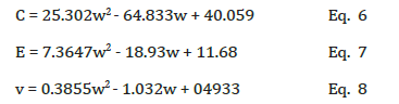
Table 1: Empirical constants used in Eqs 3-5 [15].

As seen in these equations, cohesion, elastic modulus and Poisson’s ratio are all second order function of moisture content. Figure 3-6 show plots of these parameters. The second order parameter of these functions is very weak in comparison to the linear effect. In other words, these figure all behave almost linearly. The same analysis showed that friction angle does not change with moisture content [15]. In modeling the soil interaction with piles or underground structures, often an elasto-plastic model such as Drucker-Prager model is used [17]. The Drucker-Prager material model is used for pressure-dependent inelastic behavior of materials such as soils, rock, concrete, and powder. The extended Drucker-Prager model is meant to address some shortcomings of the basic Drucker-Prager model-namely, the use of perfectly plastic behavior. A linear yield surface and a linear flow potential are used in this simulation. For extended Drucker-Prager model a yield function is defined as follows [14,18]:
Figure 3: Polynomial fit for Cohesion as second order function of moisture content.

Figure 4: Polynomial fit representing second order function of modulus of elasticity as function of moisture content.

Figure 5: Polynomial representing second order function for Poisson’s ratio as function of moisture content.

Figure 6: Cross section of the bridge slab, girders, and cross bracings.

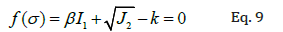
k and b are material constants, I1 is the first variant of the stress tensor (I1= 3sm, where sm is the mean stress or hydrostatic pressure), J2 is the second invariant of the stress tensor [19-21] defined as:
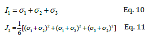
The values of k and β are calculated using c (soil cohesion) and ϕ (friction angle) as follows:
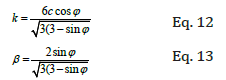
As seen in Eq. 12 and 13, b and k are function of c and j. However, j remains unchanged for the range of moisture content tested in this analysis. But c does change non-linearly with the moisture content. Substituting the equation for cohesion into Eq. 12, will result in k function as follows:
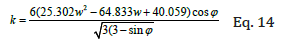
These functions are used in finite element to update the mechanical properties for each value of moisture content that is examined.
Finite Element Modeling
Bridge analyzed
The IAB studied in this paper is located in Rocky Mountains and experiences large daily and seasonal temperature variations. The cross section of the IAB modeled in this study is provided in Figure 6. The bridge length is considered 1800ft (548.64m) with the span of 50ft (15.24m). Eleven HP10X42 piles positioned with bending occurring around their strong axis are supporting the bridge abutment. The piles are placed such that the bending occurs around their strong axis. More details on the model is provided in Figure 7.
Thermal and mechanical loads
Thermal load is causing expansion and contraction of the bridge. This is caused by the variation in daily and seasonal temperature of the region. There is also mechanical load caused by the traffic load. To apply these random loads on the bridge, a mathematical model is needed. The details of these models are provided in Razmi [5]. The mathematical model for daily temperature variations is:
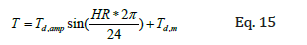
Where Td, amp is daily temperature amplitude and Td, m is the average daily temperature. HR varies between zeros to twenty-four (indicative of 24 hours of the day). The seasonal temperature variation is also modeled using the same sinusoidal model.
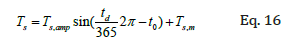
Where Ts, amp is the seasonal temperature amplitude and Ts, m is the seasonal mean temperature and td represents the number of the day for which the temperature is calculated. It varies between one to 365 days and t0 is an adjustment factor that can be varied to match the model to historical data. For the data, the seasonal maximum temp is 93 °F ,(33.88 °C) and the seasonal minimum is -17 °F , (-27.22 °C) thus Ts, amp is 38 °F, (3.33 °C ) and Ts, m is 55 °F, (12.77 °C)
To apply the traffic load, the AASHTO HL93 (Figure 8) designation according to AASHTO (American Association of State Highway and Transportation Officials) is considered. The FEMs are conducted using this design guideline using the design truck of (AASHTO HL93, [22]). To maximize the effect of the live load, the center of gravity of the truck is placed in the middle of the structure [23].
Figure 7: (a) Top view of the abutment showing the piles location and axis of rotation. (b) 3D FEM pile and abutment section. (C) Piles are oriented such that as thermal load is applied, they rotate around their strong axis.

Material properties
Table 2: Elastic properties of concrete and steel.

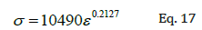
Three different types of material are used in the model: concrete, steel and soil. Concrete is used for the bridge slab and abutment. Steel makes the girders, cross bracing and piles and soil surrounds the piles beneath the abutment. Concrete is modeled as elastic material, while steel is modeled as elasto-plastic material. Soil is modeled using elasto-plastic Drucker-Prager model. Linear elastic properties of steel and concrete are shown in Table 2. For the soil, the linear elastic properties are varied based on the moisture content. The moisture content is varied between 0-30% and elastic modulus; Poisson’s ratio and cohesion are calculated using Eq. 6-8. These values are listed in Table 3: Some properties that are assumed to be constant are listed in Table 4: As for the non-linear behavior, the steel is considered to follow a power law equation as shown below.
Table 3: Calculated elastic modulus, cohesion and Poisson’s ratio for a range of moisture content./p>

In this equation s represents stress and e is the total strain as follows:
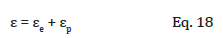
Where ee is the elastic strain and ep is the plastic strain. This equation is provided point by point to ANSYS.
Table 4: Soil parameters considered independent of moisture.

The soil is modeled as sandy loam using the Extended Drucker-Prager. The Drucker-Prager material model is used for pressure-dependent inelastic behavior of materials such as soils, rock, concrete, and powder. The Extended Drucker-Prager model is meant to address some shortcomings of the basic DP model- namely, the use of perfectly-plastic behavior. A linear yield surface and a linear flow potential are used in this simulation. Nonlinear properties of the soil are also function of moisture content. The properties needed for ANSYS are k and b according to Eq. 12-13. Since the friction angle does not change with moisture content, b which is only a function of friction angle will not change with moisture. k, however, is a function of both friction angle and cohesion and since cohesion varies with moisture content, k changes accordingly as shown in Table 5.
Table 5: dependency of k parameter and moisture content.

Figure 8: Distribution of AASHTO HL93 loading on the IABs.

Finite element model
Due to the size of the bridge modeling the whole superstructure and substructure is computationally extensive. However, we can utilize symmetry such that only a quarter of the bridge is modeled. A 3D non-linear model is built using ANSYS. The entire model is meshed utilizing map mesh and using hexahedral elements. Relatively thinner components such as slabs, piles, and girders are meshed using a two-dimensional shell element (SHELL181). For this element, the capability exists to define the thickness according to the real application. Mostly used for moderately thick shell structures, SHELL181 is a four-node element with six degrees of freedom at each node: translations in the x, y and z directions, and rotations about the x, y and z axis. Cross bracing was modeled using a one-dimensional beam element (BEAM188). BEAM188 is suitable for analyzing slender to moderately stubby/thick beam structures. The element was based on Timoshenko beam theory, which includes shear-deformation effects. BEAM188 has six degrees of freedom at each node. These include translations in the x, y and z directions and rotations about the x, y and z axis. The soil sections in the bridge are modeled using three-dimensional twenty-node solid elements of SOLID185. The element has the capability to model elastic, plastic and creep deformations.
The geometry and the boundary conditions are shown in Figure 9. Since only a quarter of the bridge is modeled, symmetry boundary conditions are applied on the symmetry planes: z = 0 on symmetry surface 1 and x = 0 on symmetry surface 2. The bottom of the soil is fixed in the y and z directions to simulate an end bearing type pile. Gravity is applied in the y direction. The piles are surrounded by soil in back and front with thickness of 3ft (0.9144m) in positive z direction and 10ft (3.048m) in negative z direction. Assuming that these soil layers are thick enough, the free surfaces of the soil are assumed to be stationary in the z direction, as the piles move. Therefore, the displacement perpendiculars to these free areas (displacement in the z direction) are assigned zero value as the boundary condition. Since all the elements are either 4-node, 8-node or 20-node elements, they are all compatible and there is no need for intermediate elements between different parts of the bridge. The number of elements for the whole structure (superstructure and substructure) is 285,000. Supports are provided at every 50ft (15.24m) underneath the slab to support the slab in the y direction. Therefore, displacement in the y direction is assigned a value of zero at these supports.
Figure 9: Geometry of the quarter of the bridge, and the boundary conditions.

Results and Discussion
Figure 10 shows the finite element results of pile displacement for the bridge at maximum daily temperature. This displacement changes depending on the temperature load of the model during 24 hours and 12 months. Additionally, it also varies for different piles and along the length of the pile as can be seen in this figure. For the purpose of this analysis, we are only interested in the maximum and minimum values of the displacement. Maximum and minimum displacements occur in the pile that is at the edge of the bridge and furthest from the center of the bridge. As seen in this figure the displacement also depends on the depth. It is found that the maximum displacement occurs under the abutment in depth. The pile displacements are obtained at both maximum and minimum daily temperatures and maximum and minimum seasonal temperatures. The results are shown in Table 6.
Table 6: FEA results for maximum displacements in piles due at max and min daily and max and min seasonal temperatures for variety of moisture contents.

Figure 10: (a) Drawing of pile deformation in 30% humidity as function of depth, (b) FE results of pile displacement.

Figure 11: Max and min daily and seasonal displacement in piles as a function of moisture content.

As observed by these values, all the displacement values have an increasing trend as the moisture content is increasing. This trend is shown for all four displacements in Figure 11. This trend could be explained through several factors. As the moisture content increases, the elastic modulus of soil decreases according to the initial analytical illustration, hence making the soil more flexible allowing the piles to move further as the slab pushes or pulls against them. Additional effects can be caused by the impact of Drucker-Prager yield function. The impact can be explained by the factor k which defines how large the stresses need to be in order for the yield to occur. As the moisture increases, this value decreases which in turn indicates that soil can deform plastically at lower stress levels. This again allows the soil to deform further and non-linearly allowing the displacements of the piles to increase. Therefore, the impact of moisture can become significant in cases where moisture can impact these parameters significantly.
Although very important in design of IABs, displacement alone cannot be used to predict the life expectancy of the piles. That depends on the stresses that develop in piles. In particular, one specific type of stress, Von-Misses stress, which dictates whether the structure experiences plastic deformation, is often used for examining structural failure as shown in the following equation [24]:

Where: , , XX YY ZZ σ σ σ are normal stress component and yz, xz, xy τ τ τ are the shear stress components.
Figure 12: The von-misses stress distribution in piles at (a) maximum and (b) minimum daily temperature.

This stress is shown for maximum and minimum daily temperatures in Figure 12. As it can be seen in this figure, the stress varies tremendously throughout the piles. Some regions experience large amounts of stress which could exceed the yield strength of the piles resulting in plastic deformation and failure. The stresses are largest in the pile that is at the edge of the bridge and furthest from the center. Even in that pile, stresses vary largely depending on the depth of the pile. As expected, based on values of displacement, maximum stress also occurs below the abutment. The values of the maximum stress which occurs at the maximum daily and seasonal temperatures are plotted against moisture content in Figure 13.
Figure 13: Maximum stress observed in the piles at maximum daily and seasonal temperature.

As seen in this figure, these values decrease as the moisture content increases. This variation seems to be logical, because as the soil becomes more compliant and allows the piles to displace larger, the piles deformation due to the moment decreases which causes the stresses to reduce in the piles. In other words, the total displacement in slab has to manifest itself in two fractions. The first fraction is the soil deformation that is shown through pile displacement and the second fraction is the pile deformation. As the soil becomes more compliant due to higher moisture content, it deforms easier imposing less pressure on the piles. Therefore, the pile curvature and deformation due to moment decreases resulting in lower stresses in piles. The final conclusion that one can make may be that higher moisture content can help with reducing the stresses on piles. Lower stresses can result in longer life expectancy under thermos-mechanical cyclic load due to daily and seasonal temperature variations.
Summary and Conclusion
A comprehensive, 3D non-linear finite element simulation of an IAB bridge located in a harsh environment under seasonal and daily temperature variations is conducted. To understand the impact of moisture content on bridge behavior, pile displacement and stresses developed in the piles, the moisture content of the soil is varying and accordingly the mechanical properties of soil is updated. The results show that as the moisture content increases the displacement of the piles increase. This is attributed to the increased flexibility of the soil due to higher moisture content and decreased yield strength due to decreased k factor.
Further analysis of stresses observed in the piles, indicate that piles may experience lower stresses at higher moisture content. This is attributed to the lower pressure imposed by the soil on the piles as the pile move and deform. Majority of the slab displacement is transferred to soil deformation rather than pile deformation resulting in lower stresses in piles. This indicates higher life expectancy for piles at higher moisture content.
Data Availability Statement
Some or all data, models, or code generated or used during the study are proprietary or confidential in nature and may only be provided with restrictions. (Finite Element models are restricted due to licensing and Intellectual Properties restrictions).
References
- Razmi J, Aggour MS (2014) Performance of piles in integral abutment bridges under thermo-mechanical cyclic loads. Journal of Bridge Structures 10: 11-17.
- Razmi J, Aggour MS (2014) Finite element simulation of pile behavior under thermo-mechanical loading in integral abutment bridges. Journal of Structure and Infrastructure Engineering 10(5): 643-653.
- Razmi J, Aggour MS (2013) Fatigue life analysis of piles in integral abutment bridges, a case study. Journal of Bridge Engineering 18(10): 1105-1117.
- Razmi J, Aggour MS (2013) Fatigue crack initiation and propagation in piles of integral abutment bridges. Computer-Aided Civil and Infrastructure Engineering 28(5): 389-402.
- Razmi J (2016) Fracture mechanics-based and continuum damage modeling approach for prediction of crack initiation and propagation in integral abutment bridges. Journal of Computing in Civil Engineering 30(4).
- Razmi J (2016) Comparison of fracture mechanics and continuum-based damage modeling approach in determining the crack path in piles of integral abutment bridges. International Conference on Fatigue Damage of Structures Materials XI, Massachusetts, USA.
- Krishnapillai H, Ravichandran S (2012) Soil-water characteristic curve and its performance in the finite-element simulation of unsaturated soils. International Journal of Geomechanics 12(3).
- Swain A, Ghosh P (2019) Determination of viscoelastic properties of soil and prediction of static and dynamic response. International Journal of Geomechanics 19(7).
- Chancellor WJ (1971) Effects of compaction on soil strength. In: Barnes KK, Carleton WM, Taylor HM, Throckmorton RI, VandenBerg GE (Eds.), Compaction of Agricultural Soils. SAE, St. Joseph, Michigan, USA.
- Kezdi A (1974) Handbook of soil mechanics. Soil Physics. Elsevier Sciences, Amsterdam, Volume 1.
- Porter MA, McMahon TA (1990) MUTILLS- The Melbourne university tilled soil model. Transactions of the ASAE 30(4): 888-892.
- McKyes E, Nyamugafata P, Nyamapfene KW (1994) Characterization of cohesion, friction angle and sensitivity of two hard setting soils from Zimbabwe. Soil and Tillage Research 29: 357-366.
- Mouazen AM (1997) Modelling the interaction between the soil and tillage tools. PhD Thesis, Hungarian Academy of Sciences, Budapest, Hungary.
- Mouazen AM, Nemeny M (1997) Application of the Drucker-Prager elastic-perfectly plastic. PANNON University of Agricultural Sciences, Faculty of Mosonmagyarovar, Department of Agricultural and Environmental Engineering, H-9200 Mosonmagyarovar, Hungary.
- Mounem M, Ramonb H, Baerdemaeker J (2002) Effects of bulk density and moisture content on selected mechanical properties of sandy loam soil. Biosystems Engineering 83(2): 217-224.
- Wang T, Zhou G, Wang J, Yin L (2018) Stochastic thermal-mechanical characteristics of frozen soil foundation for a transmission line tower in permafrost regions. International Journal of Geomechanics 18(3).
- Borana L, Yin JH, Singh DN, Shukla SK (2017) Influences of initial water content and roughness on skin friction of piles using FBG technique show all authors. International Journal of Geomechanics 17(4).
- Mizuno E, Chen HF (1980) Plasticity models for soils, CE-STR-80-l2, School of Civil Engineering, Purdue University, West Lafayette, Indiana.
- Ladani L, Razmi J (2009) An anisotropic mechanical fatigue damage evolution model for Pb-free solder materials. Mechanics of Materials 41(7): 878-885.
- Ladani L (2007) Damage initiation and evolution in voided and unvoided lead free solder joints under cyclic thermo-mechanical loading. PhD Dissertation, University of Maryland, College Park, Maryland.
- Ladani L (2015) Local and global mechanical behavior and microstructure of Ti6Al4V parts built using electron beam melting technology. Metallurgical and Materials Transactions A 46(9): 3835-3841.
- AASHTO (2010) Standard specifications for highway bridges. IN: (5th edn), American 540, Association of State Highway and Transportation Officials, Washington DC.
- Greimann LF, Abendtroth RE, Johnson DE, Ebner B (1987) Pile design and tests for integral abutment bridges. Final Report, Iowa Department of Transportation, Project HR-273, Ames, Iowa, pp. 12-16.
- Ladani LJ (2010) Stress analysis of 3-dimensional IC package as function of structural design parameters. Microelectronic Engineering 87(10): 1852-1860.
© 2020 Jafar Razmi. This is an open access article distributed under the terms of the Creative Commons Attribution License , which permits unrestricted use, distribution, and build upon your work non-commercially.
Editor In Chief


.jpg)


Signup for Newsletter

Quick Links
 Editorial Board Registrations
 Submit your Article
 Refer a Friend
 Advertise With Us
Our Recent Edition

.jpg)


Top Editors


.jpg)


.bmp)
.jpg)
.png)
.jpg)


.jpg)


.png)

.png)


.png)


Financial Support

Sponsors

Latest e-Books

Latest Video

 a Creative Commons Attribution 4.0 International License. Based on a work at www.crimsonpublishers.com.
Best viewed in
a Creative Commons Attribution 4.0 International License. Based on a work at www.crimsonpublishers.com.
Best viewed in