- Submissions

Full Text
Advancements in Civil Engineering & Technology
A Case Studies to Estimate the Shearing Characteristics of a Natural Cemented Gravel Soil Trough Large in situ Direct Shear Test Flexural Strength of Concrete
Carlo G Ferretti*
Researcher and Professional geologist, Italy
*Corresponding author: Carlo G Ferretti, Geo Identity Research, Italy
Submission: October 09, 2019;Published: October 17, 2019

ISSN: 2639-0574 Volume3 Issue5
Abstract
In project of applied geotechnical engineering it is necessary to know the shearing characteristics of the soil in place. In some cases, it is not possible to recover intact samples, maintaining their representative mechanical properties and analyzing them in the laboratory. It is, therefore, necessary to carry out tests in situ to determine the mechanical characteristics of soil that are essential to project design. This article reports a practical case study on alluvial sediments with a coarse gravel sandy texture. For its appropriate analysis a large in situ direct shear test has been designed and performed. This technique identified the presence of a weak soil cementation by natural calcite and its important effect on geotechnical soil failure behavior. Moreover, the test stated the unusual shear characteristics for a granular soil-structure of alluvial origin, and the proper cohesion and friction angle values (C=36.9 kPa; ϕ= 52°) to consider in the project.
Keywords:In situ direct shear test; Gravel granular material; Natural cemented soil; Geo Identity Research
Introduction
The geological environment is represented by fluvioglacial sediments with natural cemented soils composed of clean gravel, with pebbles, sand and well-rounded grain shape. The traditional investigations, such as geo-gnostic surveys and excavations, alter mechanically the natural state of this soils removing the partial vadose cementation between grains and consequently sampled soil appear as loose granular material. Both the in situ and laboratory geotechnical tests can miscalculate or underestimate its shear characteristics, which are essential in designing projects. In this case also a small amount of cementation of soil was still of essential importance, because the project included the hydraulic thrust of a large concrete monolithic box into the ground and the soil strength properties play a critical role to the construction accomplishment. Therefore, to define the strength characteristics of materials, experimental large in situ direct shear test has been designed and performed. This publication presents a geological and hydrogeological description of the zone, the carried out direct shear test and its geotechnical results, with evaluation of the shear resistance of investigated soil.
Material and Methods
Site and geology description
This trial was conducted in Northern Italy, precisely at the GPS Coordinate: 45°25’37.3”N 10°56’50.6”E. From geological point of view the area belongs to the central part of the high Po Valley, which is characterized by well-defined geomorphological and hydrogeological features. It is a large portion of territory between the morainic hills of Garda Lake, on the West side, the northern massive carbonate from the chain of Lessini mountains and, on the south, the so-called water reviving line on the Pianura Veronese. The morphological distinctive element of this area is undoubtedly made up of the huge alluvial fan of the Adige River. It was formed in the Quaternary era by the input of massive quantity of debris material, transported by the river that stemmed from the great Pleistocene Alpine glaciers. The catchment basin of the Adige River is composed of many limestones Formations, which form a part of the Southern Limestone Alps complex. Water percolates through limestone and chalk during Quaternary periods were largely made up of calcium and magnesium carbonates. The re-deposition of this minerals in form of calcite cement in the porous sediment of the flood plain was so favored. From the hydrogeological point of view the area is composed of a single phreatic complex, whose piezometric surface is located between -50 m and -52 m below the surface [1,2]. The subsoils have been explored with geological surveys and its stratigraphy indicates a thick sediments layer of several decameters composed by gravel to gravelly-stony materials, with sporadic sandy matrix and local traces of silt. The grains that compose the subsoil are cemented by natural calcite with an open-porphyric pattern, in which the primary grains float in the expanding crystal matrix [3]. In this particular case ionicly bonded calcite forms a thin film coat that covers the grains at particle contact points, providing a weak cementation of the soil while this preserves a high level of porosity.
Analytical methods
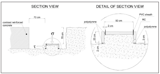
For the evaluation of the geotechnical soil properties following tests were performed: Classification of the material by soil particle size analysis and Atterberg limits according to standard CNR-UNI 10006 [4]; determination of bulk density in the site according to technical standard CNR n. 22 [5]; determination of the soil resistance parameters through direct shear test in the site according to ASTM D 4554 [6]. Regarding the latter, a large in-situ direct test was necessary to verify, direct in place and experimentally, the shearing features of the soil. Due to the lithological characteristics described above, undisturbed soil samples for laboratory analysis could not be taken in any way. A further problem was the representativeness of an eventual soil sample containing grains with dimension larger than then centimeter, that requires outsized and not normally available laboratory equipment. Thus, a sort of direct share box test has been assembled preserving the natural undisturbed soil inside of it (Figure 1). The size of the in situ tested samples was proportionate to that of the gravel present soil. The share box was assembled by a reinforced concrete casting that covers samples that were preventively excavate with high accuracy in soil. The direct shear test consists in subjecting the soil sample to two forces acting on orthogonal planes to each other, a vertical σ stress and a horizontal cutting τ stress, to verify its behavior till to the critical state. In consideration of the geological engineering problem of interest, shear tests were carried out in a low range of vertical load, which should reflect the stress state of the soil in real conditions.
Figure 1:Layout of the large in situ direct test.
Result and Discussion
Soil characteristics
The study of the grain size distribution curves classifies the soil as clean gravel (silty fine fraction <2.3%) with pebbles and sand, well sorted, hazel color with rounded to sub-rounded shape, weakly cemented and with strong reaction to hydrochloric acid. According to Unified Soil Classification System USCS [7] the soil corresponds to the group GP, poorly graded gravel. The Atterberg limits indicate instead: plastic limit PL= non-plastic; plastic index IP=0. An extremely reduced presence of silt-fraction was therefore confirmed, and this leads to the exclude any cohesive action provided by the soil fine-matrix. On site defined bulk density revealed the following values, typical of a dry compact soil: Dry bulk density: γd= 1,93 t/m3; Water content in its natural state: w=4.3 %.
Shear resistance
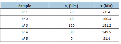
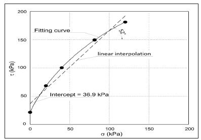
The stress-controlled tests were performed on a total of five samples and completed under drained condition. The shear characteristics have been defined with reference to the stress state recorded at the peak of the stress-strain curves (Table 1). To predict the shear strength in drained conditions the Mohr-Coulomb theory may be used [8]. In terms of effective stresses, the shear strength is often approximated using the equation: τ=c + σ tanϕ. Were “c” is called cohesion, ϕ is the angle of internal friction and σ is the total stress applied normal to the shear plan. As confirmation of the good result of the test carried out and the consequential reliability of the obtained data, it should be noted the curved trend of the experimental interpolation which passes through all the points defined by the shear tests (Figure 2). This in analogy with the curvature (nonlinearity) of the theoretical failure envelope that occurs because the dilatancy of closely packed soil particles on confining pressure. The intercept of the fitting curve on the τ shear stress axis represent the natural cohesion of soil we were evaluating.
Table 1:Recorded values of normal stress (σn) and the peak shear stress (τ) on the tested soil samples.
Characteristic shear strength parameter of soils like cohesion and friction angle could be extrapolated from the failure curve. A linear interpolation of data set bound to the minimum value of shear stress provide values of intercept and inclination respectively equal to c=21kPa and ϕ=55°. The natural morphology of the project location defines the presence of a modest lithostatic stress, due to the shallow depth under the surface of the underpass excavation. Therefore, in our real case the failure curve can be approximated to a straight line marked out in a normal stresses range close to that predicted in project (Figure 2). So, values of intercept and inclination provide values of cohesion C=36.9kPa and soil friction angle ϕ=52°. These values are significantly higher than those normally considered for loose ground, even if partially cohesive. Moreover, test samples contain only 2.3% of fine fraction <0.075 and so we can exclude the presence of cohesion for this poorly graded gravel soil [9-11]. Moreover, the tests confirmed the presence of a weak cementation that influences the constructive design techniques.
Figure 2:Representation on the σ-τ plane of the direct shear tests results.
Drained stress strain curves
Figure 3:Detail of the stress/strain behaviour with any normal stress applied on sample five.
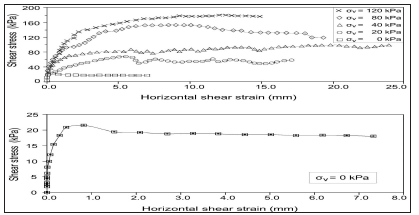
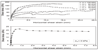
The weak cementation of soil, otherwise undetectable by geognostic routine analysis, is confirmed by the stress-strain curve of the sample number five (Figure 3), for which the test was performed with any normal stress. This curve describes the non-frictional part of the shear resistance which is independent of the normal stress, and the stress-strain response directly represent the strength of cemented material. In fact, by placing σ=0 in the Mohr-Coulomb equation (τ=c + σ tanϕ), the shear strength depends theoretically only on the cementation (τ=c). The curve shows in its initial part the absence of share strain, due to the resistance offered by the stiffness properties of the grain’s cementation. By increasing the shear stress produce a progressive failure of the ionic bonds that cement the soil grains, and the critical state is passing from elastic to elastoplastic, which drives volumetric changes in the sample. After that interparticle bonds are broken, a stress strain curve typical for a drained dilatant soil is shown, which is no more depending from the intergranular contact forces of cement. The presence of a substantial bonding action between grains offered by a weak carbonate cementation was therefore confirmed, and a smooth transition between the fully cemented zone and the fully plastic zone occurs [12]. The complete set of tests data are illustrated in Figure 4, where the stress strain curves appears often complicated by the non-uniformity of sample deformation [13]. But this should be considerate usual and not unique to the here described tests. The trial indicates moreover that the share strain range should be chosen carefully. Soil preconsolidation pressure should be applied with caution in such a brittle behavior, as not to favor the breakage of ionic bonds of the weak calcite cement even before the test start.
Figure 4:Shear Stress-Horizontal displacement curves under different normal stress. The initial elastic deformation is due to the cohesion effect of the calcite crystals in the sediment pore spaces. The overlap of all the curves in this first sector confirms the soil uniformity and the test consistency.
Conclusion
The behavior of a natural weak cemented gravel soil was investigated by carrying out a large in situ direct shear test. The applied method can be a practical tool to overcome the problems arising from the inability to test very coarse and cemented soils in the standard shear-box apparatus or using other classical in situ tests. Experimental results show a significant effect of cementation, influencing both the stress-strain behavior and the peak strength at strains beyond those required to fracture the cement bonding. The cementation increases the shear modulus and size of the yield locus, but little effect on initial volume change because of the weak grade of cementation was observed. Although the soil cementation strength was reduced, it was in practice able to hinder the directional forward translation of the concrete monolithic box, affecting the constructive design techniques. Exhaustive knowledges of the site and of its geological history should have been essential for the correct preliminary classification of subsoils and for the planning of geotechnical surveys. Tests conducted in the absence of such geological information may lead to improper estimation of the strength characteristics of the material, affecting the design and construction choices.
References
- Del Veneto R (1987) Geomorphological units map scale 1:250.000. National Geological Survey. SELCA. Florence, Italy.
- Del Veneto R (1988) Geological map of Veneto scale 1:250.000. National Geological Survey. SELCA. Florence, Italy.
- Chadwick OA, Nettleton WD (1990) Soil micromorphology: A basic and applied science. In: Duglas LA (Ed.), Elsevier ISBN 0-444-88302-9, pp. 207-212.
- CNR-UNI 10006 (1998) Road construction and maintenance, Land use techniques. Ministry of Environment Decree, p. 88.
- CNR 22 (1972) Apparent specific gravity of an in-situ CNR Official Bulletin IV, p. 15.
- ASTM D4554-12 (2012) Standard test method for in-situ determination of direct shear strength of rock discontinuities. ASTM International. West Conshohocken, USA.
- ASTM (2011) Standard practice for classification of soils for engineering purposes (Unified Soil Classification System). American Society for Testing and Materials ASTM International. West Conshohocken.
- Terzaghi K (1942) Theoretical Soil Mechanics. Wiley, New York, USA.
- NAVFAC (1986) Design manual 7.2-foundations and earth structures. SN 0525-LP-300-7071. Naval Facilities Engineering Command. Washington, USA.
- Swiss Standard SN 670 010b (2000) Characteristic coefficients of soils. Federal Institute of Technology in Lausanne. Lausanne, Switzerland.
- MnDOT (2007) Pavement Design Manual. Section 3.2 Subgrade Soils. Minnesota Department of Transportation. St. Paul, Minnesota, USA, p. 39.
- Lade PV, Trads N (2014) The role of cementation in the behavior of cemented soils. Geotechnical Research 1(4): 111-132.
- Liu MD, Airey DW, Carter JP, Xu JK (1999) Explicit stress-strain relations for an artificial cemented carbonate sand. In Pre-failure Deformation Characteristics of Geomaterials, Balkema. Rotterdam, Netherlands.
© 2019 Carlo G Ferretti. This is an open access article distributed under the terms of the Creative Commons Attribution License , which permits unrestricted use, distribution, and build upon your work non-commercially.
 a Creative Commons Attribution 4.0 International License. Based on a work at www.crimsonpublishers.com.
Best viewed in


.jpg)


 Editorial Board Registrations
 Submit your Article
 Refer a Friend
 Advertise With Us
.jpg)


.jpg)


.bmp)
.jpg)
.png)
.jpg)


.png)

.png)


.png)


