
- About Us
- Information
-

The Author ensures that the research has been conducted responsibly and ethically with adherence to all relevant regulations. read more..
- For Authors
- For Reviewer
- Manuscript Guidelines
- Membership
- Publication Ethics
-
- Journals
- Reprints
- e-Books
- Videos
- Policies
- Contact Us
 COVID-19
- Submissions


Full Text
Advancements in Civil Engineering & Technology
Evaluation and Strengthening of an Eight-Storey Existing Reinforced Concrete Building in Abha City, KSA
Mohammed Ismaeil1*, Ali Hassaballa2, Mohamed Y Laissy3, Isam Eldin Kamal3 and Fathelrahman Adam4
1 King Khalid University, KSA
2 jazan University, KSA
1,3 University of Prince Mugrin, KSA
4 Nile Valley University, Sudan
*Corresponding author: Mohammed Ismaeil, University of Prince Mugrin, KSA
Submission: January 03, 2019;Published: January 18, 2019

ISSN: 2639-0574 Volume2 Issue5
Abstract
Saudi Arabia’s kingdom is not free from seismic tremors. It has encountered numerous quakes amid the ongoing history, and the past investigations on this field exhibited this contention. Many existing structures in Abha City have not been intended to oppose seismic forces. Moreover, it is imperative to contemplate the reaction of these structures under seismic conditions. Likewise, there is a lack in the examinations done in this field identified with Abha City. Consequently, existing structures ought to be assessed with respect to their ability for opposing expected seismic impacts before recovery works. Investigation was completed by utilizing auxiliary examination program (SAP2000) [1] with the utilization of static technique proposed by the Saudi Building Code (SBC) [2] to decide the reaction of regular multi-storey structures made of strengthened cement because of quake ground loads.
Objective of this paper is to assess the execution of existing multi-storey RC working in Abha City under seismic loads. To accomplish this goal, a 3D model for eight-storey RC building was developed utilizing SAP2000 examination program, though tremor loads were determined by static technique. Outcomes got from this paper inferred that the present plan of existing structures in Abha city is dangerous for the present seismicity of Abha territory. At last, it has been verified that RC shear walls signified a truly reasonable procedure, as a fortifying method for existing RC structures, to lessen the seismic defenselessness of these structures.
Keywords: Kingdom of Saudi Arabia; Strengthening; Saudi building code (SBC); SAP2000; Seismic forces
Introduction
Seismic retrofitting is the change of existing structures to make them progressively impervious to seismic movement, ground movement, or soil failure because of tremors. Seismic tremor is the vibration of the earth’s surface that trails a sudden discharge of energy in the crust. Amid a tremor, the ground surface moves in every direction. The assessment of seismic execution of existing RC structures has gotten an incredible consideration in the most recent decade. The most harming impacts on structures are caused by horizontal activities which irritate the steadiness of the structure, making it topple or to fall sideways. Since structures are ordinarily developed to oppose gravity, numerous conventional frameworks of development are not characteristically impervious to horizontal forces.
Along these lines plan for seismic tremors comprises to a great extent of taking care of the issue of building vibrations. With better comprehension of seismic interest on structures and with our ongoing encounters with huge quakes close urban focuses, the need of seismic retrofitting is all around recognized. Preceding the presentation of current seismic codes in the late 1960s for created nations (US, Japan and so forth.) and late 1970s for some different parts of the world (Turkey, China and so on.), numerous structures were planned without sufficient specifying and fortification for seismic assurance [3]. A site visit will be led by the plan proficient to confirm accessible existing building information or gather extra information and to decide the state of the building and its parts [4]. The choice to reinforce and choice of the fortifying plan will be represented by the significance of the building, evaluated the cost of fortifying, interruption to the utilization of building and accessible innovation [5].This paper trying to examine the impact of seismic loads on existing RC structures in Abha city, Kingdom of Saudi Arabia.
Modeling and Analysis of Existing RC Buildings due to Gravity Loads
Description of the building
The considered working in this task is a run of the mill eightstorey RC healing facility working of both vertical and flat normal geometry situated in Abha city. The structure individuals are made of in-situ fortified cement. The general arrangement measurement is 21.5m x 31.5m. The tallness of the building is 28m. The cross segment of bars and sections appeared. The structured framework is a minute opposing RC outline with solid chunk arrangement of 150mm thickness. ABHA city is situated in seismic zone 6 (district 6) in Saudi Arabia seismic guide. The investigation of the building was completed utilizing the SAP2000 FEA program [2] because of vertical static stacking and quake stacking per the Saudi Building Code (SBC) [1]. The building is displayed as 3-D outlines with settled backings at the establishment level. Table 1 models the areas of sections and light emissions contemplated fabricating.
Table 1:Sections of columns and beams of the studied building.

Current design
It is a typical practice in the Kingdom of Saudi Arabia to structure structures with no thought of seismic loads. In this way, the one run of the mill building has been examined first under the impact of gravity loads and without thought of seismic loads so as to check the present structure. Dead and live loads are following the Equations and Tables given in the (Saudi Building Code).
Numerical model
Figure 1:Model of eight-storey building.

Figure 2:X-Y Plan of the studied building.

Numerical models for the considered case have been equipped utilizing SAP2000 form 14 [1]. Shafts and segments are displayed as bar components while walls are verified as shell components. Figure 1&2 show the model examined in this.
Results of analysis of considered building due to gravity loads
Figure 3:3D view of the selected frame XZ at Y=1.5.

Figure 4:3D view of the selected frame XZ at Y=11.5.

Figure 5:3D view of the selected frame YZ at X=1.5.

Figure 6:3D view of the selected frame YZ at X=19.5.

Figure 7:Label of columns for selected frame YZ.

Figure 8:Label of columns for selected frame XZ.

Figure 9:Label of beams for selected frame YZ.

Figure 10:Label of beams for selected frame XZ.

This part shows the consequences of Analysis of considered RC structures because of gravity loads. We chose two casing toward every path X and Y as appeared in Figure 3-6 for sections and shafts and Figure 7-10 models the mark of segments and light emissions chose outlines.
Straining Action of Some Columns and Beams Due to Gravity Loads
The occasions, shear and pivotal forces in the sections and shafts for the chose edges got from gravity loads are appeared in Table 2-5.
Table 2:The occasions, shear and pivotal forces on a few segments in the chose casings because of gravity load

Table 3:The moments and axial forces on some beams in the selected frames due to gravity loads.

Table 4:The straining action of some columns beams in the selected frames at direction Y-Z @ X = 1.5 & Y = 19.5.

Table 5:The moments and axial forces on some beams in the selected frames due to gravity loads.

The Straining activity of a few columns in the chose casings at heading X-Z @ Y = 1.5& Y = 11.5
Columns: Tables 2 models the stressing activity of a few segments
Beams: Table 3 shows the straining action of some due to gravity load
The straining action of some columns beams in the selected frames at direction Y-Z @ X = 1.5& Y = 19.5
Columns
Beams: Table 5 shows the straining action of some due to gravity loads
Modeling and Analysis of Existing RC Buildings due to Earthquake Loads (Equivalent Static Method as per SBC-303-2007)
This part is concentrating on the center of this undertaking (demonstrating and examination of considered Buildings because of seismic loads as indicated by (Saudi Building Code)). Most structures and structures in the kingdom of Saudi Arabia have not yet been planned and developed in consistency with seismic tremor arrangements or given any thought for quake impact (Table 6 & 7).
Table 6:Seismic parameter for ABHA City according to SBC301.

Table 7:Base Shear According to SBC301.

Earthquake loads
The tremor loads are determined after the principles which are given in the Saudi Building Code (SBC-303-2007) [1].
Types of seismic examination
There are distinctive strategies for investigation which gives a diverse level of exactness dependent on the sort of outer activity and conduct of the structure. Figure 11 models the kinds of seismic examination.
Figure 11:Type of seismic analysis [4].

Basic loads combinations [5]
Loads listed herein shall be considered to act in the following combinations; whichever produces the most unfavorable effect in the building, foundation, or structural member being considered. Effects of one or more loads not acting shall be considered.
D + F (Eq. 2.4.1-1)
D + H + F + L + T (Eq. 2.4.1-2)
D + H + F + (Lr or R) (Eq. 2.4.1-3)
D + H + F + 0.75 (L + T) + 0.75 (Lr or R) (Eq. 2.4.1-4)
D + H + F + (W or 0.7E) (Eq. 2.4.1-5)
D + H + F + 0.75 (W or 0.7 E) + 0.75 L + 0.75 (Lr or R) (Eq. 2.4.1-6)
0.6D + W + H (Eq. 2.4.1-7)
0.6D + 0.7E + H (Eq. 2.4.1-8)
Where D = dead loads, H = horizontal loads, L= live loads, Lr = live loads on roofs …etc.
The most unfavorable effects from both wind and earthquake loads shall be considered, where appropriate, but they need not be assumed to act simultaneously. Refer to Section 9.3 of SBC-303- 2007 for the specific definition of the earthquake load effect E.
Seismic loads according to Saudi building code (SBC- 303-2007)
The horizontal seismic loads are defined according to Saudi Building Code (SBC-303-2007). The lateral force effect on the structure can be translated to equivalent lateral force at the base of the structure which can be distributed to different stories. According to Saudi Building Code (SBC-303-2007), the total seismic base shear force V is determined as follows:
V = Cs*W (1)
Where: Cs is the seismic coefficient, W is the total weight and V is the base shear. The seismic design coefficient (Cs) shall be determined in accordance with the following equation:
Cs = SDS / (R / I) (2)
Where, SDS = Design spectral response acceleration in the short period range
R = Response modification factor
I = Occupancy importance factor determined
The value of the seismic response coefficient, (Cs), need not be greater than the following equation:
Cs = SD1 / [T. (R / I)] (3)
But shall not be taken less than.
T = 0.1N (4)
Where N = Number of stories
Cs = 0.044SDSI (5)
Where, SDS = Design spectral response acceleration at a period of 1 sec
T = Fundamental period of the structure (sec)
Design earthquake spectral response acceleration at short periods, SDS, and at 1-sec period, SD1, shall be as follows.
SMS= Fa*SS (6)
SM1= Fv*S1 (7)
SDS= 2/3*SMS (8)
SD1= 2/3*SM1 (9)
Where:
SS: the maximum spectral response acceleration at short periods
S1: the maximum spectral response acceleration at a period of 1 sec
Fa: acceleration-based site coefficient
Fv: velocity-based site coefficient
SMS: the maximum spectral response acceleration at short periods adjusted for site class
SM1: the maximum spectral response acceleration at a period of 1 sec adjusted for site class
SDS: the design spectral response acceleration at short periods
SD1: the design spectral response acceleration at a period of 1 sec
Mapped acceleration parameters
The design parameters that are used in the equivalent static method are illustrated as following: The parameters Ss and S1 shall be determined from the 0.2 and 1 second spectral response accelerations shown on country maps
Where S1 is less than or equal to 0.04 and Ss is less than or equal 0.15, the structure is permitted to be assigned to seismic design category A So,
S1= the mapped spectral accelerations for a 1- second period
Ss= the mapped spectral accelerations for short period.
On lack of a map of spectral accelerations of S1 and SS, the following can be assumed: S1= 1.25 Z, Ss= 2.5 Z (amendment no. 3 to SI 413 (2009)) [6] or from maps as shown in Figure 4.
Vertical distribution of base force
The buildings are subjected to a lateral load distributed across the height of the building based on the following formula specified by the Saudi Building Code (SBC-303-2007):
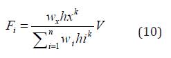
Where, Fx is the applied lateral force at level ‘x’, W is the storey weight, h is the storey height and V is the design base shear, and N is the number of stories distribution when k is set equal to unity. A uniform lateral load distribution consisting of forces, which is proportional to the storey masses at each storey level [7-10].
k = an exponent related to the structure period as follows:
For structures having a period of 0.5 sec or less, k = 1
For structures having a period of 2.5 sec or more, k = 2
Seismic map for the kingdom of Saudi Arabia
The Saudi Building Code (SBC-303-2007) gives seismic maps to the Kingdom of Saudi Building, as appeared in Figure 12-14. The summation in the denominator is helped through all storey levels. This resulted in a reversed triangular form.
Figure 12:Regions for Determination of the Maximum Considered Earthquake Ground Motion in the Kingdom of Saudi Arabia.

Figure 13:Maximum Considered Earthquake Ground Motion for the Kingdom of 0.2 SEC Spectral Response Acceleration (Ss in %g) (5 Percent of Critical Damping), Site Class B. (Region 6

Figure 14:Maximum Considered Earthquake Ground Motion for the Kingdom of 1 SEC Spectral Response Acceleration (S1 in %g) (5 Percent of Critical Damping), Site Class B. (Region 6).

Results of analysis of considered building due to gravity and earthquake loads
This part presents the results of the analysis and design of considered RC buildings according to earthquake loads. It also provides the staring actions of the building after adding seismic loads.
Straining action of some columns and beams due to gravity and earthquake loads
The moments in the columns and beams for the selected frames obtained from gravity and earthquake loads are shown in Table 8-11.
Table 8:The Straining action of some columns due to load case Group-X.

Table 9:Straining action of some beams due to load case Group-X.

Table 10:The Straining action of some due to load case Group-Y.

Table 11:Straining action of some beams due to load case Group-Y.

The straining action of some columns in the selected frames at direction X-Z @ Y = 1.5& Y = 11.5 due to load case group-X
Columns: Table 8 shows the straining action of some columns due to load case Group-X
Beams: Table 9 shows the straining action of some beams due to load case Group-X
The Straining action of some columns beams in the selected frames at direction Y-Z @ X = 1.5& Y = 19.5 due to load case group-Y
Columns: Table 10 Shows the Straining action of some due to load case Group-Y
Beams: Table 11 show the Straining action of some beams due to load case Group-Y
Modeling and Analysis of Existing RC Buildings due to Earthquake Loads after Strengthening
This part introduces the displaying and investigation of existing RC structures because of gravity and seismic tremor Loads subsequent to reinforcing.
Proposed strengthening method
There are distinctive strategies for seismic reinforcing of existing structures. Nonetheless, social and monetary conditions ought to be considered to pick the proper technique. Including auxiliary walls is a standout amongst the most widely recognized structurelevel retrofitting techniques to reinforce existing structures. This methodology is powerful to control worldwide parallel floats and for diminishing harm in edge individuals. Auxiliary walls might be either strengthened cement or steel plate.
Modeling of concrete shear walls
Figure 15:Modeling of the shear wall in direction XZ at Y=1.5.

The solid shear walls can be verified utilizing full shell components and isotropic material. The parallel power opposing framework comprises of minute opposing casings with solid shear walls. The considered building is broken down for gravity and seismic loads as recently clarified, i.e., utilizing the SAP2000 auxiliary investigation programming bundle. Fortified solid walls with thicknesses of 20cm have been decided for this contextual investigation. We chose two edges in bearing X and Y as appeared in Figure 15-18.
Figure 16:3D view of the shear wall in direction XZ at Y=1.5.

Figure 17:Modeling of the shear wall in direction YZ at X=1.5.

Figure 18:3D view of the shear wall in direction YZ at X=1.5.

Results of analysis of considered building due to gravity and earthquake loads after strengthening
Figure 19:Comparison between the moments at selected columns in the direction XZ @Y=1.5 due to combination load case (Group-X).

Figure 20:Comparison between the moments at selected columns in the direction XZ @Y=11.5 due to combination load case (Group-X).

This part introduces the consequences of examination and plan of considered RC structures because of gravity and seismic tremor stacks subsequent to reinforcing. It likewise gives the gazing activities of the working in the wake of including tremor loads and fortifying Figure 19-23.
Figure 21:Comparison between shear forces at the selected columns in the direction XZ @Y=1.5 due to combination load case (Group-X).

Figure 22:Comparison between bending moments at selected beams in the direction XZ @Y=1.5 due to combination load case (Group-X)

Figure 23:Comparison between bending moments at selected beams in the direction XZ @Y=11.5 due to combination load case (Group-X).

Straining activity of a few columns and bars because of gravity and seismic tremor stacks subsequent to reinforcing
Table 12:The minutes and pivotal forces on a few segments in the chose edges because of gravity and seismic loads in the wake of fortifying.

Table 13:The moments and axial forces on some beams in the selected frames due to gravity and seismic loads after strengthening.

Table 14:The moments and axial forces on some columns in the selected frames due to gravity and seismic loads after strengthening.

Table 15:The moments and axial forces on some beams in the selected frames due to gravity and seismic loads after strengthening.

The minutes in the segments and shafts for the chose edges acquired from gravity and quake stacks subsequent to fortifying are shown in Table 12-15.
The Straining activity of a few segments in the chose edges at heading X-Z @ Y = 1.5& Y = 11.5 because of load case group-X : Table 12 Shows the Straining activity of a few sections because of load case Group-X
The Straining action of some columns in the selected frames at direction X-Z @ Y = 1.5& Y = 11.5 due to load case group-Y
Results, Discussion and Comparisons between the Analysis Results of the Studied Building before and after Strengthening
This part is concentrating on the outcomes, exchange, and examinations between the investigation’s aftereffects of the contemplated working when reinforcing (Figure 24-26). Just bearing XZ was considered in order to explore the impact of seismic forces on it, while for different headings the technique is comparable. Table 16-23 models the consequences of chose bars and segments to speak to part of entire outcomes which are referenced previously.
Table 16:Comparison between bending moments at selected columns in the direction XZ @Y=1.5 due to combination load case (Group-X).

Table 17:Comparison between bending moments at selected columns in the direction XZ @Y=11.5 due to combination load case (Group-X).

Table 18:Comparison between shear forces at the selected columns in the direction XZ @Y=1.5 due to combination load case (Group-X).

Table 19:Comparison between shear forces at the selected columns in the direction XZ @Y=11.5 due to combination load case (Group-X).

Table 20:Comparison between bending moments at selected beams in the direction XZ @Y=1.5 due to combination load case (Group-X).

Table 21:Comparison between bending moments at selected beams in the direction XZ @Y=11.5 due to combination load case (Group-X).

Table 22:Comparison between shear forces at selected beams in the direction XZ @Y=1.5 due to combination load case (Group-X).

Table 23:Comparison between shear forces at selected beams in the direction XZ @Y=11.5 due to combination load case (Group-X).

Figure 24:Comparison between shear forces at the selected columns in the direction XZ @Y=11.5 due to combination load case (Group-X).

Figure 25:Comparison between shear forces at selected beams in the direction XZ @Y=1.5 due to combination load case (Group-X).

Figure 26:Comparison between shear forces at selected beams in the direction XZ @Y=11.5 due to combination load case (Group-X).

a. Bending moments at the selected columns
b. Shear forces at the selected columns
c. Bending moments at the selected beams
d. Shear forces at the selected beams
Conclusion
The present study represents an attempt to study the effect of seismic loads on existing RC building in ABHA city, KSA. The obtained results emphasize the following conclusions:
A. The current plan of structures in the ABHA city does not consider seismic tremor loads.
B. It can be seen that including RC shear divider brought about a decent impact in diminishing twisting minutes in the building segments.
C. It has been discovered that the present plan of structures in ABHA is dangerous for the present seismicity of ABHA zone.
D. A reinforcing method for existing RC structures has been verified that RC shear walls really speak to an entirely appropriate methodology to lessen the seismic weakness of existing RC structures.
The present investigation speaks to an endeavor to think about the impact of seismic loads on existing RC working in ABHA city, KSA. The got outcomes underline the accompanying ends.
References
- CSI SAP2000 V-14 (2010) Integrated finite element analysis and design of structures basic analysis reference manual. Berkeley, California, USA.
- Saudi Building Code SBC-301-2007 (2007) Loads and forces requirements. Saudi Building Code National Committee.
- Pampanin S (2006) Controversial aspects in seismic assessment and retrofit of structures in modern times: understanding and implementing lessons. Bulletin of the Newzealand Society for Earthquake Engineering 39(2).
- Rai DC (2005) IITK-GSDMA guidelines for seismic evaluation and strengthening of buildings. Indian Institute of Technology Kanpur, Gujarat State Disaster Mitigation Authority, India.
- Central Public Work Department & Indian Building Congress in Association with Indian Institute of Technology (2007) Handbook on Seismic retrofit of Buildings, Madras, India.
- From Ancient Heritage (2006) Bulletin of the New Zealand society for earthquake engineering 39(2).
- Sobaih M, Ismaeil M (2012) A proposed methodology for seismic evaluation and strengthening of existing school buildings in the Sudan. Proceedings of 15th WCEE, Lisbon, Portugal.
- Otani S (2003) Earthquake resistant design of reinforced concrete buildings. Journal of Advanced Concrete Technology 2(1): 3-24.
- IBC2012 (2012) International building code. International Code Council.
- Al-Haddad M, Siddiqi GH, Al-Zaid R, Arafah A, Necioglu A, et al. (1994) A basis for evaluation of seismic hazard and design criteria for Saudi Arabia. Earthquake Spectra 10(2): 231-258.
© 2019 Mohammed Ismaeil. This is an open access article distributed under the terms of the Creative Commons Attribution License , which permits unrestricted use, distribution, and build upon your work non-commercially.
Editor In Chief


.jpg)


Signup for Newsletter

Quick Links
 Editorial Board Registrations
 Submit your Article
 Refer a Friend
 Advertise With Us
Our Recent Edition

.jpg)


Top Editors


.jpg)


.bmp)
.jpg)
.png)
.jpg)


.jpg)


.png)

.png)


.png)


Financial Support

Sponsors

Latest e-Books

Latest Video

 a Creative Commons Attribution 4.0 International License. Based on a work at www.crimsonpublishers.com.
Best viewed in
a Creative Commons Attribution 4.0 International License. Based on a work at www.crimsonpublishers.com.
Best viewed in