- Submissions

Full Text
Advancements in Civil Engineering & Technology
Tensile Behavior of Single Cast-in Anchors in Plastic Hinge Zones
Jian Zhao* and Zhibin Lin
Department of Civil and Environmental Engineering, Univ of Wisconsin, USA
*Corresponding author: Jian Zhao, Associate Prof, Dept of Civil and Environmental Engineering, Univ of Wisconsin, Milwaukee, WI, USA
Submission: July 25, 2018;Published: September 11, 2018

ISSN: 2639-0574 Volume2 Issue2
Abstract
This paper presents two tests of ¾-in. diameter cast-in anchors embedded in the plastic hinge zone of reinforced concrete columns. Design codes, such as ACI 318-11, do not allow concrete anchors in concrete that could be substantially damaged during an earthquake unless special reinforcement is provided. Recent studies have concluded that key role of anchor reinforcement, in addition to carrying the forces from the anchors, is to protect concrete around the anchors from splitting, breaking out, and crushing. The anchor reinforcement in this study was designed according to the recommendation. The column specimens were subjected to quasi-static cyclic loading before the test anchors were loaded in tension. Ductile steel fracture was achieved in both test anchors despite cracks and concrete spalling occurred to the concrete within the plastic hinge zones.
CE Database Subject Headings Cast-in anchors; Anchor reinforcement; Concrete anchor; Studs; Fastening to concrete; Reinforced concrete; Embedded connections; Seismic design
Introduction
Cast-in concrete anchors and headed studs, embedded in concrete, are used to connect structural steel members and concrete. Typical embedded connections include brace-column connections and girder-wall connections. Such connections are a critical component in composite construction between steel and concrete members, affecting structural performance during earthquake events. For example, shake table tests of structure models have shown that the embedded connections are susceptible to damage in earthquakes, which in turn disturbs the desired structural performance [1,2]. Typical failure modes for cast-in anchors in tension are anchor steel failure and concrete breakout failure. Anchor steel failure is caused by fracture of an anchor shaft in tension while concrete breakout failure is marked by a concrete cone broken away from the base concrete, in which the connection is located. Concrete breakout failure occurs when anchors are located close to an edge or with a small embedment depth. Concrete breakout is a brittle failure mode and thus not preferred for anchor connections in seismic zones [3]. The well-established design procedures for concrete anchors, such as those stipulated in ACI 318-11, do not apply to the anchors installed in plastic hinge zones. This is because the concrete in plastic hinge zones likely develops substantial damaged during an earthquake while the design procedures are based on experimental tests of anchors in concrete that is not stressed/cracked.
Anchor reinforcement must be provided for the anchors installed in plastic hinge zones. The existing anchor reinforcement recommended in ACI 318-11 code, mainly U-shaped hairpins placed close to the anchor, may not be construction friendly. In addition, laboratory tests have indicated that the hairpins may be able to restrain concrete breakout failure; however, the desired anchor steel failure may not be achieved unless the concrete around the anchor is properly confined [4]. The tests of concrete anchors installed in highly damaged concrete is scarce. Therefore, engineers are left with no guidance when designing such embedded connections. A new method for designing anchor reinforcement has been proposed and verified using anchor tests in undamaged concrete. In this paper, laboratory tests were presented to evaluate the recommended reinforcement for anchors installed in the plastic hinge zone of concrete columns.
Literature on Anchor Behavior in Damaged Concrete
Modern design of concrete structures allows the development of plastic hinges at beam ends column bases in moderate or high seismic zones [5]. The concrete in plastic hinge zones is expected to experience extensive inelastic deformation, including concrete cracking and crushing. Meanwhile, the current building codes and design guidelines for concrete anchors are based on experimental tests of anchors installed in concrete that experiences controlled minor damage [6-8]; hence the existing design equations cannot be used for anchors in plastic hinge zones. A brief review of the studies of anchors in damaged/cracked concrete is provided below followed by a review of existing anchor reinforcement designs.
Studies of anchors in damaged concrete
Copley and Burdette [9] tested seven four-anchor connections, including three with A307 bolts, two self-drilling anchors, and two wedge anchors. The slabs with the anchor groups installed at mid-span were simply supported, and the support positions were designed to control the maximum moment (and therefore the maximum cracking) in the slabs at the designated loads. The tension loads applied to the anchor groups also deformed and cracked the slabs. The tests showed that almost all connections could resist the design loads though the levels of damage, including crack widths, were not reported. Eligehausen and Balogh [10] summarized a series of tests for various types of anchors installed in cracked concrete in Europe, including headed studs and cast-in anchors. For example, the tension tests of headed studs by Martin and Schwarzkopf [11] indicated that the reduction of the concrete breakout strength can be 30 percent when the studs are installed in cracked concrete. The crack width through the depth of the concrete slab was held constant at 0.46mm [0.018in.] during the tests. Similar capacity reduction was observed by Yoon et al. [12] with twelve tension tests of headed studs in pre-cracked concrete with a crack width up to 0.51mm [0.02in.]. Tests have also been conducted by Jang and Suh [13] to provide experimental data for anchors in cracked concrete. The study was to verify the codespecified capacity reduction factors for anchors in cracked concrete. The test variables included crack width (up to 1.5mm [0.059in.]); crack depth (up to 102mm [4.0in.]); crack position (intersecting the anchors and 76mm [3in.] from the anchors); and the number of cracks (one and two cracks). The measured concrete breakout capacities were found not affected by the intersecting cracks while the specimens with cracks away from the test anchors showed 35% capacity reductions.
The preformed cracks used in the above studies do not represent well the concrete condition in the plastic hinge zones. An analysis performed by Hoehler [14] indicates that a crack around 1.0mm [0.04 in.] wide is likely the maximum crack experienced by reinforced concrete flexural members outside the plastic hinge zones. As a part of the study, Hoehler [14] also conducted tests to investigate the impact of crack opening-closing caused by seismic action on concrete members. The resultant crack movement test has been specified as an acceptance test for post-installed anchors [15].
Shahrooz et al. [16] tested a wall specimen with two anchor connections: one close to the base and embedded in the densely reinforced boundary element, and the other located higher and outside the densely reinforced region. The specimens were designed to simulate the connections between outrigger beams and reinforced concrete core walls in a high-rise building. The wall specimens were subjected to an axial compressive force equivalent to 10 percent of their axial capacities followed by reversed cyclic displacements at the top of the wall. In the meantime, each of the two anchor connections was subjected to 50% of the measured shear force. Concrete crushing and cracking occurred below the bottom test connection. The bottom connection developed ductile behavior despite the damage in concrete because the connection is protected by the reinforcing cage in the boundary element. Meanwhile, the top connection failed by concrete breakout though the concrete around the connection developed little damage.
Anchor reinforcement design
Building codes and design guidelines allow engineers to use steel reinforcement to avoid concrete breakout failure in design [5]. The existing design methods for anchor tension reinforcement are summarized in Figure 1. The recommended anchor reinforcement usually consists of U-shaped hairpins, placed close to the anchor. Concrete breakout is assumed to form before the hairpins within a certain range from the anchor becomes efficient in carrying the tensile force. The load transfer from the anchor bolt to nearby reinforcement has been modelled as that between spliced deformed bars [17] or visualized using strut-and-tie models (STMs) [18]. The U-shaped hairpins are required to be within a distance equal to half of the embedment depth (0.5hef) as illustrated in Figure 1. This effective range is increased in CEN/TS (2009) to 0.75hef. In addition, stirrups in beams within 1.0hef from the anchors can be counted as reinforcement for anchors according to a CEB report [19].
Figure 1:Existing reinforcement schemes for anchors in tension.

Petersen et al. [4] evaluated the behavior of cast-in anchors with code-complying anchor reinforcement using experimental tests. Compared with the anchors embedded in plain concrete, a capacity increase ranging from 20% to 130% was observed in the tests of the anchors with anchor reinforcement. However, the expected steel fracture was not achieved mainly due to the lack of confining reinforcement. Splitting cracks developed passing through the anchors in all tests. The concrete around the anchor head lost its confinement, and crushed prematurely, resulting in anchor pullout failure. Based on these observations and other tests in the literature, recommendations for anchor tension reinforcement have been proposed [4]. The proposed reinforcement, as illustrated in Figure 2 includes: 1) load-carrying reinforcement in the direction of the anchors; 2) crack-controlling reinforcement in all directions that have a limited edge distance; and 3) local confining reinforcement near the anchor head if side-face blowout may control the failure. In addition, the tensile load on the anchors eventually needs to be transferred to the rest of the structure. Enough reinforcement, such as stirrups and surface bars, is needed to ensure proper load transfer.
Figure 2:Proposed anchor tension reinforcement (1 in.=25.4mm).

The load-carrying reinforcement was suggested to be proportioned to carry a force equal to the design tensile capacity of the anchor. The nominal yield strength of steel should be used in the calculation. The load-carrying reinforcement should be implemented using small-diameter closed stirrups. The stirrup dimension should be small yet satisfy the bending radius requirements such that the load-carrying reinforcement can be close to the anchor. The depth of the stirrups should be large enough such that the vertical legs are fully developed for the tensile load at both sides of the anchor head. Two stirrups should be placed next to the anchor shaft, where the crack in concrete may initiate above the anchor head under a tensile load. Rather than placing all bars within a small distance from the anchor, closely spaced stirrups with a center-on-center spacing of 51 to 76mm [2 to 3 in.] can extend 1.0hef, where hef is the embedment depth of the anchor, from the anchor bolt, as shown in Figure 2. Although the development length requirements for the anchor reinforcement can be satisfied through the interaction between the closed stirrups and corner bars, it was recommended that the closed stirrups are at least 8.0db from the anchor head, where db is the stirrup diameter.
Petersen et al. [4] stressed the necessity of crack-controlling reinforcement crossing all possible splitting cracks. Considering the load transfer from the anchor head to the load-carrying reinforcement: a strut-and-tie model can be established with the struts conservatively assumed from the anchor head to the outmost load-carrying stirrups. The rest of the crack-controlling reinforcement can be determined considering the load transfer from the load-carrying reinforcement to the rest of the structure. All crack-controlling reinforcement was suggested to be proportioned using a stress of 0.6fy, , and implemented using small diameter bars evenly distributed with a small and practical spacing in two orthogonal directions. The above recommended anchor reinforcement has been verified using the tensile tests of anchors embedded in undamaged concrete. This paper presents the tests of anchors with the recommended anchor reinforcement in significantly damaged concrete. A total of three reinforced concrete (RC) columns were used for the single anchors in plastic hinge zones, and the results of two tests are discussed as follows.
Experimental Program
Reinforced concrete column specimen
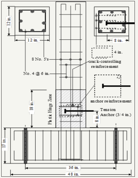
The RC columns had a section of 305×305mm [12×12 in.] and a height of 1.55m [5.1ft.] from the top face of the base block, as shown in Figure 3. The column base block had a dimension of 1219×508mm [48×20 in] and a height of 432mm [17 in.] Two tiedown holes were created using embedded PVC tubes. The tie down points were 0.91m [3ft.] from the center of the column, following the hole pattern in the strong floor of the UWM Structures Laboratory. The horizontal loads were applied to the top of the column at 1.57m [62 in.] from the base through a steel loading block. Eight No. 5 bars (ASTM Grade 60) were provided as the longitudinal reinforcement for the columns. The concrete cover was 38mm [1.5in.], typical for RC members with exterior exposure. A section analysis with the actual material properties shown below indicated that the column had a nominal moment capacity about 105.8kN-m [78 k-ft.]. This corresponded to a lateral load capacity about 67.4kN [15 kips] at the top of the column. A shear design calculation for this ultimate load led to No. 4 ties at a spacing of 152mm [6 in.], as illustrated in Figure 3.
Figure 3:Dimension and reinforcement of tension sepcimens (1 in.=25.4mm).
Test anchors
The test anchors were made from 19-mm [¾-in.] diameter ASTM A193 Grade B7 threaded rods. The net tensile area (Asa,N)) for the threaded rods was 2.2cm2 [0.334 in.2]. The test anchors thus can have an ultimate tensile capacity (Nu) of 196kN [44 kips]. A 6.4-mm [¼-in.] thick steel plate washer (38×38mm [1.5×1.5 in.]) and a hex nut were tack welded to the end. The required net bearing area (Abrg) for the plate washer was determined assuming the anchor pullout capacity (8.0fc’Abrg, where fc’ is the specified concrete strength, 27.6 MPa [4000 psi]) would be higher than the ultimate tensile load corresponding to anchor steel fracture. Note that pullout failure would have controlled the anchor behavior if the concrete around the anchor head were not well confined. The test anchor had an embedded length (hef) of 203mm [8 in.]. With the provided anchor reinforcement, concrete breakout failure was not expected; nevertheless, the concrete breakout capacity of the test anchor was calculated as 54.7kN [12.3 kips] using the equation in Section D5.2 of ACI 318-11. Note that a complete breakout cone was unlikely to form as the flexural cracks in the column might provide shortcuts for the propagation of breakout cracks.
The test anchor was installed 203mm [8 in.] above the base block. The length of the plastic hinge zone was assumed as 0.46m [18 in.] (that is 1.5 times the column section height), as shown by shaded region in Figure 3. The anchor position was selected assuming a crack spacing of 51mm [2 in.] such that a major flexural crack would pass through the test anchor if the anchor reinforcement were not provided. The design of the anchor tension reinforcement using strut-and-tie models is illustrated in Figure 4. The required anchor reinforcement for the 19-mm [¾-in.] anchors in tension was found to be 4.7cm2 [0.73 in.2], following the design method shown in the previous section. Two No. 4 ties (with four stirrups legs parallel to the anchor as the load-carrying reinforcement) were provided: one located 51mm [2 in.] above the test anchor and the other below the anchor, as shown in Figure 3. The stirrup legs, used as the load carrying reinforcement, were located about 127mm [5 in.] (0.6hef) from the test anchor, within the above recommended effective range (1.0hef); however, breakout cracks were expected because the load-carrying bars were not placed next to the test anchor as recommended by Petersen et al. [4] due to space limitation.
Figure 4:Strut-and-Tie models for the specimen design (1 in.=25.4mm).
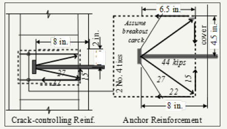
Figure 5:Surface cracks near test anchor in the plastic hinge zone.
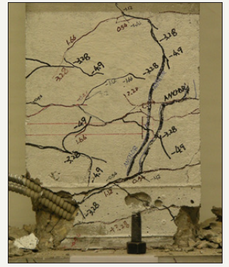
Crack-controlling reinforcement is important for the load carrying reinforcement to function. With the configuration shown in Figure 4, the horizontal splitting force, which might cause vertical splitting cracks, was calculated as about 66.7kN [15 kips]. The two No. 4 ties (the load-carrying reinforcement) and two adjacent ties provided enough crack-controlling reinforcement, as illustrated in Figure 3. In addition, the column was expected to develop flexural cracks under lateral loading, especially in the plastic hinge zones. The cracks could propagate passing the test anchor, in which case the concrete bearing strength can be significantly reduced. This cracking potential is in addition to that caused by the tensile force on the test anchor, as shown in Figure 4. Different from the tests in Pertersen et al. [4], where the longitudinal bars in the concrete beam were used to restrain splitting cracks, local crack-controlling reinforcement must be used in this study. Three No. 4 U-shaped hairpins were placed in the vertical plane for this purpose, encasing the two No. 4 ties, as shown in Figure 3. The tensile force on these crack-controlling bars was calculated as about 66.7kN [15 kips] using the strut-and-tie model in Figure 4 and required roughly two No. 4 hairpins. One additional hairpin was placed in the middle to restrain the flexural cracking near the anchor heads. The development length requirement for both the No. 4 ties and the U-shaped hairpins was assumed satisfied through the interaction between the closed ties and corner bars. Assuming a 35-degree breakout crack (Figure 4), the legs of two No. 4 ties (used as loadcarrying reinforcement) had a development length about 102mm [4 in.] at both side of the cracks, close to recommended by Petersen et al. [4]. The breakout cracks did not actually propagate in a 35-degree angle, as shown later in Figure 5; nevertheless, the closed ties performed well through the interaction with corner bars.
Materials
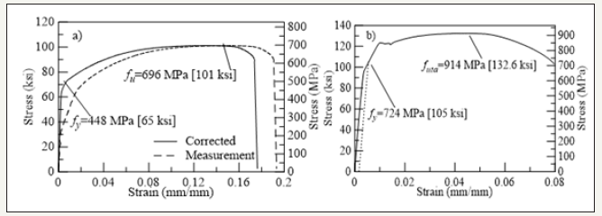
Ready mixed concrete with Wisconsin Department of Transportation Type A-FA mixture was used. The specified concrete compressive strength was 27.6 MPa [4000 psi]. The hardened concrete had a compressive strength of 40 MPa [5800 psi] at 28 days, and the compressive strength went up to 47.6 MPa [6900 psi] at about 84 days, when the tests presented in this paper were conducted. Eight No. 5 reinforcing steel bars with a nominal yield strength of 414 MPa [60ksi] were used as longitudinal reinforcement. The measured stress-strain relationship, shown in dashed lines in Figure 6 experienced a grip slip. A correction was performed based on the strain gage readings and the strains calculated from the measured elongation over a 203-mm [8- in.] gage length. The corrected stress-strain relationship, shown in solid lines in Figure 6, indicates a yield strength of 448 MPa [65ksi] using the 0.2% offset method. The ultimate strength of the reinforcing bars was measured 696 MPa [101ksi] at a strain about 0.15. The stress-strain relationship of ASTM A193 Grade B7 rods was measured using the tensile test of a coupon made from a rod. Again, a grip slip was observed when the stress was above 620 MPa [90ksi], as shown in Figure 6. No strain gage was used in this test; hence a correction was not performed. The measured yield strength was 724 MPa [105ksi] corresponding to a 0.2 percent residual strain. The measured ultimate strength was 914 MPa [132ksi] at a strain about 0.045.
Figure 6:Materials used in test: a) No. 5 Grade 60 rebars; b) ASTM A193 Grade B7 rods.
Test setup and loading protocol
Figure 7:Test setup for tension tests of cast-in anchors in plastic hinge zone
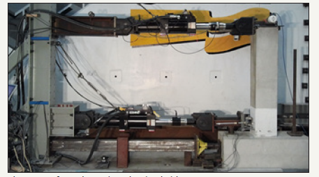
The test setup is shown in Figure 7. The column specimen was fixed to the strong floor of the laboratory using two high-strength threaded rods. An MTS Model 244.31, 245-kN [55-kip] actuator was used to apply a reversed cyclic displacement at the top of the column. The lateral load was applied to the column at 1.58m [62 in.] above the base block. Another MTS Model 244.31 actuator was used to apply tensile forces to the anchor. The centerline of this actuator was located at the height of the test anchor. Strain gages and linear potentiometers were used to monitor the behavior of the test columns and the anchors. The instrumentation details can be found elsewhere [4]. The columns were subjected to reversed cyclic displacements. The displacement history included groups of three cycles with the peak displacements corresponding to ±0.5y, ±y, ±2y, ±3y, ±4y, ±6y, and ±8y. The yield displacement (Dy) was determined prior to the tests using a fiber-based analysis of the column. The loading rate for displacement cycles were kept at 6mm/min [0.24 in./min] throughout the tests.
The anchor in Specimen T2 was loaded (in displacement control) in monotonic tension untill failure after the column was subjected to the predefined loading history described above. The anchor in Specimen T3, on the other hand was loaded in cyclic tension, and the actuator was in load control. Based on the measured load-displacement relationship of Specimen T2, the peak tensile loads were selected as 93, 186, 191, and 196kN [21, 42, 43, and 44 kips], and three loading cycles were used for each peak load. The anchor was then loaded monotonically to failure after these loading cycles. The loading rate was kept 5.3kN/min [1.2 kips/ min]. The load-controlled loading protocol was used instead of a displacement-controlled protocol because of the hydraulic control complication: the column top was supported by the top actuator (Figure 7), which was controlled to maintain a zero displacement when the cyclic tensile loads were applied to the test anchor. When a displacement-controlled loading was first used, a large reaction force was sensed by the top actuator, which triggered its interlock, and stopped the test unexpectedly.
The test specimen could fail in several possible failure modes under the complex combination of column loading and anchor loading. Design checks for the column were conducted for a variety of failure modes to ensure that column specimen would not fail before the testing anchor reached at its full design capacity. These failure modes included flexural and shear failure of the column under the load from the test anchors. In addition, shear friction along flexural cracks was found unlikely to control the failure of the test. Details about the design checks can be found elsewhere [20] while similar design calculations are recommended for design practices.
Discussion of Test Results
Column surface cracks
Figure 8:Crack map of Specimen T2 column at 8y (Crack width in mm; 1 in.=25.4mm).
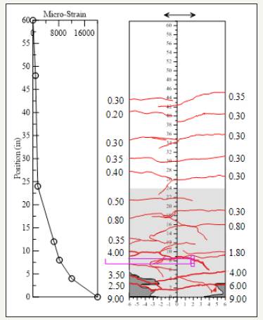
The columns had a typical hysteretic behavior found in flexural members. An examination of the strains in the middle longitudinal bar indicated that the first yield occurred during the loading cycle at about 13mm [0.5 in.]. The largest column displacement was about 102mm [4 in.], corresponding to 8y at a peak load about 67kN [15 kips]. The crack map of Column T2 is shown in Figure 8 after all column loading cycles were completed. The crack development is described briefly as follows: a flexural crack at the base was first observed along with a crack at 203mm [8 in.] above the base during the ±y loading cycle. Note that the column base crack is a result of yield penetration of steel reinforcing bars in the foundation. The crack width at the base of the columns was 0.3-0.5mm [0.01-0.02 in.] at first yielding, which is close to the bar yield slip predicted by Zhao and Sritharan [21]. More cracks developed throughout the column during the following loading cycles. The crack widths in Figure 8 were recorded after the ±8y loading cycles. The largest crack at the column base was 9.0mm [0.35 in.], which is slightly less than the ultimate bar slip recommended by Zhao and Sritharan [21]. The strains in the longitudinal bar are shown in Figure 8 at the first peak of the ±8y loading cycles, when the crack widths in Figure 8 were recorded. The plastic hinge zone, shown in the shaded zone, was 610mm [24 in.] high, which is roughly twice the column section height. The largest crack width was 0.4mm [0.06 in.] outside this region. This observation confirms the that the design equations in Appendix D of ACI 318-11, which are established based on tests of anchors largely in undamaged concrete, can be used outside the plastic hinge zones, defined as twice the member depth from a column or beam face.
Anchor behavior in tension
Monotonic behavior in Specimen T2: The load vs. displacement behavior of the anchor in Specimens T2 and T3, as plotted in Figure 9 demonstrates that the anchor ductile failure was achieved. Concrete within the plastic hinge zone developed extensive cracks before the anchor was subjected to tensile loading, as illustrated in Figure 10. However, the core concrete was well confined by the provided anchor reinforcement, including the crack-controlling reinforcement. The yield load of the anchor was 156kN [35 kips] as calculated by the production of the measured yield strength (fyta) and the net tensile area of the anchor (Asa,N)). At the corresponding stress (621MPa [105ksi]), the strain in the anchor steel is 0.0058 mm/mm from the measured stress-strain relationship in Figure 6, and the elongation of the 203mm [8-in.] long anchor is about 1.2mm [0.046 in.]. This elongation is very close to the yield displacement measured relative to the concrete surface (about 1.3mm [0.05 in.]), as shown in Figure 9. The measured tensile capacity is about 200kN [45 kips], slightly larger than the predicted capacity using the measured ultimate strength of anchor steel. At the peak load, the measured anchor displacement is 7.6mm [0.3 in.], less than the production of the ultimate strain (0.045mm/ mm) and the embedded length (203mm [8 in.]). This is reasonable because the ultimate strain only occurred to a small length of the anchor shaft near the fracture point [22,23].
Figure 9:Behavior of single anchor in plastic hinge zone under tensile loading.
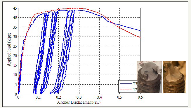
Cyclic behavior in Specimen T3: The anchor bolt in Specimen T3 was subjected to cyclic loading. The peak loads were selected based on the results of T2 test to spread the cyclic loading throughout the entire range of the static behavior. One thing in the test of Specimen T3 that was different from the test of Specimen T2 is that before the final loading to failure was applied to the test anchor, the column was deformed to in the negative direction. The reason for trying this different configuration was that the cracks in the plastic hinge zone would open wide in this case, creating likely the worst situation for the test anchor. The cyclic load vs. displacement curve of Specimen T3 closely followed the monotonic path throughout the entire loading range, as shown in Figure 9. The anchor behaved elastically during the 22-kip loading cycles, and the cyclic loading did not cause degradation in the anchor behavior as the anchor peak displacements did not increase in the consecutive loading cycles. Such degradation is also small at the larger-load cycles, indicating a reliable anchor behavior [24,25].
The anchor bolt, after the cyclic loading, was able to carry a tensile load of 196kN [44kips], which is slightly smaller than the monotonic capacity of Specimen T2. The small difference may have been caused by upward rotation of the anchor when the column was deformed to 8Δy. The small anchor rotation may have caused a small bending in the anchor shaft when the anchor was loaded in tension. This hypothesis is partially supported by the anchor fracture surfaces: the left picture inserted in Figure 9 shows cupand- cone shaped failure surface for Specimen T2 while the right picture for Specimen T3 shows a slightly different failure surface.
Behavior of confined core: Concrete within the plastic hinge zones was extensively cracked as shown in Figure 5 before the anchor was subjected to tensile loading. Specifically, a major crack with an opening of 4.0mm [0.16 in.] can be observed near the test anchor, as shown in Figure 8. This flexural crack might have impacted the tensile behavior of the anchor if no crack-controlling were used. The large surface crack did not extend through the core concrete around the anchor head as shown in Figure 10, largely because of the U-shaped hairpins used as the local crackcontrolling reinforcement. Well-confined core concrete ensured the load transfer from the anchor bolts to the rest of concrete. Concrete breakout cracks formed due to a limited side edge distance, as shown by the vertical crack near the anchor head marked by “ANCHOR” in Figure 5. The breakout cracks on the side faces are at the same location as the anchor head, indicating that a 35-degree crack propagation assumed in Figure 4 did not occur. In addition, the breakout cracks on the side faces were observed at a load about 187kN [42kips], instead of the calculated concrete breakout capacity (67kN [15kips]). The breakout crack below the anchor propagated from the anchor head in an angle because of the reaction provided by the base block. The crack was soon arrested by a flexural crack in the column outside the locally confined core. The breakout crack above the anchor did not propagate in a similar angle because the top support was located far from the test anchor.
Figure 10:Well-confined core concrete in the plastic hinge zone.
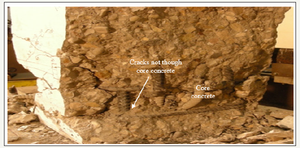
The 4-mm [0.16-in.] flexural crack at 51mm [2 in.] above the base block, which was likely through the entire column section, was the weakest link in the loading resisting system. The column slid along this flexural crack before the anchor fracture as revealed by the concrete powder found along the crack in Figure 10. The shear friction failure did not control the test because of the high shearfriction capacity. This observed anchor fracture failure was possible because the concrete near the anchor head was well confined by the provided anchor reinforcement, including the local crackcontrolling bars that prevented cracks from passing through the anchor bolt. The single-anchor specimens embedded in the plastic hinge zone of columns developed ductile steel fracture despite large cracks and concrete spalling occurred to the concrete. The successful tests indicated that well confined core concrete, even within plastic hinge zones, can support anchor connections in tension. Suitable anchor reinforcement must be provided. Meanwhile, it should be noted that further tests are needed including the tests of anchor groups and moment connections in plastic hinge zones before practical applications.
Conclusion
This paper presents two tests of cast-in anchors installed in the plastic hinge zone of concrete column specimens. Appendix D of ACI 318-11 requires special reinforcement if anchors must be installed in plastic hinge zones. The anchor reinforcement was provided to the anchors in this study following the recent recommendations in the literature. The recommended anchor reinforcement emphasizes the importance of confining concrete and restraining concrete from cracking in addition to distributing loads from the anchor to the rest of the structure/structural element. The single-anchor specimens embedded in the plastic hinge zone of columns developed ductile steel fracture despite large cracks and concrete spalling occurred to the concrete.
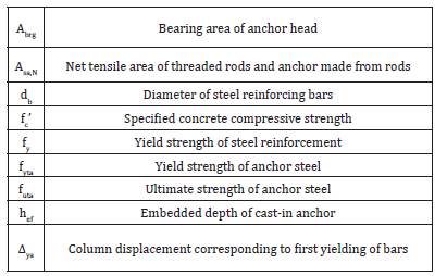
AppendixThe following symbols are used in this paper.
Acknowledgment
The study reported in this paper is from a project funded by the National Science Foundation (NSF) of the United States under Grant No. 0724097. The authors gratefully acknowledge the support of Dr. Joy Pauschke, who served as the program director for this grant. Any opinions, findings, and recommendations or conclusions expressed in this paper are those of the authors, and do not necessarily reflect the views of NSF.
References
- Gong Z, Lu X, Lu W, Li P, Yang S, et al. (2004) Shaking table model test of a hybrid high-rise building structure. Earthquake Engineering and Engineering Vibration 24(4): 99-105.
- Zhou Y, Yu J, Lu X, Lu W (2012) Shaking table model test of a highrise hybrid structure building with steel frame-concrete core wall. Earthquake Engineering and Engineering Vibration 32(2): 98-105.
- Petersen D, Lin Z, Zhao J (2013a) Reinforcement for Headed Anchors. Final Report for Project-Behavior and Design of Cast-in-Place Anchors under Simulated Seismic Loading. Volume 1, University of Wisconsin, Milwaukee, Wisconsin, USA.
- Petersen D, Lin Z, Zhao J (2018) Design of anchor reinforcement for seismic tension loads. Engineering Structures 164(6): 109-118.
- American Concrete Institute (ACI) Committee 318 (2011) Building code requirements for structural concrete (ACI 318-11). Farmington Hills, Michigan, USA.
- Eligehausen R, Mallée R, Silva J (2006) Anchorage in concrete construction. Wilhelm Ernst & Sohn, Berlin, Germany.
- Pallarés L, Hajjar J (2010a) Headed steel stud anchors in composite structures, Part I: Shear. Journal of Constructional Steel Research 66(2): 198-212.
- Pallarés L, Hajjar J (2010b) Headed steel stud anchors in composite structures, Part II: Tension, Journal of Constructional Steel Research 66(2): 213-228.
- Copley JD, Burdette EG (1985) Behavior of steel-to-concrete anchorage in high moment regions. ACI Journal, Proceedings, 82(2): 180-187.
- Eligehausen R, Balogh T (1995) Behavior of fasteners loaded in tension in cracked reinforced concrete. ACI Structural Journal 92(3): 29-35.
- Martin H, Schwarzkopf M (1984) Versuche mit Kopfbolzen im gerissenen Beton (Tests with Headed Studs in Cracked Concrete). Institut fur Betonstahl und Stahlbeton, Report no. 578/84, Munchen, Germany.
- Yoon Y, Kim H, Kim S (2001) Assessment of Fracture behavior for CIP anchors fastened to cracked and uncracked concrete. KCI structural Journal 13(3): 33-41.
- Jang J, Suh Y (2006) The experimental investigation of a crack’s influence on the concrete breakout strength of a cast-in-place anchor. Nuclear Engineering and Design 236(9): 948-953.
- Hoehler M (2006) Behavior and testing of fastenings to concrete for use in seismic applications. PhD dissertation, Universität Stuttgart, Stuttgart, Germany, p. 261.
- American Concrete Institute (ACI) Committee 355 (2007) Qualification of post-installed mechanical anchors in concrete and commentary (ACI 355.2-07). Farmington Hills, Michigan, USA.
- Shahrooz B, Tunc G, Deason J (2004) Outrigger beam-wall connections. ii: subassembly testing and further modeling enhancements. Journal of Structural Engineering 130(2): 262-270.
- Hasselwander G, Jirsa J, Breen J, Lo K (1974) Strength and behavior of anchor bolts embedded near edges of concrete piers. Research Report 29-2F, Center for Transportation Research, the University of Texas at Austin, Texas, USA.
- Widianto Owen J, Patel C (2010) Design of Anchor Reinforcement in Concrete Pedestals. Proceedings of the 2010 Structures Congress, Orlando, Florida, USA, pp. 2500-2511.
- Comité Euro-International du Béton (CEB) (1997) Fastenings to concrete and masonry structures: state of the art report. Thomas Telford Service Ltd, London.
- Zhao J (2014) Seismic behavior of single anchors in plastic hinge zones of RC columns. Tenth U.S. National Conference on Earthquake Engineering Frontiers of Earthquake Engineering, Anchorage, Alaska, USA.
- Zhao J, Sritharan S (2007) Modeling of strain penetration effects in fiberbased analysis of reinforced concrete structures. ACI Structural Journal 104(2): 1-7.
- European Committee for Standardization (2009) Design of fastenings for use in concrete-Part 4-2: headed fasteners. CEN/TS 1992-4-2, Brussels, Belgium.
- Ibarra LF, Krawinkler H (2005) Global collapse of frame structures under seismic excitations. Report No. TB 152, The John a Blume Earthquake Engineering Center, Stanford University, Stanford, California, USA.
- Lin Z, Luke B, Shahrooz B, Zhao J (2013) Headed anchors in plastic hinge zone of reinforced concrete members. Final Report for Project - Behavior and Design of Cast-in-Place Anchors under Simulated Seismic Loading. Volume 3, University of Wisconsin, Milwaukee, Wisconsin, USA.
- Zhao J, Lin Z (2017) Design of anchor reinforcement for seismic tension loads. Engineering Structures.
© 2018 Jian Zhao. This is an open access article distributed under the terms of the Creative Commons Attribution License , which permits unrestricted use, distribution, and build upon your work non-commercially.
 a Creative Commons Attribution 4.0 International License. Based on a work at www.crimsonpublishers.com.
Best viewed in


.jpg)


 Editorial Board Registrations
 Submit your Article
 Refer a Friend
 Advertise With Us
.jpg)


.jpg)


.bmp)
.jpg)
.png)
.jpg)


.jpg)


.png)

.png)


.png)


