- Submissions

Full Text
Advancements in Civil Engineering & Technology
The Influence of Concrete Roads on Safety and Energy Saving in Tunnels
Stefan Krispel, Gerald Maier* and Martin Peyerl
Smart Minerals GmbH (SMG), Austria
*Corresponding author: Gerald Maier, Smart Minerals GmbH (SMG), Austria
Submission: April 27, 2018;Published: May 18, 2018

ISSN 2639-0574Volume1 Issue2
Abstract
Tunnels and underpasses are indispensable for the infrastructure and represent significant structures for the individual road traffic and the economy. An appropriate illumination of the traffic area (e.g. road surface and tunnel wall) is the most efficient contribution, not only to the safety, but also to the running costs of the tunnel. Brightness and light distribution in tunnels are not only influenced by the type and the performance of lighting, but also to a large extent by the optical properties of the road surface and the tunnel walls (i.g. brightness, reflectivity and degree of contamination). Therefore an appropriate choice of the building materials in terms of their optical properties is, beside the traditional material characteristics, essential. The goal of the research project was the examination of the effect of different materials for the road surface (e.g. concrete, asphalt) and the tunnel walls (e.g. different tunnel coatings) considering different levels of surface soiling on the lighting quality and the energy consumption of tunnel constructions. For realistic values of the lighting coefficients different and currently used tunnel constructions were examined. Three soiled tunnel constructions of different ages were chosen and their photometrical characteristics were determined before and after the tunnel cleaning. Using concrete pavement in tunnels leads to better illumination of the road surface as well as the tunnel walls. The good photometrical characteristics of concrete, especially when using the additive titanium oxide, results in an increase in brightness of the road-surface and the tunnel walls. This improves the individual sense of security and decreases the energy input for lighting.
Keywords: Concrete roads; Pavement; Tunnel safety; Energy-saving; Illumination; Brightness; Shotcrete; Company Junger; Broll
Introduction
Especially in mountain areas, tunnels and underpasses are indispensable for the infrastructure and represent significant structures for the road traffic. Besides the benefits, such as reduction in transport time and distance, tunnels also pose high safety technologic requirements to the road maintainers resp. tunnel operators. An according illumination of the traffic area is the most efficient contribution with regard to the safety of the individual as well as to the running costs of the tunnel. Brightness and light distribution in tunnels are not only influenced by the type resp. the performance of lighting, but to a large extent also by the optical surface properties of the road and the tunnel walls such as i.e. brightness, reflectivity and degree of contamination. The according choice of construction material with regard to its surface luminosity and its reflectivity is therefore paramount.
That is why the goal of the research project was the investigation of the influence of different materials for roads (tarmac, concrete surface, brightened concrete surface) and tunnel walls (tunnel coating with various degrees of contamination, grey and white shotcrete) on the lighting quality and the energy consumption of tunnel constructions. In order to achieve comparable results, the investigation was conducted under stable conditions in an existing test tunnel. These way tunnel specific parameters, such as i.e. geometry and illumination arrangements, can be ruled out. Additionally the effects of the ideal surface choice are also presented visually. Doing so, planners of future tunnel constructions shall be enabled to create an improved lighting situation in tunnels and underpasses and therefore to contribute to strengthening the subjective sense of security for the individual road user.
Materials and Methods
Project implementation
In order to simulate various degrees of contamination of tunnel walls, the reading of the lightness coefficients were conducted in different and currently active tunnel constructions. For this purpose three contaminated tunnel constructions of different ages were chosen and their photometrical characteristics were determined before and after the tunnel cleaning. The observation took place at 5 representative locations with 10 individual recordings each. Figure 1 exemplarily shows the determination of lightness coefficients of a contaminated tunnel surface using a spectrophotometer.
figure 1:Recording of lightness coefficients at 5 different locations before and after tunnel cleaning.

Based on the identified luminosity characteristics the mapping of the determined lightness coefficients resp. of the key photometric values of coatings with similar photometric properties took place in a colour laboratory. As a result it was possible to simulate various degrees of contamination (sign-off conditions, lightly contaminated, heavily contaminated, cleaned) by colouring the inner shell of the test tunnel. Additionally alternative inner shell coatings with grey and white spray mortar were used.
Test conditions and metrological detection
figure 2:Original test tunnel. [Source: VÖZFI].
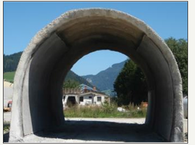
figure 3:depicts typical examples of tunnel coatings with different contaminations as well as white shotcrete application.
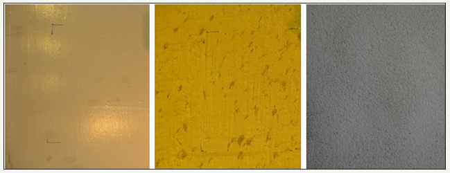
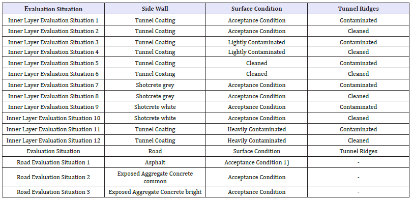
Table 1:Various Evaluation Situations.
Asphalt was sandblasted in order to simulate the surface conditions after approx. 1 year of usage (slight brightening by wearing down the bitumen to aggregate of the road surface).
Figure 2 shows a test tunnel with a diameter of approx.6m and a length of approx.20m in its original condition. After the adaptation of the tunnel its inner surface could be coated with different surface systems. (Figure 3) Tarmac, conventional road surface in exposed aggregate concrete and especially bright washed concrete were chosen as road surfaces. The combination of different roads, tunnel paint systems and of contamination degrees (clean/dirty) adds up to 36 different evaluation situations (Table 1).
The evaluation of the specific conditions took place with three types of lamps, which are used in road building factories: metal halide lamps (HQI-lamps), sodium vapour lamps (NVA-lamps) and light emitting diode lamps (LED-lamps). The lamps, that had different dimensions, were placed in the middle of the test tunnel and could be moved in a manner that allowed a fixation at exactly the same position (height and location). A luminance camera was put up in 60m distance of the lamp at a height of 1,5m in order to measure the light density of the road surface. This first calibration measurement took place during night-time. The following measurements then took place in darkened portals, also in a smaller distance of the tunnel lamp in the tunnel itself.
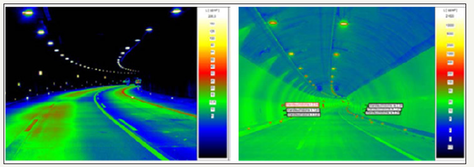
Another important implication was the consideration of the luminance of the wall. Currently some European guidelines consider the ratio of „luminance road“to „luminance wall“. Doing so can, for example, decrease the illumination level during a higher luminance of the wall [1,2]. The Austrian guidelines do not mention specific suggestions for this situation, but the research results could point out the impact of the used tunnel materials (walls, roof and road) on the necessary interior lighting [3]. The control of the different type of lamps took place using a specially adapted control cabinet that allowed dimming of the various lighting fixtures in a manner that guaranteed a constant similar light density at a previously defined spot. Additionally the control cabinet pointed out the used energy in the dimmed situation. The light density sensor of the company Electric Special that was used offers the possibility to compare various light densities (i.e. tunnel wall and road) with each other and to statistically analyse them. As an example, Figure 4 illustrates the light density distribution of tunnel constructions with different surface conditions of the tunnel walls. The exact same surface geometry allows the direct comparison of all results and hence well-founded statements about the surface characteristics and their impact.
figure 4:Illumination example with very low (left) and very high luminance values (right) on the wall. (Source: Broll Lighting Systems).
Construction of the concrete road surface
figure:5 Construction of concrete surface for the test tunnel.

The concrete road surface for the test tunnel should be exchangeable and portable, in order to have the possibility to change the road-surface during the test of different evaluation situations. The concrete surface was constructed as top-layer exposed aggregate concrete according to requirements of RVS 08.17.02 [4]. Additionally to the conventional concrete road (MV101-Exposed Aggregate Concrete common) a concrete road with brightening titanium oxide colour pigments was built (MV102- Exposed Aggregate Concrete bright). The road was made in an auxiliary formwork on XPS boards (2cm) with thickness of 8cm. The surface of the road to be built was approx. 45m². Subsequently the cement paste was brushed off and the concrete road was cut into 72 panels, sized 80x130cm that were individually stored on pallets (80x130cm) (Figure 5).
a. Prepared auxiliary formwork 3,2 x 23,4m
b. Concrete pouring of common exposed aggregate concrete (MV101–top-layer concrete F52 GK8 CEMII/B-S 42,5N (DZ) without titanium oxide)
c. Concrete pouring of light exposed aggregate concrete (MV102 top-layer concrete F52 GK8 CEMII/B-S 42,5N (DZ) with titanium oxide) and application of after-treatment agent
d. Cutting of the individual concrete panels to pallet size (1,2 x 0,8m)
e. Storage of panels
f. Finished exposed aggregate concrete surface
The formula of the mixing ratios MV101 and MV102 resp. the results of the fresh concrete tests according to ONR 23303:2010 [5] are shown in Table 2.
Table 2:Fresh Concrete Parameters of the Constructed Concrete Road.

Despite of the high luminance of the tunnel wall, the luminance of the road surface asphalt does not exceed 5cd/m².
Adaptation of the test tunnel
In order to conduct the tests under stable conditions, an already existing test tunnel belonging to the company Junger was adapted (see Figure 6a-f). Therefore the floor was asphalted; the tunnel portals were made lightproof using walls resp. sealing them with timber formwork as well as a black coating (Figure 6).
figure:6 Test Tunnel.
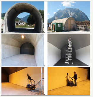
i. Original condition of the Junger test tunnel
ii. Exterior view of the for the research project adapted test tunnel with closed tunnel portal and storage of the concrete road in front of the tunnel
iii. Adapted test tunnel with black tunnel portal and concrete road
iv. Test tunnel with tarmac road, tunnel coating acceptance and coated roof „contaminated“
v. Illumination measurement conducted by MA 39 (=Municipal Authority for Testing, Monitoring and Certification of the City of Vienna)
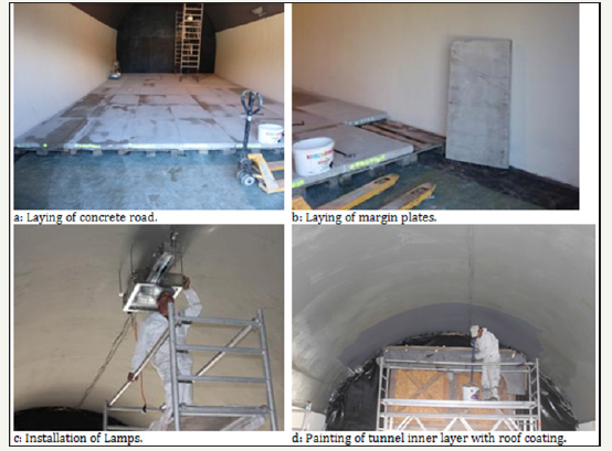
For the measurements one of the two concrete roads, depending on the evaluation condition, was moved or the tarmac surface was retained, the lighting, provided by the company Broll was installed and equipped with the necessary controlling. The company Electric Special installed two luminance sensors to determine the luminance on the tunnel´s inner layer wall as well as on the road surface. During the trial operations the control cabinet and the control technology were tested using three types of lamps (LED, NAV, HQI). The setting was designed to reach a basic luminance of 10cd/m² on the road surface with all three types of lamps. Figure 7 depicts the process of the preparation measures for the measurements of the resp. combinations of roof colour, tunnel walls and road surface.
figure:7 Creation of evaluation conditions in the adapted test tunnel
Measurements
During the measurements various evaluation conditions (Table 1) were analysed. First task was the construction of the respective surfaces of the tunnel walls by coating them with colours resp. materials. Then, in each case, the road surface resp. the tunnel roof was adapted to the evaluation condition that was to be measured. Figure 8 shows the work process. After the completion of the creation of an evaluation condition according to Table 1, the mounting of one of the three analysed tunnel lighting types took place.
figure:8 Working steps in the test tunnel in Irdning.
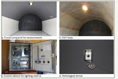
figure:9 Measurement of the visibility analysis of objects in the tunnel by different surfaces a: car dummy, b: shooting of the picture in the darkened tunnel.

The measurement took place in the lightproof sealed tunnel. The lamps were all adjusted to reach a luminance of 10cd/m² on the road surface. The luminance of the tunnel´s inner shell wall was also integrated into the measurement. After a constant operation was guaranteed, the measurement could be completed and the lamps were exchanged in each case. Additionally to the metrological quantification of the impact, the changes in the lighting situation of the tunnel were documented on photos. A car dummy was always positioned on the same spot in the tunnel for the optical observation. The measurements (head light distance) of the car dummy were adapted to the reduced tunnel measurements. In order to guarantee comparability, a camera with a constant aperture (4,5), a constant zoom (18mm) and regulated ISO-adjustment (3200) was used. Various pictures during different lighting settings, some with and some without people on the road were taken. Figure 9 shows the car dummy that was used as well as the shooting of the photos in a darkened tunnel.
Results and Discussion
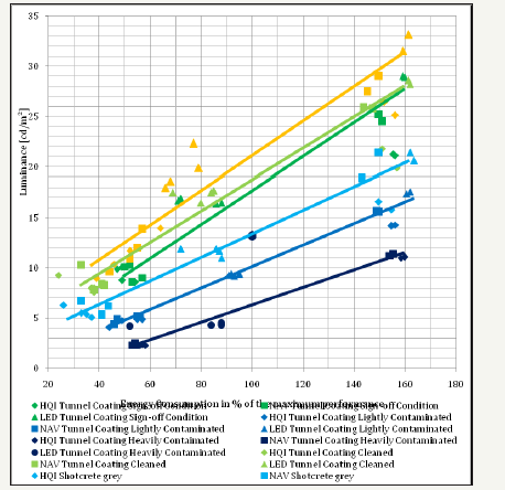
In the course of the research project 36 evaluation conditions were created and analysed in the test tunnel. The results of the measurements and the according analyses are depicted in the form of diagrams. The power of the three lamp types HQI, NAV and LED are comparable to 100, 100 and 105 watts. The lamps´ performance data needed to be extrapolated for the road surface tarmac, as none of the lamps reached the for the comparison necessary 10cd/m² lighting intensity of the road surface at 100% of their performance range. Figure 10 shows the luminance on the tunnel walls depending on the necessary luminance of 10cd/m² of the necessary power of the lamps on the road surface. The data points are being approximated depending on the luminosities on the tunnel wall surface using linear functions. Doing so the various tunnel paint systems can be ranked by their lighting intensity independent from the road surface or the lamp system.
Influence of the road surface
To begin with the measured values can be divided into two groups. The measured value „road surface asphalt“, calculated using extrapolation, ranging between 140 and 165 % of the maximum performance, forms the dataset with the highest power consumption. The high lamp performances result inevitably in relatively high lighting intensities on the tunnel walls. The second data cloud includes the measured values of the road surfaces “common exposed aggregate concrete” and “light exposed aggregate concrete”. Even with clear allocation of data points, no general distinction between the two road surfaces could be made. All 4 data points “LED tunnel coating light contamination” are located on approx. one line for example and only show little discrepancies in the power consumption. In general the LED-lamps can be demarcated in the data cloud (see Figure 10, marked by the dotted line). They provide the highest luminance on the tunnel wall during medium energy consumption.
Influence of the tunnel wall
As expected, the shotcrete in white delivers the best result. Regardless of road and lamp type, it presents the highest lighting intensities on the tunnel wall. In comparison of the shotcrete in white under NAV and HQI lighting, the white shotcrete also performs best, but the lighting intensities can absolutely be compared to the tunnel coating „sign-off condition“ and „cleaned“. The differences here are only minor. The tunnel coatings „acceptance condition“and „cleaned“show definitely comparable progressions in Figure 10 too. The grey shotcrete again delivers better values than the lightly resp. heavily contaminated tunnel coating. The heavily resp. lightly contaminated tunnel coating presents the lowest values with 2,5- 10cd/m² resp. 5-15cd/m².
In general it can be said, that the influence of a cleaned resp. new tunnel wall colour on the power consumption that is necessary for the lighting of the road surface with a light intensity of 10cd/m² is little. This becomes apparent with the analysis of the dataset with the lamp types HQI and NAV at the left lower area of the diagram in Figure 10. During NAV and HQI lighting, all evaluation conditions result in similar energy consumption, ranging between approx. 40 and 60% of the maximum power. Though, one obvious benefit of a tunnel cleaning is the increase in road safety. The brightness of the tunnel wall for example increases from „heavily contaminated“ to „cleaned“ from 2,5cd/m² to 8-10cd/m², resulting in a threefold increase of the irradiance of the tunnel wall.
figure:10 Measurement of the visibility analysis of objects in the tunnel by different surfaces a: car dummy, b: shooting of the picture in the darkened tunnel.
Results of the luminance measurements conducted by the MA 39 (=municipal authority for testing, monitoring and certification of the city of vienna)
The Municipal Authority for Testing, Monitoring and Certification of the City of Vienna (Municipal Authority 39) was assigned to conduct a metrological determination of the luminance and the colour information of tunnel surfaces in various evaluation conditions. The measurement of the luminance and the colour information took place situational following the ÖNORM Standard EN 13201-4: 2005 [6], using a spatially resolved luminance camera at a height of 1,5m. A photometer equipped with an illumination measuring head was used as instrument. Figure 11 depicts the average values of the luminance measurements (average values of lamp types HQI, NAV, LED) on different roads. The lighting intensities during the same illumination levels are more than 5 times higher on concrete roads (exposed aggregate concrete light: 16,9cd/m², exposed aggregate concrete common: 15,0cd/m² and asphalt: 2,9cd/m²).
figure:11 Luminance of the tunnel wall on various roads and at various measuring angles. In each case the weighted averages of the evaluation condition „roof contaminated“ and „roof cleaned“ as well as the lamp types NAV, HQI and LED are shown.
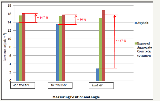
figure:12 Luminance images of the test tunnel using asphalt, exposed aggregate concrete, common and exposed aggregate concrete, light and cleaned ridge. Tunnel coating: tunnel wall acceptance condition (Fig. MA 39, Vienna).

Figure 12 shows an excerpt of the luminance images for the tunnel wall coating „sign-off condition“, that was made by MA 39. The luminance images clearly depict the differences between asphalt (blue) and the concrete roads. Figure 13 shows the results of the luminance measurements, conducted by MA 39, graphically using bar charts for „tunnel wall acceptance condition“. In order to create better comparability, the evaluation conditions are shown with cleaned ridges. The luminance of the tunnel walls is significantly increased on concrete roads, whereby the best results can be achieved with the bright concrete road. Thereby the luminance increases by an average of 21% during the change from „asphalt“ to „exposed aggregate concrete, bright“ resp. by 15% during the change to exposed aggregate concrete, common. The difference in the luminance of the road surface is even clearer:
figure:13 Luminance on tunnel wall (viewing angles 45° and 90°) as well as road surface using „tunnel coating acceptence condition“ and different road surfaces and lights (all cleaned ridge).
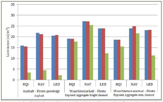
Table 3:

Despite of the high luminance of the tunnel wall, the luminance of the road surface asphalt does not exceed 5cd/m².
Illumination of road surfaces - increase in road safety
In 1987 already, McIntosh & Bruce [7] reported about the positive impact of concrete roads in comparison to asphalt roads with regard to reflectivity and the related increased brightness and visibility of objects in traffic. Within the framework of the research project and in order to visualise the increased road safety, tests were conducted under uniformed and comparable conditions in a test tunnel and photographs were taken. To demonstrate the increase in road safety, the tests were reconstructed under constant and therefore comparable conditions in the test tunnel and photos were taken within the framework of the research project. The tests took place in the darkened tunnel using the car dummy resp. with the high and low beam lights turned on using the same camera settings. Figures 14-16 show comparable photos of the visibility conditions without light in the tunnel.
figure:14 Wall lightly contaminated, roof cleaned, concrete common.
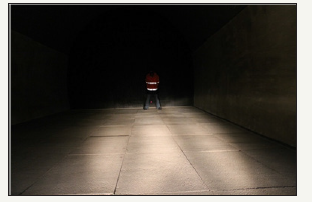
In general concrete roads are significantly brighter and better illuminated by low beam. Differences between exposed aggregate concrete bright and exposed aggregate concrete common are possibly detectable by the slightly darker resp. softer colour of the light beam in Figure 14, compared to the whiter light beam in Figure 15. The enhanced brightness and the increased reflectivity of the concrete make it easier to detect objects - such as a pedestrian - significantly earlier and better. The asphalt road, depicted in Figure 16, is only weakly illuminated by the low beam and therefore the detection of objects on the road is delayed and decreased. Similar results can be derived using high beams. Concrete reflects a higher ratio of the light and therefore leads to a better illumination of the traffic area. The differences are still not as high as when using the low beam, as the high beam is adjusted higher and more focused and therefore less light reaches the road and reflects from there.
figure:15 Wall lightly contaminated, roof cleaned, concrete bright.
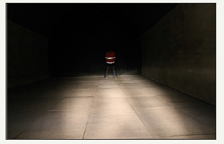
figure:16 Wall lightly contaminated, roof cleaned, asphalt.

Savings of the lighting costs
The evaluation of the lighting costs took place based on the energy consumption in relation to the maximum output. Figure 17 presents the mean value of the actual energy consumption of the maximal output of an HQI-lamp during the lighting intensity of different road surfaces of 10cd/m² over all tunnel wall colours in percent. For asphalt, the extrapolated performance values from Figure 10 were used and compared to the mean value of the concrete roads „exposed aggregate concrete bright” and “exposed aggregate concrete common”.
It is remarkable that in order to reach a luminance of 10cd/ m², high performance of a lamp for asphalt roads is necessary, sometimes reaching four times the energy consumption that is needed when using a concrete road. The reason for this big difference is that the data of these measurements comes from one lamp only. The asphalt surface is designed in such a way that lamps even at 100% of their maximum output do not reach the necessary lighting intensities of 10cd/m² on the road surfaces. In order to restore comparability, the performances were then aligned using linear extrapolation. The influence of the tunnel wall colour is insignificant to the lighting intensity on the road and therefore also for the energy consumption and is consquently not presented in this Figure.
figure:17 Mean value of the performance of an HQI-lamp in% of its maximum performance during a lighting intensity of 10cd/m² for all examined road surfaces and tunnel wall colours.

Conclusion
In the course of the research project a variety of different lighting situations were simulated and subsequently evaluated. The positive impact of a concrete road on the photometric characteristics of a tunnel can be assessed as substantial. In order to guarantee the necessary luminance on the road, concrete roads require significantly lower lamp performance independent from the lamp type. At the same time, the lamp power can theoretically be decreased by two thirds compared to asphalt roads. The influence on the necessary lamp wattage between common concrete pavements and concrete pavements that have been supplemented with titanium oxide is negligible. In general, objects, such as a pedestrian for example, can be detected significantly earlier and better due to increased brightness and the better reflectivity of the concrete. The concrete reflects a higher proportion of the light and therefore ensures a better indirect lighting of the traffic area. The differences between “exposed aggregate concrete bright” and “exposed aggregate concrete common” can hardly be detected on the pictures with simulated car headlights and pedestrians. The luminance images of the MA 39 visualise the small difference in luminance on the roads and the tunnel walls and confirm the subjective impression. The measured lighting intensities also confirm this observation: The measured lighting intensities also confirm this observation: The luminance during the same illumination level is approx. 450% higher on concrete roads.
References
- (2008) DIN 67 524: Beleuchtung von Straßentunneln und Unterführungen- Teil 1: Allgemeine Gütemerkmale und Richtwerte.
- (2011) DIN 67 524: Beleuchtung von Straßentunneln und Unterführungen- Teil 2: Berechnung und Messung.
- (2014) RVS 09.02.41: Tunnel. Tunnelausrüstung. Lichttechnik. Beleuchtung. Österreichische Forschungsgesellschaft Straße -Schiene- Verkehr. Wien.
- (2011) RVS 08.17.02: Technische Vertragsbedingungen. Betondecken. Deckenherstellung. Österreichische Forschungsgesellschaft Straße- Schiene-Verkehr.
- (2010) ONR 23303: Prüfverfahren Beton (PVB)-Nationale Anwendung der Prüfnormen für Beton und seiner Ausgangsstoffe. Austrian Standards Institute.
- (2005) ÖNORM EN 13201-4: „Straßenbeleuchtung. Teil 4: Methoden zur Messung der Gütermerkmale von Straßenbeleuchtungsanlagen“. Austria Standards Institute, Vienna, Austria.
- McIntosh, Bruce (1987) Do Concrete Streets really reflect up? Concrete International 9 (7): 24-25.
© 2018 Gerald Maier. This is an open access article distributed under the terms of the Creative Commons Attribution License , which permits unrestricted use, distribution, and build upon your work non-commercially.
 a Creative Commons Attribution 4.0 International License. Based on a work at www.crimsonpublishers.com.
Best viewed in


.jpg)


 Editorial Board Registrations
 Submit your Article
 Refer a Friend
 Advertise With Us
.jpg)


.jpg)


.bmp)
.jpg)
.png)
.jpg)


.jpg)


.png)

.png)


.png)


