- Submissions

Full Text
Advancements in Civil Engineering & Technology
Single Crystal Organic Photovoltaic Cells
Masahiro Hiramoto* and Mitsuru Kikuchi
National Institutes of Natural Sciences, Institute for Molecular Science, Japan
*Corresponding author: Masahiro Hiramoto, National Institutes of Natural Sciences, Institute for Molecular Science, Japan
Submission: April 20, 2018;Published: May 03, 2018

ISSN: 2639-0574 Volume1 Issue2
Mini Review
Carrier mobilities of organic single crystals reached greater than 10 cm2 V-1s-1 [1,2]. Such high mobility was observed for carriers moving laterally through the material due to π-π stacking parallel to the crystal surface. Conventional organic solar cells are built vertically on indium tin oxide (ITO) glass substrates with a sandwich-type structure [3-6]. However, the thickness of such solar cells with blended layers of donor (D) and acceptor (A) molecules, which are indispensable to dissociate excitons, is limited to just around 100nm due to the problem of carrier collection arising from imperfections in the electron and hole transport routes in the blended layer. If the photogenerated electrons and holes can be transported laterally and collected, we can be freed from the vertical transport of carriers and freed from the limitation to the vertical thickness of the cell.
The concept of the lateral type cell is shown in Figure 1a. Electrons move laterally through the single crystal substrate. A pair of electrodes separated by a distance L is deposited in parallel on the crystal surface. A layer of organic semiconductor acting as a donor (DBP) is inserted between the organic single crystal (NTCDA) substrate, which acts as an acceptor. At the D/A interface, excitons dissociate into electrons and holes under light irradiation. Since the photogenerated holes move in the vertical direction, the distance to the electrode is equal to the film thickness of 30nm. On the other hand, since the photogenerated electrons move laterally, the inter-electrode distance (L) is at least 30μm. Thus, the lateral distance is 1000 times the vertical distance, which means that the cell characteristics are dominated by the electron transport. The right hand edge of the hole collection electrode can be regarded as the starting point for the electrons (broken blue line). The range of the electrons (Le) is expressed by eq. (1).

figure 1a: Configurations of the lateral organic single crystal cell.

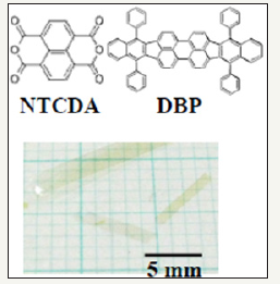
Where , μe τe and E are the electron mobility, the electron lifetime, and the electric field, respectively. The inter-electrode distance L can be varied (Figure 1a). When L is within the range Le (Le>L) the electrons can be collected at the electrode, but when it is not (Le< L) they cannot. So, the photocurrent decreases when L is at around Le. In this mini-review, we describe lateral electron transport and electron collection in organic photovoltaic cells using NTCDA single crystal (Figure 1b).
figure 1b: Chemical structures of NTCDA and DBP. A photograph of NTCDA single crystal is also shown.

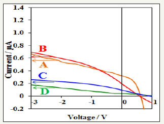
Figure 2a shows the current-voltage (J-V) characteristics of cells with L=20, 30, 50, 100μm under irradiation of 10 suns. When L increases from 20 (orange curve A) to 30μm (red curve B), the magnitudes of photocurrents in the saturated region of reverse direction from -1 to -3 V coincided well. When L increases from 30 (red curve B) to 50μm (blue curve C), the photocurrent decreases significantly. A further increase of L from 50 (blue curve C) to 100μm (green curve D) causes a further, moderate decrease in photocurrent. This result suggests that the effective electron transport occurred within 30μm in the lateral direction, i.e., the electron range (Le) was around 30μm.
figure 2a: J–V characteristics of lateral cells with L=20μm (orange curve A), 30μm (red curve B), 50μm (blue curve C), and 100μm (green curve D) under irradiation of 10 suns.

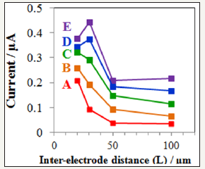
In Figure 2b, the photocurrent-L relationships at constant values of E of 1,2,3,4, and 5x10² Vcm-1, which are around the magnitude of the built-in field (2x10² V cm-1). Again, sharp decreases in photocurrent were confirmed between L=30 and 50μm. Photocurrent was almost constant below L=30μm under the sufficient electric fields (green dots C, blue dots D, purple dots E). Therefore, we concluded that the electron range (Le) is around 30μm.
figure 2b: Dependence of the photocurrent on L at constant values of E of 1x10² (red dots A), 2x10² (orange dots B), 3x10² (green dots C), 4x10² (blue dots D), and 5x10² Vcm-1 (purple dots E).

figure 2c: Schematic illustrations of the relationship between L and Le in the lateral cells.

Figure 2c shows schematic illustrations of lateral cells with L=30, 50, and 100μm. Le is 30μm. When Le< L, a small number of electrons can reach the collection electrode. This situation is realized for L=50 (Figure 2c, middle) and 100μm (Figure 2c, bottom). When Le>L, most of the electrons can reach the collection electrode. This situation is realized for L = 30μm (Figure. 2c, top).
By eq. (1), electron lifetime τe was calculated to be 0.52ms. The electron mobility μe of the NTCDA single crystal was 2.9x10- 2 cm2 V-1 s-1. The value of τe obtained (0.52ms) is of the order of milliseconds, and would enable an electron range Le of the order of millimeters to be obtained if single crystal organic materials with an electron mobility μe of 1cm2 V-1s-1 were used [2].
The operation of a single crystal organic photovoltaic cell was demonstrated. An electron range (Le) reached 30μm. The large value of τe close to the order of a millisecond indicates the possibility of having electron ranges of the order of millimeters. Near future, we would be freed from the vertical transport of carriers and freed from the limitation to the vertical thickness of the organic solar cell.
References
- Takeya J, Yamagishi M, Tominari Y, Hirahara R, Nakazawa Y, et al. (2007) AlAs∕GaAs micropillar cavities with quality factors exceeding 150.000. Appl Phys Lett 90: 1021120.
- Chesterfield RJ, McKeen JC, Newman CR, Ewbank PC, Filho DA, et al. (2004) rganic Thin Film Transistors Based on N-Alkyl Perylene Diimides: Charge Transport Kinetics as a Function of Gate Voltage and Temperature. J Phys Chem 108 (50): 19281-19292.
- Hiramoto M, (2017) Organic Solar Cells, In: Kasap S & Capper P (Eds.), Part E Novel Materials and Selected Applications, Springer Handbook of Electronic and Photonic Materials (2nd edn), Springer International Publishing AG, Switzerland, pp. 1239-1338.
- Hiramoto M (2017) Energetic and nanostructural design of smallmolecular- type organic solar cells, In: Rice SA & Dinner AR (Eds.), Advances in Chemical Physics, John Wiley & Sons, USA, pp. 137-204.
- Tang CW (1986) Two‐layer organic photovoltaic cell. Appl Phys Lett 48: 183.
- Hiramoto M, Fujiwara H, Yokoyama M (1991) Three‐layered organic solar cell with a photoactive interlayer of codeposited pigments. Appl Phys Lett 58: 1062.
© 2018 Masahiro Hiramoto. This is an open access article distributed under the terms of the Creative Commons Attribution License , which permits unrestricted use, distribution, and build upon your work non-commercially.
 a Creative Commons Attribution 4.0 International License. Based on a work at www.crimsonpublishers.com.
Best viewed in


.jpg)


 Editorial Board Registrations
 Submit your Article
 Refer a Friend
 Advertise With Us
.jpg)


.jpg)


.bmp)
.jpg)
.png)
.jpg)


.jpg)


.png)

.png)


.png)


