- Submissions

Full Text
Advancements in Civil Engineering & Technology
A Pitched Roof with Forced Ventilation to Limit Solar Gains
Enrico Caffagni, Antonio Libbra, Alberto Muscio* and Luca Tarozzi
Energy Efficiency Laboratory, University of Modena and Reggio Emilia, Italy
*Corresponding author: Energy Efficiency Laboratory, University of Modena and Reggio Emilia, Italy
Submission: April 09, 2018;Published: May 03, 2018

ISSN: 2639-0574 Volume1 Issue1
Abstract
An effective approach to ventilation of pitched roofs has been developed. It is aimed at mitigating summer overheating of inhabited rooms located immediately below the roof. The air flows in a ventilation layer made of parallel ducts and built between roof coverings and insulation, thus subtracting heat from the roof structure. It is then collected by a header and eventually discharged into the atmosphere by a extraction fan. The problem of obtaining a homogeneous flow distribution in the ventilation layer is solved by a very simple regulation mechanism, placed in the header and adjusted on site. The adjustment procedure is based on measurements of surface temperature distribution performed by an infrared camera
Keywords: Forced ventilation; Infrared thermography; Solar gain; Thermal comfort; Ventilated roof
Introduction
Summer overheating of buildings due to solar irradiation is a major problem in hot and temperate climates. It becomes absolutely critical when the attic is inhabited and the thermal inertia of the roof structure is low. Even if insulation is present, the roof temperature may rise easily to an uncomfortable level. The problem cannot be simply addressed by conditioning the air as the ceiling immediately below the roof remains hot, thus yielding an unsatisfactory radiant and operative temperature below. Moreover, air conditioning of inhabited attics can be extremely expensive in terms of energy need. The issue described above is addressed by several approaches. With low-slope roofs, the roof surface can be coated by materials with very high value of solar reflectance and thermal emittance. A ‘cool roof’ is thus obtained [1]. The same approach cannot be used with steep-slope roofs, however, as solar radiation would be reflected onto the buildings nearby. Moreover, common cool roof products have white or very light color. As a result, they are difficult to use in most ancient or traditional south-European buildings, which typically have roofs covered by terracotta tiles. On the other hand, in places like the historical centers of Italian cities the attic immediately below the roof is often inhabited.
A practice to reduce the temperature of steep-slope roofs is to build a ventilation layer, made of climbing parallel ducts, between the tile covering and the insulation. Airflow is driven by natural convention, with the air entering the ducts through inlet openings located immediately below the gutter, then cooling the roof coverings from below and finally going out at the roof top through shielded outlet openings. The airflow, however, may be very weak in free ventilation roofs and the cooling effect inadequate, if the ventilation layer is thin [2-6]. Moreover, even a feeble breeze can inhibit completely air circulation.
figure 1: Forced ventilation of a steep-slope roof.

To overcome the above mentioned limits, an effective approach to roof ventilation has been developed [7]. Similarly to ventilated roofs wit free convection, the air enters a ventilation layer of parallel ducts built between roof coverings and insulation, flows in the ducts and subtracts heat from the roof structure. It is then collected by a header at the roof top and eventually discharged in the atmosphere by a extraction fan mounted on top of a chimney (Figure 1). The ventilation is thus independent of weather conditions or inadequate design of the ventilation layer. Power consumption for air conditioning can also be decreased greatly, whereas power consumption of the fan is relatively low. Moreover, ventilation can be stopped when not desired, for example in winter.
A homogeneous flow distribution is not automatically obtained in the ventilation layer by the layout sketched in fig. 1. In fact, the pressure field along the header would promote a strong airflow in the ducts closer to the extraction chimney and a very weak airflow in the farther ducts. The problem has been solved, however, by a very simple regulation mechanism, for which a patent request is being filed. The mechanism is placed in the header and can be adjusted easily on site. The adjustment process is based on measurements of surface temperature distribution performed by an infrared camera.
Experimental Analysis
A small scale prototype of a ventilated roof with tile covering was built to test the forced ventilation approach (Figure 2). It can be shown by dimensional analysis that the fluid dynamic behavior of the prototype is not quantitatively representative of that of a full scale system; nevertheless the response of the prototype to the settings of the regulation mechanism is expected to be similar. The prototype was therefore used to test the mechanism and refine some practical aspects of its implementation.
figure 2: Small-scale prototype of a roof with terracotta tile covering.

The external surface of the roof model was heated by a lamp system simulating the solar radiation. The surface temperature was then monitored by an AVIO TVS-620 infrared camera [8], in order to individuate the flow distribution in the ventilation layer and adjust the regulation mechanism. In fact, a direct relationship is expected to exist between the steady-state surface temperature and the air velocity in the duct below.
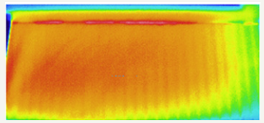
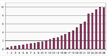
The results of the laboratory analysis confirmed the effectiveness of both the regulation mechanism and the adjustment procedure based on infrared thermography. Figure 3 shows the surface temperature distribution measured without regulation mechanism. The lowest temperatures are above the ducts closest to the fan and the extraction chimney (on the right). A confirmation was given by a hotwire anemometer, which measured the flow rate distribution shown in Figure 4.
figure 3: Surface temperature distribution on the roof covering without regulation mechanism.

figure 4: Flow rate distribution (percentage of total airflow) measured in the ducts of the ventilation layer without regulation mechanism.

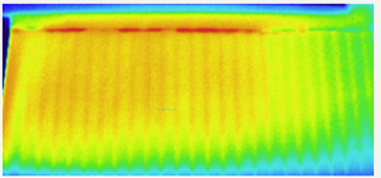
figure 5: Surface temperature distribution on the roof covering with regulation mechanism and optimized adjustment.

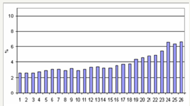
figure 6: Flow rate distribution (percentage of total airflow) measured in the ducts of the ventilation layer with regulation mechanism and optimized adjustment.

Figure 5 shows the surface temperature distribution measured with the regulation mechanism, with optimal adjustement obtained after a small number of trials. The flow rate distribution was again verified by a hotwire anemometer, obtaining the plot in Figure 6. Even if the flow rate is still higher in the ducts closest to fan and chimney, all ducts receive an adequate flow rate. As results, the average surface temperature of the roof is much lower than without the regulation mechanism.
Conclusive Remarks
Either the approach to roof cooling by forced ventilation or the thermographic procedure to achieve an optimized regulation of the ventilation system were verified. A satisfactory flow distribution was achieved after a small number of trials, using methods that can be easily replicated in full scale.
Current analysis is focused onto the design of full scale roof ventilation systems and the development of the regulation mechanism for roof geometries more complex than that considered here.
Acknowledgments
The authors wish to thank Prof. Giovanni S. Barozzi, Eng. Sergio Trapasso, and Dr. Paolo Levoni for technical collaboration and advice.
References
- Akbari H, Cartalis C, Kolokotsa D, Muscio A, Pisello AL, et al. (2016) ZLocal climate change and urban heat island mitigation techniques–the state of the art. Journal of Civil Engineering and Management 22(1): 1-16.
- Ciampi C, Leccese F, Tuoni G (2005) Energy analysis of ventilated and microventilated roofs. Solar energy 79(2): 183-192.
- Dimoudi A, Androutsopoulos A, Lycoudis S (2006) Summer performance of a ventilated roof component. Energy and Buildings 38(6): 610-617.
- D’Orazio M, Di Perna C, Principi P, Stazi A (2008) Effects of roof tile permeability on the thermal performance of ventilated roofs: Analysis of annual performance. Energy and Buildings 40(5): 911-916.
- Biwole PH, Woloszyn M, Pompeo C (2008) Heat transfers in a doubleskin roof ventilated by natural convection in summer time. Energy and Buildings 40(8): 1487-1497.
- Susanti L, Hommab H, Matsumoto H, Suzuki Y, Shimizu M (2008) A laboratory experiment on natural ventilation through a roof cavity for reduction of solar heat gain. Energy and Buildings 40(12): 2196-2208.
- Tarozzi L, Caffagni E, Alberto M (2007) Assessment of flow distribution in a roof with forced ventilation by infrared thermography.
- Nippon Avionics Co. Ltd, Operation Manual for Neo Thermo TVS-600 Series, 2002.
© 2018 Alberto Muscio. This is an open access article distributed under the terms of the Creative Commons Attribution License , which permits unrestricted use, distribution, and build upon your work non-commercially.
 a Creative Commons Attribution 4.0 International License. Based on a work at www.crimsonpublishers.com.
Best viewed in


.jpg)


 Editorial Board Registrations
 Submit your Article
 Refer a Friend
 Advertise With Us
.jpg)


.jpg)


.bmp)
.jpg)
.png)
.jpg)


.jpg)


.png)

.png)


.png)


