- Submissions

Full Text
Evolutions in Mechanical Engineering
Transmission for Hybrid and Electric Vehicles
Khadeev RG*
State Research Test Institute of Military Medicine, Russia
*Corresponding author:Khadeev RG, State Research Test Institute of Military Medicine, Russia
Submission: June 9, 2023;Published: September 15, 2023

ISSN 2640-9690 Volume5 Issue1
Abstract
The article proposes the design of a simple transmission that allows, in the entire range of motion, to automatically change the torque and gear ratio on the driven shaft. It allows the drive motor in all driving modes from the moment of start to operate at optimal speed with full power output. The use of such a transmission in hybrid vehicles, and especially in electric vehicles, is the most cost-effective and allows overcoming and simplifying some of the complex elements of technological solutions.
Keywords: Planetary differential; Current generator; Torque; Transfer ratio
Introduction
Figure 1:1. Motor shaft; 2. Coupling; 3. Generator rotor; 4. Generator stator; 5. The crown of the planetary differential; 6. Satellites; 7. Planetary differential carrier; 8. Central gear; 9. Driven shaft.

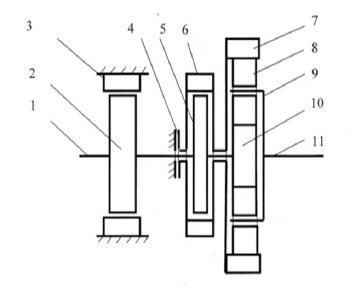
The transmission for most vehicles can be configured according to the scheme presented here. Such a transmission in automatic mode provides the entire required range of torque conversion and gear ratio. It consists of two main elements: A planetary asymmetric differential and a generator connected to it, located on the drive shaft. The principle of its operation is based on comparing the force necessary for the movement of the vehicle, with the Ampere force arising from the generation of current by the generator, considering the asymmetry of the differential. The scheme for implementing such a solution for electric transport is described in [1] and shown in Figure 1. Shaft 1 of the traction motor, preferably synchronous, is connected to the rotor of generator 3 and the central wheel of planetary gear 8. The stator of generator 4 is connected to the crown of planetary gear 5, and freely rotates around shaft 1 and is connected to clutch 2, which can connect it to the housing. Satellites 6, mounted on the carrier 7, run around the central wheel 8, which is connected to the driven shaft 9. The rotation of shaft 1 of the traction motor is transmitted to the input of the differential, the central wheel 8 and the generator rotor 3. The output of the differential, the carrier 7, is connected to the driven shaft 9, transmits torque to the drive wheels, and the second output, crown 5, tends to rotate in the opposite direction, but the generator 4 stator connected to it, in the presence of an electrical load in the generator circuit, is dragged behind the rotor 3 and rotates the differential around the axis. Both channels transmit rotation to the driven shaft. Clutch 2 can connect the stator of generator 4 with the housing. At the same time, the stator stops and rotation is transmitted to the driven shaft with the maximum torque for this differential (Figure 2)
Figure 2:1. Drive shaft; 2. Electric motor rotor; 3. Motor stator; 4. Coupling; 5. Generator rotor; 6. Generator stator; 7. The crown of the planetary differential; 8. Satellites; 9. Planetary differential carrier; 10. Central wheel; 11. Driven shaft.

If necessary, when the stator is stopped, the generator is used as an additional electric motor and is also used to start the traction synchronous electric motor. The synchronous motor has several advantages. These are efficiency, smaller dimensions and weight with the same power, high overload capacity. Its use is complicated by the fact that it only works at constant speed. This explains its rare use in transport, where engine speed cannot be constant. But in this case, any engine can operate at constant speed from the moment of start, and the change in gear ratio and torque is made in the transmission mechanism. A synchronous electric motor connected to the network is economical at idle. When a load appears on the motor shaft, it maintains speed, automatically increasing its power. He doesn’t need control. The electric motor may not necessarily be synchronous, the transmission can work with any electric motor. The main advantage of such a transmission is that when the load on the driven shaft increases, it slows down, the rotation is transmitted to a greater extent through the gears, while the torque on the driven shaft increases and, conversely, when the load on the driven shaft is lightened, it accelerates and the gear ratio transmission is automatically reduced. Is only needed to control the operation of the generator. With an increase in the current generated by the generator and an increase in the induction force that occurs between the rotor and stator of the generator, the slip between them decreases, the rotation of the differential elements relative to each other decreases, and the movement on the driven shaft is transmitted to a greater extent through the rotation of the differential around the axis, while the total the gear ratio decreases, the speed of rotation of the driven shaft increases. The torque on the driven shaft, in the case of using such a transmission, increases by 2.5 times relative to the torque capability of the electric motor used. This greatly simplifies and reduces the cost of the design, and if we consider the fact that a synchronous motor is much more economical than any other, and that it operates in the optimal mode during the entire movement, the expediency of using such a design can be considered undeniable. Such an increase in torque is sufficient for dynamic acceleration because the generator, stopped by clutch 2, works as an additional engine and adds another half of the engine power to the output on the driven shaft, and the engine is operating at optimal mode and there is no clutch mechanism.
The electric current generated by the generator returns to the network and feeds the traction motor, the excitation winding, if the electric motor is synchronous, as well as other consumers. With this method of transmission of rotation on electric trains, there will be no need for a gearbox connecting the traction motor with a wheel pair, as well as an expensive and still imperfect high-voltage element base for control. For hybrid transport, the transmission is fundamentally arranged in the same way [2], as for electric transport, only the electric current generated by the generator is consumed to a greater extent by the electric motor, the rotor of which is installed on the drive shaft and rotates the drive shaft together with the vehicle motor, compensating for production costs on the electric current generated during transmission operation. It is important: both the engine and the generator are rigidly mounted on a common shaft. There is no need for sliding current collectors for power transmission, which means that the resource, efficiency and reliability are increased. You can also synchronize the operation of the magnetic fields of the engine and generator, use the Hall effect to control by installing the device on the shaft. The torque of such a differential is limited. Its maximum value can be reached under the condition that the crown and the central wheel are taken in the ratio of 1.618. With such a ratio of the number of teeth of the gears of the crown (zcr.) and central wheel (Zc.w.), the gear ratio of the planetary gear to the driven shaft icarrier.

The torque can increase up to this value from the torque value on the drive shaft. But the energy of the drive shaft is divided into the carrier and the crown, and from the central wheel to the crown, the moment acts in the opposite direction with the gear ratio:

The crown, on the other hand, transmits rotation to the carrier from the force that drags the stator behind the generator rotor, which is connected to the drive shaft, acting in the direction of rotation of the drive shaft. Its value can be determined through the gear ratio icr..

This force counteracts the reverse torque and balances it, which allows you to get a torque on the driven shaft that is 2.6 times the torque on the drive shaft. With an increase in the gear ratio of the planetary gear, the maximum torque on the driven shaft decreases, and with a selected ratio corresponding to the number φ, the balance of forces in the planetary differential is observed to ensure the transmission of torque to the driven shaft. If the ratio of the crown gears and the central gear, for example, is set equal to two, then the gear ratio on the carrier will be equal to three. But on the driven shaft, the torque will not increase, but decrease, because the gear ratio from central wheel to the crown will increase to two and decrease to one and a half from the crown, and this will lead to a decrease in the gear ratio on the driven shaft to two and a quarter.
When accelerating a vehicle with such a transmission, the engine operates in the optimal mode, there is no clutch mechanism, and the electric motor will add another third of the engine power. This provides enough momentum during acceleration. Both outputs of the differential rotate the driven shaft in the same direction, and the energy generated by the generator is also fully utilized, losses are minimal. Modern generators of this power have an efficiency of eighty-five percent. But one way or another, electricity is in any case necessary for the operation of vehicle systems, for excitation power, if the electric motor is synchronous [3], for battery charging, for lighting and heating, therefore, it is incorrect to consider losses when comparing transmission in terms of efficiency. Two percent is lost in planetary gear. One percent of the traction drive power will be consumed by the inverter. It is necessary to add another percentage for losses in seals and bearings. It turns out in any case less than in modern transmissions. In addition, in such a transmission there is no large increase in losses with the development of the resource, the losses grow insignificantly. Such a transmission operates automatic and if necessary, electronically controlled throughout the entire range. No switching, no disconnection of the engine from the driven shaft. The engine always runs at optimum speed. Even at the start, when the vehicle is stationary, the traction motor operates at optimal speed, while the generator stator rotates in the opposite direction and the maximum torque is realized on the driven shaft. Both the electric motor operating in the generation mode and, in fact, the generator can participate in recuperation during braking. An additional power impulse during start-up and acceleration can be given by a generator used as an engine, the stator of which must be coupled to the housing. This transmission can be used on conventional vehicles with an internal combustion engine. Such a vehicle will not need a starter, generator or clutch mechanism. Due to the high responsiveness of electrical systems, such a transmission can be used as an anti-lock system during braking and traction control during acceleration.
References
- Khadeev RG (2022) Transmission for electric transport Eurasia science XLVII. International Scientific and Practical Conference, pp. 89-92.
- Khadeev RG, Transmission for a hybrid innovation in science and practice collection of scientific articles based on materials of the IX. International Scientific and Practical Conference, Research Center Bulletin of Science, pp. 28-32.
- Khadeev RG (2017) Synchronous motor for the vehicle. Engineering 9: 251-253.
 a Creative Commons Attribution 4.0 International License. Based on a work at www.crimsonpublishers.com.
Best viewed in


.jpg)


 Editorial Board Registrations
 Submit your Article
 Refer a Friend
 Advertise With Us
.jpg)


.jpg)


.bmp)
.jpg)
.png)
.jpg)


.png)

.png)


.png)


