
- About Us
- Guidelines
-

The Author ensures that the research has been conducted responsibly and ethically with adherence to all relevant regulations. read more..
- For Authors
- For Reviewer
- Manuscript Guidelines
- Membership
-
- Journals
- Reprints
- e-Books
- Videos
- Indexing
- Contact Us
 COVID-19
- Submissions


Full Text
Evolutions in Mechanical Engineering
Seismic Resistance of Turbine Equipment of Powerful Nuclear Power Plants
Serhii Palkov1* and Ihor Palkov2
1Head of the Thermal Calculations Sector, Design Department, JSC Ukrainian Energy Machines, Ukraine
2Deputy Chief Designer of Steam Turbines, Design Department, JSC Ukrainian Energy Machines, Ukraie
*Corresponding author:Serhii Palkov, Head of the Thermal Calculations Sector, Design Department, JSC Ukrainian Energy Machines, Ukraine
Submission: July 12, 2022;Published: January 31, 2023

ISSN 2640-9690 Volume4 Issue3
Abstract
The paper considers the methods of the design analysis of the seismic resistance for the components of operating nuclear power plants in at three-dimensional setting using the finite element method. An algorithm to confirm the seismic resistance of equipment by a calculation method is proposed, and the limits of its application are determined. A mathematical model of the equipment is developed, and an example of the determination of natural frequencies and stresses for a three-dimensional structure is given. Two main types of calculation were used–static and dynamic. The seismic resistance of the equipment was estimated on the example of the K-1000-60/1500 steam turbine condenser and calculated at a seismic intensity of 6 points on the MSK-64 seismic intensity scale. In the course of solving this problem, results of the stress distribution in the housing and other structural elements of the condenser due to the action of combined normal operation and design-basis seismic loads were obtained. The seismic resistance of the equipment was calculated using the finite element method. Results of the assessment of the spatial complex stress state of the steam turbine condenser design due to the action of combined normal operation and design-basis seismic loads are obtained.
Keywords: Floor response spectrum; Seismic resistance; Finite element; Natural frequencies; Equivalent stresses
Abbreviations: NPP: Nuclear Power Plants; IAEA: International Atomic Energy Agency; FEM: Finite Element Method; FE: Finite Elements; NO: Normal Operation; DBS: Design-Basis Seismic; FRS: Floor Response Spectrum
Introduction
Up-to-date safety requirements for Nuclear Power Plants (NPPs) regulate the mandatory analysis and assessment of their reliability and protection under all types of impacts such as operational, internal emergency, and extreme external of natural and man-made origin. Extreme external impacts include accidental and deliberate explosions, fires, flight vehicle (aircraft) crashes, intense electromagnetic radiation, earthquakes, floods, hurricanes, tornadoes, tsunamis, lightning strikes, volcanic eruptions, mudflows, avalanches, falls, slides, ground collapse [1-3]. As shown by a detailed analysis, among the extreme external impacts in terms of a complex of factors (geographic occurrence, frequency of occurrence, released energy and its intensity, unpredictability), seismic impacts are the most dangerous for NPPs [1-4]. Calculation for seismic resistance is an obligatory step in the verification of turbine equipment, and is used to determine the possibility of using in seismic zones of power plant equipment designed in accordance with the requirements of regulations. At present, requirements for the seismic resistance of power equipment have become obligatory in the design of not only nuclear, but also thermal power plants located in seismic zones.
The great attention paid to the issue of ensuring the seismic resistance of power plant equipment is determined not only by the risk of radioactive contamination of the environment, deaths of people, large material losses during earthquakes, but also the ability to significantly increase the reliability of equipment under normal operating conditions [4-10]. This is due to the fact that seismic resistance calculation is essentially an additional analysis of the entire structure under a dynamic effect, which has a wide range of frequencies from fractions to several tens of hertz, and includes almost all the operating and natural frequencies of equipment. As a result, already at the design stage, weak structural elements are detected, which cannot be detected by traditional methods of analysis. According to the general seismic-resistant design approach, the seismic resistance of a turbine is considered to be ensured if the design-basis seismic effect does not disrupt the turbine performance, and provides electricity generation with unguaranteed efficiency during and after the earthquake [4]. The relevance of this work consists in developing methods to increase the efficiency of the calculated substantiation of the seismic safety of power plant equipment by realizing the possibility of reducing the volume and cost of work caused by in-situ tests. The aim of the work is to study the possibility of replacing these tests with a numerical experiment while maintaining the required level of confidence and reliability of the seismic assessment of equipment.
Literature Review
Issues of the estimated assessment of the seismic resistance of equipment have been studied in the works of many prominent scientists and research institutes [1-5]. The seismic safety problem has an important place in the expert and regulatory activities of the International Atomic Energy Agency (IAEA). The following facts testify to the scope of attention to the problem of ensuring the seismic safety of nuclear facilities and primarily NPPs. Within the IAEA, a special department for seismic safety of NPPs regularly carries out expert missions at specific nuclear power plants in different countries, and periodically carries out multiyear international coordination programs. In particular, two such programs were aimed at investigating into the seismic safety of NPPs in Eastern Europe equipped with VVER-440 and VVER-1000 reactors, which are in operation, including in Ukraine [6]. The IAEA has published numerous manuals, reference books and guidelines for checking and ensuring seismic resistance of facilities, structures and process equipment of NPPs [7-9].
Problem Statement and Description of Calculation Methods
The calculation of equipment for seismic resistance in this work was performed using the Finite Element Method (FEM). To perform this calculation on a scale of 1:1, CAD modeling software was used to create a three-dimensional model of the K-1000-60/1500 steam turbine condenser (Figure 1). The design features of the condenser are described earlier in the paper [4]. In the calculation package, the geometric model was divided into Finite Elements (FE), the properties of materials were specified, and boundary conditions were applied [4]. The structural response to seismic loads is determined from the generalized seismic load [11,12], using the structural calculation method [4]. The study used a linear-spectral method for calculating a structure for seismic resistance [12].
i. The calculation of a structure oscillations: According to the above method can be divided into three stages. Calculation of natural frequencies and forms of structural oscillations. The calculation of free oscillations is performed without account taken of dynamic loads, but is the first and obligatory step in solving more complex dynamic problems [11,12]. The differential equation of free oscillations has the following form:

The analysis of free oscillations assumes the elastic behavior of the structure, so the expected response is harmonious.

where φj determines the form of oscillations of the j-th mode (eigenvector) and ωj is the natural frequency for this mode. Substitution in the previous equation yields

ii. Calculation of modal (corresponding to each of its eigenforms) inertial seismic loads on the structure for a given direction of effect. To determine seismic loads in a spatial dynamic system with three-component seismic interaction, which is given by the response spectra for three mutually perpendicular directions, the following formula is used [4,12]

where {cos }x a {cos }y a {cos }z a are the vectors of the guide cosines of the angles between the generalized coordinates of the system and the direction of seismic interaction along the coordinate axes x, y, z, respectively; αjx , αjy , αjz is the acceleration with the frequency i ω determined by the response spectra in the directions x, y, z, respectively.
iii. Determination in the cross-sections of the condenser of the values of stresses and displacements resulting from the action of seismic and operational loads. To determine the calculated values of stresses in the cross-sections of a structure, the values of resulting internal forces are used [13]. These values are calculated by sequentially taking into account, in the calculation model, a system of seismic loads, and then summed up by the root-mean square dependence [4,12]
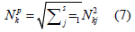
where Nkp is the resulting force of a certain type on the k-th cross-section under consideration, Nkj is the magnitude of the force of a certain type on the k-th cross-section, obtained for the j-th mode of oscillations. The magnitudes of structural displacements during seismic interaction are determined by the formula.
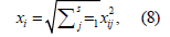
Where xi is the calculated value of the displacement of a structure point in the direction of the i-th generalized coordinate (i=1…N); xij is the i-th element of the vector {x}i , which is the displacement of a structure point in the direction of the i-th generalized coordinate with oscillations along the j-th eigenform.
Given that the considered condenser design is in a complex stress state, the assessment of its strength is based on the analysis of principal stresses according to the Mises-Genk limit state theory, also known as the distortion energy theory [4,14]. The three values of the principal stresses σ0 represent the roots of the cubic equation determined by the components of the stress vector.
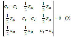
The principle stresses are denoted by σ1, σ2 and σ3 and are ordered in such a way that σ1 is the largest positive stress and σ3 is the largest negative one. In calculating the principal stresses σ1, σ2 and σ3, the equivalent von Mises stresses are given as

The equivalent stresses are related to equivalent strains by the following relation:

ν is Poisson’s ratio. The seismic resistance of a structure, when Normal Operation (NO) and Design-Basis Seismic (DBS) loads are combined, is verified by comparing the obtained total stresses with the corresponding allowable values according to [12]. In this study, the following NO and DBS loads were taken into account [12,15].
The NO loads are:
i. The weight of the condenser with water, in operational
condition, m=1659.5t.
ii. The atmospheric pressure acting on the condenser housing
from the outside.
iii. The pressure of the cooling water in the heat exchange pipes,
side and intermediate water chambers Pwtr=0.2MPa.
Considered as the DBS loads are the inertial seismic loads given by the response spectra in the directions x, y, z with the corresponding accelerations with the frequency ωj . To be able to simulate the dynamic effect, the bottom plate of the foundation is taken to be absolutely rigid. The calculated stiffness of the compensator between the LPC and condenser was: 5·107N/m along the turbine axis and 1·107N/m in the direction of steam supply from the LPC to the condenser through the adaptors (Figure 1). The boundary conditions that simulate the fastening of the condenser in the design three-dimensional model are: the rigid fastening of the entire row of supporting lower and side rods of the condenser in the foundation (Figure 1).
Figure 1: Three-dimensional model of the K-1000-60/1500 steam turbine condenser. Boundary conditions for fastening the condenser.

To calculate the K-1000-60/1500 steam turbine condenser design, only the Floor Response Spectrum (FRS) CA-482 taken from [12] was used, which was caused by the lack of seismic data at possible unit installation sites [4]. FRS CA-482 was obtained according to the results of processing the response spectra for a set of analog and synthesized accelerograms [12]. A detailed description of the FRS CA-482 used for the study has previously been presented in the paper [4]. The maximum level of DBS accelerations [12] is given below in (Table 1).
Table 1: The maximum level Of DBS accelerations.

Preparation of the FE Model
When creating the FE model of static and dynamic problems, a 10-node three-dimensional tetrahedral FE was used [4,16]. During the creation of the FE mesh, both hexahedral and tetrahedral elements were considered, however, due to the significant complexity of the condenser, as well as with the purpose of simplifying the dimensionality of the iterative calculation for modeling, the tetrahedral element was adopted [16]. This element allows us to specify boundary conditions depending on the type of kinematic connection, namely displacements, velocities, accelerations, etc. This is a three-dimensional quadratic element of the problems of mechanics of a deformable rigid body with ten nodes and three degrees of freedom in each node: displacements in the direction of the X, Y, and Z axes of the nodal coordinate system. The FE has a quadratic representation of displacements, and is able to use an irregular mesh shape, which is important when creating computational FE models on the basis of solid models imported from various system design software [16, 17]. When choosing the FE model, an analysis was performed to determine the optimal FE size. As a result of the analysis it was determined that the optimal FE size is 150mm. With a further decrease in the FE size, the accuracy of calculation changes insignificantly, with the number of elements growing rapidly. When the original model was broken, about 2.1 million FE and 4 million nodes were obtained.
Analysis of the Results Obtained
For the condenser, the eigenforms of oscillations were obtained, whose frequencies are given below in (Table 2). The analysis of the experimental studies of the seismic resistance of such structures [4,12,18] showed that in the field of seismic resonance is only the first natural frequency. In this paper, the calculation of the first five natural frequencies is performed. The purpose of the calculation is to find the lowest natural frequency of the structure, which has the largest amplitude of oscillations and is the most dangerous for the seismic resistance of the structure [4,12]. According to [17,19] and by analogy with the formula
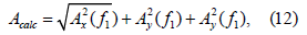
at the first natural frequency (Table 1), using the FRS CA-482 and the maximum level of DBS accelerations, we find the inertial seismic loads (accelerations), which equal to a=0.98m/s2 for the horizontal plane and are 67% of the horizontal component for the vertical one [4,12]. It should be noted that there are no seismic observations at the site and in the area of Yuzhnoukrainsk NPP; therefore, there are no instrumental data on specific earthquakes at Yuzhnoukrainsk NPP. The data of specific research studies confirm the dominance of Carpathian earthquakes in the region of Yuzhnoukrainsk NPP. Additional comprehensive seismic surveys of at the Yuzhnoukrainsk NPP site that were performed in the early 90s by the Ekotsentr of NTU “Krym” confirmed the magnitudes for design earthquakes making magnitude 5 [12,19-22] and for maximum design earthquakes making magnitude 6 approved for Yuzhnoukrainsk NPP design project. However, instrumental measurements showed that the maximum (peak) accelerations on the earth’s surface in the area of Unit 1 reach 0.1g for design earthquakes and 0.15g for maximum design earthquakes [5], which fully correlates with the found values of accelerations.
Table 2: Forms of condenser oscillations.

Without reference to these additional studies, Stevenson and Associates (Cleveland, Ohio, USA) carried out and published an analysis of the seismicity levels of NPP sites in Eastern Europe, according to which the value of the peak horizontal seismic acceleration for Yuzhnoukrainsk NPP is recom-mended to be not less than 0.15g [5]. The aforementioned fact additionally confirms the adequacy of the use of FRS CA-482 for the analysis of seismic resistance of equipment at Yuzhnoukrainsk NPP. The condenser housing is made of grade 20 carbon steel. Nominal admissible stresses are calculated according to the norms [20] by the formula:

where RTCALC0.2 = 216MPa is the minimum value of the yield strength at the design temperature Т=50 °C [19]; RTstr = 363MPa is the minimum value of the tensile strength at the design temperature Т=50 °C [19]; [σ]=140MPa is the nominal value of allowable stresses [19]; Combined NO and DBS loads (σs)= 1.9.[σ ] =265 MPa. For the convenience of analyzing the results of calculating the stress-strain state of the condenser support structure, the support rods are numbered (Figure 1). As a result of solving the problem of determining the stress-strain state when the NO and DBS loads are combined, the distribution of equivalent stresses in the condenser supports (Figure 2) is obtained. In addition to the maximum equivalent stresses, with the NO and DBS loads combined in the condenser supports, the stress-strain state during seismic interaction was also assessed from the displacements of the supports (Figure 3). As can be seen from the figure, for the considered load level, the displacement of the condenser supports in the direction of the turbine axis does not exceed 6mm.
Figure 2:The distribution graph for equivalent stresses in the condenser supports with the NO and DBS loads combined.

Figure 3: The distribution graph for displacements in the direction of the turbine axis in the condenser supports with the NO and DBS loads combined.

Conclusion
An algorithm for confirming the seismic resistance of equipment by a calculation method is proposed. A mathematical model of equipment is developed, and an example of determining the natural frequencies, stresses and displacements in a structure is given. In the course of work, the natural frequencies were determined, and the structural strength was calculated with the assessment of seismic resistance. The novelty and practical value of the presented work is that the given technique allows us not only to determine the features of the complex stress-strain state of the equipment that directly interacts with the foundation and carries the load during an earthquake, but also allows determining the boundary conditions for further analysis of the reliability of related equipment.
References
- Gontarovskiy PP, Garmash NG, Shulzhenko NG (2016) Methods of calculating the dynamics of the system "Turboaggregate-foundation-base" of power units under seismic impacts. Vestnik NTU KHPI. Series: Power and Heat Engineering Processes and Equipment 8(1180): 153-160.
- Shulzhenko MH, Hontarovskyi PP, Harmash NH, Hliadia AO, Shvetsov VL, et al. (2016) Estimation of reaction of the powerful turbine unit to seismic loading. Vibration in Engineering and Technology 2(82): 85-93.
- Králik J (2020) Probabilistic safety assessment to determine the seismic fragility of NPP. MATEC Web of Conferences 313: 1-8.
- Palkov SA, Palkov IA (2021) Calculated determination of the seismic resistance of nuclear power plant equipment. Journal of Mechanical Engineering 24(2): 24-36.
- Breslavsky DV, Chuprynin A (2021) Analysis of Creep, shrinkage and damage in armored concrete dome at static and seismic loading. Nonlinear Mechanics of Complex Structures 157: 265-277.
- International Atomic Energy Agency (2019) Management of project risks in de-commissioning. Safety Reports Series, Austria, pp. 1-57.
- International Atomic Energy Agency (2020) Establishing the safety infrastructure for a nuclear power programme. Safety Standards Series No. SSG-16, Austria, pp. 1-169.
- International Atomic Energy Agency (2021) Decontamination approaches during outage in nuclear power plants-Experiences and Lessons Learned. IAEA-TECDOC-1946, Austria, pp. 1-94.
- International Atomic Energy Agency (2021) Seismic instrumentation system and its use in post-earthquake decision making at nuclear power plants. IAEA-TECDOC-1956, Austria, pp. 1-246.
- Palkov I, Palkov M (2020) Stress strain state of steam turbine components under plastic deformation. Journal of Mechanical Engineering 4(88): 14-17.
- Rusakov AI (2020) Fundamentals of structural mechanics, dynamics and stability. 1st (edn.), CRC Press, USA, pp. 1-480.
- (1981) The equipment of nuclear power plants. Calculation of the strength of the seismic impact: RTM 108.020.37-81. NPO CKTI. Leningrad pp. 1-39.
- Szeidl G, Kiss L (2020) Mechanical vibrations: An introduction. USA, pp. 1-455.
- Ugural AC, Chung Y, Ugural EA (2020) Mechanical engineering design. 3rd (Edn.), CRC Press, USA, pp. 852.
- Emarah E, Kasban H (2021) Efficient evaluation of heat exchangers behaviour in nuclear power plants. Arab Journal of Nuclear Sciences and Applications 54(2): 126-136.
- Lee S, Chung P (2021) Finite element method for solids and structures: A concise approach. Cambridge University Press, UK, pp. 1-366.
- Palkov SA, Shulzhenko MH (2019) Elastic stress-strain state of elements of the internal high-pressure casing for steam turbines. Journal of mechanical engineering 22(4): 32-40.
- Králik J (2019) Experimental and numerical analysis of the seismic safety of technology support structures in NPP. AIP Conference Proceedings 2116(1).
- (1989) Rules of strength calculation for equipment and pipelines of nuclear power plants (PNAE G-7-002-86): Gosatomenergonadzor of the USSR. Energoatomizdat Publishers Russia, pp. 1-525.
- (1991) GOST 17516.1-90. Electric technical devices. General requirements for environment mechanical stability. Introduced 01.01.91, Standardinform, Russia, pp. 1-7.
- (2001) Standards for design of seismic resistant nuclear power plants: NP-031-01. Gosatomnadzor of Russia, Russia, pp. 1-50.
- (2020) IEEE/IEC International Standard-Nuclear facilities-Equipment important to safety-Seismic qualification. pp. 1-82.
Editor In Chief


.jpg)


Signup for Newsletter

Quick Links
 Editorial Board Registrations
 Submit your Article
 Refer a Friend
 Advertise With Us
Our Recent Edition

.jpg)


Top Editors


.jpg)


.bmp)
.jpg)
.png)
.jpg)


.png)

.png)


.png)


Financial Support

Sponsors

Latest e-Books

Latest Video

 a Creative Commons Attribution 4.0 International License. Based on a work at www.crimsonpublishers.com.
Best viewed in
a Creative Commons Attribution 4.0 International License. Based on a work at www.crimsonpublishers.com.
Best viewed in