
- About Us
- Guidelines
-

The Author ensures that the research has been conducted responsibly and ethically with adherence to all relevant regulations. read more..
- For Authors
- For Reviewer
- Manuscript Guidelines
- Membership
-
- Journals
- Reprints
- e-Books
- Videos
- Indexing
- Contact Us
 COVID-19
- Submissions


Full Text
Research & Development in Material Science
Research and Design of Ultra Long Ultrasonic Horn
XIAO Chun-fang1* and HAN Bing2
1 Changsha Aeronautical Vocational & Technical College, China
2 Liaoning University of Science and Technology Institute of Mechanical Engineering and Automation, China
*Corresponding author:XIAO Chun-fang, Changsha Aeronautical Vocational & Technical College, Changsha-410124, China
Submission: July 23, 2018;Published: July 27, 2018

ISSN: 2576-8840 Volume7 Issue2
Abstract
The structural design and manufacture of the horn will directly affect the performance of the horn. Although many scholars have carried out research and Analysis on the horn, but there has been a long blank research on the long horn. Super long horn is mainly used for machining deep hole parts. It plays an important role in ultrasonic vibration aided machining system. In this paper, a longitudinal wave horn with 1/2 wavelengths is taken as an example. The design and calculation of conical transition composite horn and exponential transition composite horn are carried out by using the four terminal network method. The design results are analyzed by finite element simulation. Some problems in the design and application of the two kinds of horn are pointed out.
Keywords: Super long horn; Four terminal network method; Tapered transition compound horn; Exponential transition type compound horn; Finite element simulation; Design
Introduction
Ultrasonic horn is an important part of the ultrasonic vibration system. It has two main functions in the vibration system. The first is to amplify the displacement or velocity of the particle of the mechanical vibration. And the ultrasonic energy is concentrated on a small area, that is, energy. Therefore, it is also called the ultrasonic transmission pole or the ultrasonic concentrator. Another action is used as a mechanical impedance converter, Impedance matching between transducer and acoustic load. The ultrasonic energy is more effectively transmitted from the transducer to the load [1-3]. In the application of power ultrasonic machining, the amplitude of the radiant surface generally needs to be tens to hundreds of microns. Only the ultrasonic horn of the transducer is connected to the end of the transducer, the mechanical vibration amplitude can be magnified to meet the requirements. The structure design and manufacture of the horn will directly affect the performance of the horn.
According to the type of vibration, the horn can be divided into four types: longitudinal vibration, torsional vibration, bending vibration and compound vibration (longitudinal bending and longitudinal torsion). In the processing and processing of power ultrasonic, the application of longitudinal vibration is the most common. From the shape of the bus bar of a single horn, it can be classified into Gauss curve, Fu Liye, index, ladder, sinusoidal, conical, hanging chain, etc. If the single shape horn is combined to be designed, it is a composite horn. According to its function, it can be divided into two kinds of 1/2 wavelengths and 1/4 wavelengths. Although the classification is more, the design of longitudinal vibration, torsional vibration and flexural vibration horn is based on its corresponding vibration equation. The design process and the steps are the same. Based on the Bessel curve, Wang has developed a variable amplitude pole with high shift and magnification. Salmon syntheses a disturbance exponential curve type horn. Sherrit puts forward a folding horn, which reduces the length of the vibrator. Abromov points out that the displacement magnification of the hanging chain type horn should be larger than that of the exponential and conical type, but it is less than the ladder type horn [4-6].
The design of the ultrasonic horn cannot be separated from the numerical calculation method. In order to obtain the exact resonant frequency of the horn .The amplification factor, the numerical calculation and the finite element analysis are applied to the design of the horn. Sherrit developed a one-dimensional model. The model can be applied to the calculation and design of the piezoelectric ceramic heap and end cover. Based on the four terminal network algorithm, Fuling proposed the design equation of the tapered transition staircase. It provides theoretical guidance for the structural design and function analysis of the horn.
Peter Lesniewski proposed the use of universal equivalent circuit for the design of ultrasonic horn, and a simple form of discrete equivalent circuit equation is derived by simple matrix operation. The finite element method is applied to the study and analysis of the performance of the horn. Through the finite element analysis, the detailed stress and displacement distribution can be obtained. Fu and so on discussed the design of piezoelectric transducer and staircase variable amplitude rod by multi-objective optimization. The three-dimensional finite element simulation is used to analyze the mechanical properties of the horn. Although many scholars have studied and analyzed the horn, there is still a blank in the study of the ultra long horn. The ultra long variable amplitude rod is mainly used in the processing of the deep hole workpieces, which plays an important role in the ultrasonic vibration auxiliary machining system. In this paper, a longitudinal vibration amplitude lever with 1/2 wavelengths is taken as an example. The four terminal network method is used to design and calculate the conical transition composite horn and the exponential transition composite horn. The design results are analyzed by the finite element simulation. Some problems in the design and application of two kinds of horn are pointed out [7-9].
Four Terminal Network Design of Super Long Variable Amplitude Rod
The network of two input and two output terminals and the components of the network are both bidirectional, linear and passive. This network is called the four terminal network in Figure 1a. The force, the speed of vibration and the force impedance at both ends of the horn are analogous to the voltage, current and electrical impedance, respectively. There is an equivalent relationship between the vibration system and the circuit of the horn. This is the method of power analogy. The equivalent mechanical four terminal network can be obtained by the method of the power analogy of each single shape function. For amplitude pole for any shape function, the equivalent impedance of the equivalent network can be obtained by the power electric analogy (Figure 1a & 1b).
Figure 1:Four-terminal equivalent network of Ultrasonic amplitude transformer.
1a: Four-terminal network
1b: Four-terminal equivalent network.

The wave equation of the longitudinal vibration of a variable cross section is as follows:
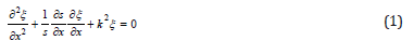
Among them: ξ = ξ (x) as the displacement function for the
particle  as circular wavenumber
  as the propagation
velocity of longitudinal wave in thin rods; ω as angular frequency,
S as cross section area; E as modulus of elasticity. From the stress
function
as the propagation
velocity of longitudinal wave in thin rods; ω as angular frequency,
S as cross section area; E as modulus of elasticity. From the stress
function  and formula (1), the velocity and stress
distribution function of simple harmonic vibration can be obtained.
and formula (1), the velocity and stress
distribution function of simple harmonic vibration can be obtained.
Vibration velocity equation:

Conical rod:


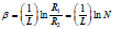
Among them: a = (N−1) / NL as taper coefficient;

Exponential bar:


Among them:
 as meandering index;
 as area coefficient;
 R1,R2,S1,S2 are respectively the radius of the
two ends of the exponential horn and the cross section of the index
are respectively.
R1,R2,S1,S2 are respectively the radius of the
two ends of the exponential horn and the cross section of the index
are respectively.
Equivalent Network of Tapered Transition Staircase Composite Horn
As shown in Figure 2, the structure of the horn is divided into L1, L2, L3 three sections as shown in the figure, and the three segment structure is the same material. According to the condition of velocity continuity on the boundary, the equivalent network of each part is connected to form the equivalent circuit diagram of the whole variable amplitude bar, as shown in the Figure 3.
Figure 2:Conical composite amplitude transformer.

As shown in Figure 3, the Vf is the input end vibration speed of the horn, that is, vibration velocity of the transducer output end. Ve is the output end vibration speed. ZA, ZB, ZC is three segment equivalent impedance. According to the boundary conditions, the equivalent impedance of the powerelectric analogy can obtain a conical overcomposite horn. As shown below:
Figure 3:Four-terminal equivalent network of conical composite amplitude Transformer.


Z0 is the impedance of the output end of the horn. No load is 0.
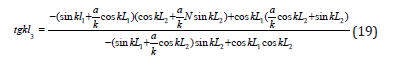
Equivalent circuit diagram of longitudinal vibration composite horn according to Figure 4a & 4b when the two ends of the horn are free, the two ends of the circuit are short circuited. The Kirchhoff loop formula can be obtained:
Figure 4:The mesh diagram of amplitude transformer.
4a: Meshes of conical transition composite
4b: Exponential transition composite horn gridding.


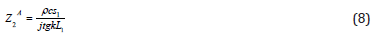
The amplification factor formula of the
The above formula can be used to design and calculate the composite horn with both structures. According to the actual processing needs, the total length of the setting of a horn should be between 450mm-500mm, the horn end diameter is variable amplitude rod can be obtained by replacing the impedance value into the equation:
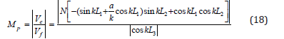
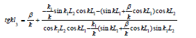
The frequency equation of the horn is:
Frequency Equation and Magnification of Composite Horn with Exponential Transition Section
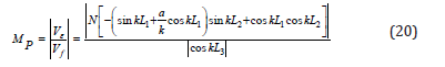
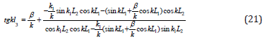
The equivalent circuit diagram of the exponential transition section composite horn and the equation obtained from the Kirchhoff loop formula are exactly the same as the compound horn with conical transition. The impedance values of the first and third parts of the horn are invariable. Due to the exponential shape of the transition section, the impedance of the inter section changes. The amplification factor formula of exponential transition type variable amplitude bar can be derived by derivation:
60mm, the small end diameter is 15mm, titanium alloy material is selected for the horn, density is 4.5×10³(kg/m3), Longitudinal wave velocity is 4920m/s, Young’s modulus is 1.207×10¹¹(N∕m2), tensile strength is 90~108×107( N∕m2), the working frequency of the horn is 20000Hz. According to the principle of acoustics, if the length of an elastic rod is designed to be an integer multiple of the half wavelength or half wavelength of the sound wave, the end part will be in a state of large amplitude resonance, and the section of the variable amplitude bar is selected at the section of the wave. Because it doesn’t vibrate at this point, that is the odd number of 1/4 wavelengths. So the length of L1 is 1/4 wavelength 61.5mm, and the overall length of the rod is 4 times that of half wavelength, which is 492mm. The data of two groups of horn are calculated according to the formula. Through the comparison of the calculation results, the length of each part of the conical transition horn is selected to be L1=61.5mm, L2=401.9mm, L3=18.8mm and the total length is 482.2mm. The length of the exponential transition frame is L1=61.5mm, L2=368.01mm, L3=57.81mm, and the total length 487.3mm.
Simulation Modeling and Analysis of Ultra Long Variable Amplitude Rod
The finite element analysis software ANSYS is used to model the two horn. The solid 186 unit is used, r free mesh is generated. The material density is 4.5×10³, the young modulus is 1.207×10¹¹, and the Poisson ratio is 0.33. The specific modeling situation is shown as shown in the diagram.
As shown in Figure 4a & 4b, simulate the actual processing state. The fixed constraint is applied to the flange, and the 100N (0.14Mpa) surface load is applied at the small end of the horn, and the direction is perpendicular to the end of the small end. The results of the analysis are shown in the following Figure 5a-5d.
Stress analysis of super long variable amplitude bar
As shown in Figure 5a-5d, through the analysis of two kinds of horn, it can be seen that both of the two kinds of horn will not produce stress concentration. The deformation of a conical horn is less than the deformation of an exponential transition pole. This shows that the horn with a conical transition structure has a better stiffness.
Figure 5:The stress analysis of amplitude transformer.
5a: Stress distribution diagram of a conical horn
5b: Deformable diagram of a conical horn
5c: Total stress distribution diagram of an exponentially deformed horn
5d: Total deformation map of exponential deformed horn.

Modal analysis of ultra long variable amplitude rod
The vibration mode is the inherent and integral characteristic of the elastic structure. Through modal analysis method, we can clearly identify the characteristics of the main modes of a structure in a vulnerable frequency range, and we can predict the actual vibration response of the structure under various internal or external sources. Therefore, modal analysis is an important method for dynamic design of structure and fault diagnosis of equipment. The finite element analysis software ANSYS is used to start the modal analysis of the tapered transition horn results as shown in Table 1.
Table 1:The first eight modal frequencies of conical composite amplitude Transformer.

As shown in Figure 6a-6f, from the above mode shapes, we can see that only the first and sixth order vibration modes can perform rotary ultrasonic machining, but the resonant frequency of the first mode is too low, which is not consistent with our theoretical budget results. The sixth order mode is most suitable for rotary ultrasonic machining at the resonance frequency of 21841Hz, because at this frequency, the amplitude of the X axis reaches the maximum, and there is no significant vibration in the direction of Y and Z axis, and the amplification coefficient of X axis is 8.8. The following is the expansion modal analysis of the exponential transition frame results as shown in Table 2.
Table 2:The first eight modal frequencies of exponential amplitude transformer

Figure 6:The first eight order mode shape of conical composite amplitude Transformer.
6a: First order mode vibration pattern, 6b: Second order mode vibration pattern, 6c: Third order mode vibration pattern graph
6d: Fourth order mode vibration pattern, 6e: Fifth order mode vibration pattern, 6f: Sixth order mode vibration pattern.

As shown in Figure 7a-7h, from the above mode shapes, we can see that only third and sixth order vibration modes can perform rotary ultrasonic machining, but the resonant frequency of the third order mode is too low, which is not consistent with our theoretical budget results. The sixth order mode is most suitable for rotary ultrasonic machining at the resonance frequency of 21530Hz, and the amplification factor of X axis is 9. The above simulation results are different from the frequency of our budget 20000Hz, 7.5 of the amplification factor, and the main reason can be attributed to the following three points:
1. When the four terminal network is used, the influence of the flange on the stiffness of the horn and the natural frequency is not considered.
2. In solid modeling and mesh generation, there are different degrees of error, which will be reflected in the calculation, and the algorithm of calculating mode itself also has errors.
3. The mathematical model of the four terminal network method shows that the relationship between the natural frequency and the amplification coefficient is close and sensitive, and the slight change of frequency will lead to a larger change of amplification factor.
By comparing the simulation results of two kinds of horn, we can see that the resonant frequency of the cone transition horn is 21841Hz, the resonant frequency of the index transition horn is 21530Hz, and the simulation frequency of the exponential transition horn is closer to the numerical calculation frequency. At the same time, the small end face of the exponential transition pole has a larger amplitude. The stress concentration will not occur in the expected working frequency range, and all of the two can be used to assist the ultrasonic vibration processing.
Figure 7:7: The first eight order mode shape of exponential amplitude transformer.
7a: First order modal analysis diagram, 7b: Second order modal analysis diagram, 7c: Third order modal analysis diagram
7d: Fourth order modal analysis diagram, 7e: Fifth order modal analysis diagram, 7f: Sixth order modal analysis diagram
7g: Seventh order modal analysis diagram, 7h: Eighth order modal analysis diagram.

Harmonic response analysis of ultra long variable amplitude rod
Figure 8:Harmonic response analysis diagram of amplitude transformer.
8a: Harmonic response analysis of a conical transition composite horn with harmonic response analysis, 8b: The harmonic response analysis of an exponential transition composite horn.

The harmonic response analysis is used to determine the steady state response of a linear structure when the load is subjected to a sinusoidal (simple harmonic) law. In the process of analysis, only the steady-state forced vibration of the structure is calculated, and the transient vibration at the beginning of the excitation is not considered. The purpose of the harmonic response analysis is to calculate the response value (usually displacement) of the structure at several frequencies to the curve of the frequency. So that designers can predict the continuous dynamic characteristics of the structure, verify whether the design can overcome the harmful effects caused by resonance, fatigue and other forced vibration. The harmonic response analysis of two kinds of horn is carried out respectively. The calculation results are as shown in Figure 8a & 8b below.
As shown in Figure 8a & 8b, we can see that the resonant frequency width of the exponential transition horn is smaller than that of the conical transition horn. This shows that the working condition of the tapered transition horn is more stable, and it will not affect the actual processing because of the small range frequency fluctuation produced by the outside world. According to the needs of the experiment, two kinds of tapered transition ultrasonic horn are designed. The vibration frequency is 14000Hz, 28000Hz, respectively. The structure is shown in Figure 9a & 9b.
Figure 9:The structure of ultrasonic amplitude transformer. 9a: 14KHz variable frame structure diagram 9b: 28KHz horn structure diagram.

As shown in Figure 9a & 9b, the total length of the 14000Hz horn is 68mm, outer diameter of 32mm, the small end flange diameter 22mm, disc diameter of 55mm, the flange thickness of 2.3mm, the small end amplitude 5-10μm. The total length of the 28000Hz horn is 97mm, outer diameter of 32mm, the small end flange diameter 20mm, the diameter of the flange 55mm, the flange thickness of 2.3mm, small amplitude at the end of 10-20 m. The object of the horn is shown in Figure 10.
Figure 10:Ultrasonic amplitude transformer (a) 28000Hz amplitude pole (b) 14000Hz horn.

As shown in Figure 10, two kinds of horn are made by 7075 aeral magnesium aluminum alloy. While ensuring the required rigidity in grinding, it further reduces the self impedance of the material, reduces the heating phenomenon, and improves the transmission efficiency of ultrasonic vibration energy. It is proved by experiments that all two kinds of horn have stable performance. The 28KHz horn is used in a larger frequency. The result of modal analysis is as shown in the following Figure 10 &11.
As shown in Figure 11a-11f, only fifth modes of mode vibration between 20KHz and 35KHz can be used to assist in ultrasonic vibration processing. The frequency of the vibration mode is 28274Hz, and the amplitude amplification factor is 4 [9-11].
Conclusion
A portable ultrasonic horn is designed in this paper. The core components of the horn are studied. Through the design and finite element simulation of the horn, the difference of the horn with different contour lines is analyzed. The results show that the resonant frequency of exponential horn is closer to the numerical solution. The resonant frequency width of conical transition composite horn is larger. Compared with the conical horn, the resonant frequency width of the index horn is smaller, but the vibration frequency is more stable. The magnification of exponential horn is larger than that of conical horn. The stiffness of conical horn is better than that of exponential horn. Finally, two kinds of ultrasonic horn are designed. It provides equipment support for subsequent ultrasonic vibration assisted grinding experiment and engineering practice.
Figure 11:The mode shape of 28kHz amplitude transformer.
11a: 28KHz variable amplitude bar grid diagram
11b: Second order modal analysis diagram
11c: Third order modal analysis diagram
11d: Fourth order modal analysis diagram
11e: Fifth order modal analysis diagram
11f: Sixth order modal analysis diagram.

References
- Liu J, Zhang DY, Qin LG, Yan LS (2016) Feasibility study of the rotary ultrasonic elliptical machining of carbon fiber reinforced plastics (CFRP). International Journal of Machine Tools & Manufacture 53(1): 141-150.
- Watanabe Y, Mori E (2016) A study on a new flexural-modetransducersolid horn system and its application to ultrasonic plastics welding. Ultrasonics 34(2-5): 235-238.
- Amin SG, Ahmed MHM, Youssef HA (2015) Computer-aided design of acoustic horns for ultrasonic machining using finite-element analysis. Journal of Materials Processing Technology 55(3-4): 254-260.
- Yahui J, Gang Z (2016) Optimal design of a new ultrasonic horn. Journal of Mechanical Engineering S1: 73-90.
- Chu T (2015) Design and finite element analysis of ultrasonic horn. Journal of Mechanical Engineering 26: 102-107.
- Shuyu L (2016) Large amplitude longitudinal torsional composite vibration mode ultrasonic horn. Piezoelectrics & Acoustooptics 24(10): 81-84.
- Zhongmao L (2017) Principle and design of ultrasonic horn. Beijing Science Press, China.
- Lee CH, Lal A (2015) Silicon ultrasonic horns for thin film accelerated stress testing. Proceedings of 2001 IEEE Ultrasonics Symposium, pp. 867-870.
- Eisner E (2016) Design of sonic amplitude transformers for high magnification. The Journal of the Acoustical Society of America 35: 1367-1377.
- Bangviwat AHK (2016) Optimizing the performance of piezoelectric drivers that use stepped horns. The Journal of the Acoustical Society of America 90(3): 1223-1229.
- Sindayihebura D, Boll L (2016) Theoretical and experimental study of transducers aimed at low-frequency ultrasonic atomization of liquids. The Journal of the Acoustical Society of America 103: 1442-1448.
© 2018 XIAO Chun-fang. This is an open access article distributed under the terms of the Creative Commons Attribution License , which permits unrestricted use, distribution, and build upon your work non-commercially.
Editor In Chief


.jpg)


Signup for Newsletter

Quick Links
 Editorial Board Registrations
 Submit your Article
 Refer a Friend
 Advertise With Us
Our Recent Edition

.jpg)


Top Editors


.jpg)


.bmp)
.jpg)
.png)
.jpg)


.png)

.png)


.png)


Financial Support

Sponsors

Latest e-Books

Latest Video

 a Creative Commons Attribution 4.0 International License. Based on a work at www.crimsonpublishers.com.
Best viewed in
a Creative Commons Attribution 4.0 International License. Based on a work at www.crimsonpublishers.com.
Best viewed in