- Submissions

Full Text
Research & Development in Material Science
Micro Structural Features Induced by Sheet Hydroforming of Non- Ferrous Metals and Alloys
Forouhandeh F1*, Kumar S2 and Ojha SN3
1Department of Engineering, Shahrood Branch, Islamic Azad University, Shahrood, Iran
2Department of Mechanical Engineering, Indian Institute of Technology (BHU), India
3Department of Metallurgical Engineering, Indian Institute of Technology (BHU), India
*Corresponding author:
F Forouhandeh1*
Department of Engineering, Shahrood Branch Islamic Azad University, Shahrood, Iran
S Kumar2
Department of Mechanical Engineering, Shahrood Branch IIT (BHU), Varanasi, India, 221005
SN Ojha3
Department of Metallurgical Engineering, IIT (BHU), Varanasi, India, 221005
Submission: August 21, 2017; Published: September 22, 2017

ISSN : 2576-8840Volume1 Issue2
Abstract
Sheet hydroforming process has been used for near-net shape forming of non-ferrous metals and alloys. A commercial purity Al, Cu and Ti metals as well as α-brass an alloy of Cu-Zn has been formed into various shapes using an indigenously designed experimental set-up. The process parameters have been selected based on the previous study on simulation of this process. The process is shown to exhibit a better surface quality of products together with relatively high drawing ratio. These effects along with uniform distribution of stresses cause considerable reduction in secondary processing of the component. The micro structural features of sheet hydro-formed products are reported. The uniformity in grain size and grain size distribution of all the materials employed in the present work are presented and discussed. Important advantages of this method vis-à-vis conventional cup drawing techniques are illustrated.
Keywords: Sheet hydroforming; Tube hydroforming; Non-ferrous metals; CP titanium; Optical metallography
Introduction
Hydroforming is a popular forming process today to meet the challenges of various industries. Tube hydroforming [THF] and sheet hydroforming [SHF] are relatively complex manufacturing processes.
SHF process is better than the conventional manufacturing done via stamping and welding such as:a. Part consolidation resulting in weight reduction of the component
b. Weight reduction through more efficient section design and tailoring of the wall thickness
c. Reduced tooling cost
d. Improved structural strength and stiffness
e. Less number of secondary operations
f. Reduced dimensional variation
g. Significant reduction in spring back effects and
h. Reduced scrap rate [1]
The analysis and performance of the process depends on many factors such as part geometry and design, material and process parameters and the boundary condition of forming.
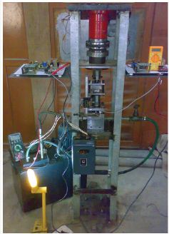
The best and easiest way to study the behavior of the process for these alloys is by Finite Element Method and Computer aided engineering based procedure. The technology of product manufacturing by THF and SHF is developing very fast to shape complex profiles of sheet products. Although a lot of research works has been reported about sheet/tube hydroforming, still Lack of research works regarding microstructure analysis of hydroformed products of light alloys especially Titanium is obvious [1-8]. An over view on hydroforming especially sheet hydroforming has been presented by authors [2]. An investigation regarding metallurgical and microstructural characterization of a hydroformed steel part has been already presented and Microstructural characterization by light optical metallography (LOM) and transmission electron microscopy (TEM), (including grain structures) was carried out [9]. There are some challenges such as optimization of process parameters related to SHF of CP Titanium and Titanium alloys and its experimental study. Microstructure analysis of hydro-formed parts is an area which is still to be exploited in the field of sheet hydroforming process. Better surface quality, reduced dimensional variation and smooth strain are some of the benefits of SHF in comparison to conventional method like deep drawing. Titanium due to HCP crystal structure and some special properties like high strength to weight ratio and ability to work in high temperature condition etc has become unique and applicable in aero space industries. Other metals and alloys like Al, Cu and brasses tolerate some operations due to their FCC structure and resulting high uniform elongation compared to Ti metal. Although sheet metal forming of Titanium is very difficult due to high spring back, strength against deformation in room temperature and low ductility but in case of appropriate deformation, products will be very strong and applicable in light structures. A sheet hydroforming setup has been designed and fabricated by authors as shown in Figure 1. Defect free products of different metals and alloys specially Titanium products has been presented.
Figure 1: Developed SHF setup [1].
The light metals and alloys generally require precise shape and good surface finish by virtue of their applications in automotive and aerospace industries. These qualities of a formed component have led to the development of a number of metal forming techniques. However, the materials properties and their deformation behavior are equally important in these forming processes. The resultant microstructure of the finished product provides a valuable insight into forming processes. A systematic investigation of these aspects of hydroforming process has not been reported. The objective of the present work is to investigate this aspect of the metal forming processes.
Experimental Details and Process Analysis
Process description and forming technique
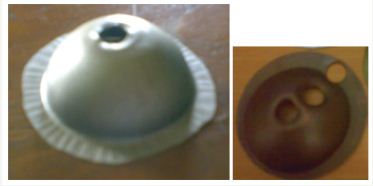
In this work hydro mechanical cup drawing (one category of sheet hydroforming process) has been used. Sheet/blank is restricted between die and blank holder. Punch will come down from up side and there is backward fluid pressure from the container. Therefore, fluid will push sheet towards punch. Precision of punch geometry (especially any angle) is so considerable [1,10]. A typical shape of hydro-formed Titanium products has been shown in Figure 2. Products have semi spherical shape with 50mm diameter. Products obtained out of the setup have been cut using a punch (with 10mm diameter of cutting head) and a casted anvil as shown in Figure 3a.
Figure 2: Titanium products.
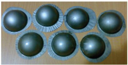
Figure 3: Detailed of arrangement for cutting the sample for metallographic
a. Casting anvil.
b. Cutting punch support.
c. Cutting punch.
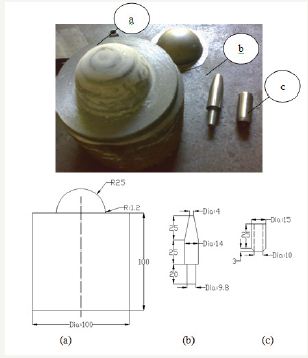
Material of block (a) is Cast iron and material of the cutting punch is hardened die steel. For any hydroformed product, three circular samples are cut. The aim of cutting the edges is to prevent any distortion in centre of sample using tooling as shown in Figure 3b & 3c.
Figure 4a shows different sheets after cutting the samples for getting the initial microstructure. The aim is to study the change of microstructure at three locations across a radius as shown in Figure 4b. Numbers 1, 2 and 3 are marked locations areas as under blank holder, middle region and the area where maximum deformation (peak of dome) occurs at the top of the dome (Figure 5a). Figure 5b shows samples of Copper obtained from three different areas. For any sample 2 or 3 small circular samples are cut for microstructural investigation.
Figure 4: a. Sheet/blank of different materials with sample for getting initial microstructure.
b. Hydroformed product of Copper.
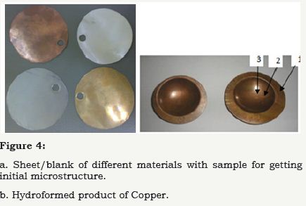
Figure 5: a. Sample in maximum deformation zone, material: CP Titanium grade 1.
b. Sample in three areas, material: Copper.
Microstructural examination
The samples for microstructural examination were cut from three different locations of the cup-shaped product. These were taken from the top, side and base region of the product. These samples were mounted in quick setting acrylic powders. Polishing has been carried using velvet cloth with Brasso. Kerosene has been used while polishing on cloth. The last operation has been done for about 10 times for Copper and Brass samples and about 27 times for Aluminum so as to remove all scratches. Ferric chloride consisting of 10 gram ferric chloride, 30ml hydro fluoric acid, 100ml water has been used as etchant for Copper and Brass samples and Kehler’s reagent having 3ml HCl, 5ml HNO3, 2ml HF, 190ml water is used for Aluminum samples. Also 50% Alumina and 50% water has been used during cloth polishing for Titanium sample and 5% HNO3, 10% HF, 85% water has been used as etchant for Titanium samples [1]. In this way a standard metallographic procedure has been used in the sample preparation. Image analyzer microscope (brand: ZEISS) with 1000x magnification has been used to get microstructure images. Microstructural examinations have been carried out in a Leitz optical metallograph attached to an Image Analyzer. Four different samples of Aluminum, Copper, Brass and Titanium have been taken to study the microstructural features of the formed samples. Measurement of grain size and comparison before and after deformation has been carried out following the Linear Intercept Method in different regions of the samples [11]. Accordingly,
d= (L (average). grain shape factor)/M
where d: grain diameter,
M: magnification and grain shape factor is constant for any material therefore for comparing before and after deformation can be neglected.
L(ave) = 1/N Σ L/ni
Where N: number of data, L: Real visible and measured test length and 〖n〗i Number of intercept. For all images, real magnification has been calculated from ratio of visible or actual standard length over written length. All the samples are of semi spherical sheet hydroforming products. These cups have been produced under hydro mechanical cup drawing process using developed SHF setup. Index 1, 2 and 3 are marked areas without deformation (under blank holder), middle region and the maximum deformation (peak of the dome) respectively. The main aim of this study is comparison between the microstructure distribution of area under blank holding (index 1) and area under maximum dome height (index 3) also finding an advantage of hydroforming method in comparison to conventional one. The same procedure is used for 10 small samples (10mm diameter) of four different materials. Thicknesses of samples are 0.41mm for Aluminum, 0.29mm for Copper, 0.35mm for Brass and 0.3mm for Titanium respectively. The samples were examined in an optical metallographic. It is also observed that location 1 corresponds to flange region and location 2 corresponds to middle region and location 3 corresponds to central region as shown in Figure 4b as well.
Figure 6: a. Brass 1.
b. Brass 2.
c. Brass 3.
d. Brass in initial condition.
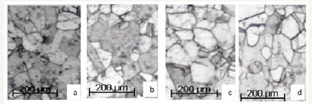
The microstructural features of brass samples taken from three different regions are shown in Figure 6a-6d. The above observations clearly show that microstructure and grain size of initial condition without deformation and index like cut samples in Figure 4a under blank holder (index 1) are very similar to each other. It can be said it happens because there is no considerable change in thickness in those two areas of the brass sheet. Microstructure images of all the samples show no appreciable change of grain size during cold deformation. Grain diameter of Brass 1a (under blank holder) and in initial condition are around 40μm while it is an average of 42μm for Brass-3 of the maximum dome height. In contrast, it is found to be 33μm for Copper-1 and 35μm for Copper-3. The same is around 16μm for Aluminum-1 and 17.5μm for Aluminum-3. The microstructure of copper samples is shown in Figure 7a-7d. The grain size of copper appears to be smaller than that of brass. There is some evidence of twinning in few grains. This reflects that copper samples are in annealed state prior to deformation. The uniformity in the grain size distributions appears to be better than that of the brass samples. In this case as well there is very small change in grain size before and after the deformation while there is change in shape of grain as elongated after the deformation as shown in Figure 7a- 7d. To find any change in the microstructure at different locations of any sample at the maximum deformation, three different regions have been focused as index 3-1, 3-2 and 3-3 in different materials. It is observed that deformation under sheet hydroforming is very smooth and strain in different places is distributed uniformly due to the similarity of microstructure. The microstructure of hydroformed Al is shown in Figure 8a-8d. The grain size appears to be uniform and relatively finer than that of Cu and brass samples. Some of the regions of the brass sheet revealed abnormal growth of the grains. These features are considered to have arisen from the base metals selected for hydroforming.
Figure 7: a. Copper 1.
b. Copper 2.
c. Copper 3.
d. Copper in initial condition.
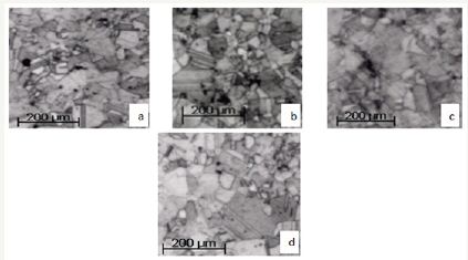
Figure 8: a. Aluminum 1.
b. Aluminum 2.
c. Aluminum 3.
d. Aluminum in initial condition.

Figure 9: a. Copper 3-1.
b. Copper 3-2.
c. Copper 3-3.

One of the main advantages of hydroforming process is better surface quality and constant deformation. The comparison of strain in different regions of a sample after deformation is compared w.r.t the microstructure as shown in the above micrographs. It appears that Aluminum sample has some impurity reflected in gray and dark areas as shown in Figure 8a-8d. Figure 9a-9c shows three different points of microstructure in the maximum deformation area for Cupper under sheet hydroforming process. It appears that this method has very uniform products.
Figure 10: Conventional cup drawing of
a. Copper 3-1.
b. Copper 3-2.
c. Copper 3-3.
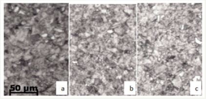
Figure 11: Microstructure of CP Titanium grade 1
a. Ti 1.
b. Ti 2.
c. Ti 3.
d. Ti in initial condition.

A test was carried by conventional cup drawing process on Copper using the same thickness and the amount of deformation. Sheet hydroforming has more uniform deformation in comparison to conventional cup drawing. In conventional forming processes, the strain is non-uniform throughout the circular sample (index 3, maximum deformation) of the component leading to nonhomogeneous grain size redistribution as shown in Figure 10a-10c. On the other hand, the strain is more uniform in the circular sample of the component in hydroforming process Figure 9a-9c. Consequently, there is considerable micro structural uniformity. This comparison has been done at the same location of the sample (index 3) under both kinds of metal forming. This micro structural analysis illustrates that deformation under soft punch in a sheet hydroforming process is more uniform as compared to that under hard punch used in a conventional cup drawing. Grain diameter of the CP Titanium sample before deformation is around 5μm (Figure 11a) and around 6μm after deformation (Figure 11b). Grain diameter in the area under blank holder Figure 11c (index-1) and initial condition as shown in Figure 11d are very similar. On one hand, the grain size has not been changed significantly but the grain shape has changed from equiaxed grain to elongated one. Deformation and strain has been very smooth which is reflected by uniform distribution of microstructure.
Table 1: A comparison between the result of microstructure of hydrofored cup and conventional processing one of Copper.

Table 1 shows a comparison between the result of microstructure of hydro formed cup and conventional processing one of Copper. All the microstructure images of initial conditions and under blank holder of any material are very similar to each other. Also there is no considerable change between images and grain size of middle section in comparison to under blank holder. But there are visual changes in grain shape between maximum dome height and others due to considerable deformation. Also there is considerable difference between the microstructure of hydro formed copper in comparison to conventional cup formed one in all the areas.
Conclusion
In this paper, material characterization for sheet hydro formed products has been presented. Four different metals and alloys have been used for investigation of microstructure analysis under sheet hydroforming process. Microstructure of any sample before and after deformation has been analyzed. An advantage of sheet hydroforming in comparison to conventional cup drawing due to uniform deformation has been illustrated.
References
- Forouhandeh F (2013) Development of a sheet hydroforming process for metals and alloys, PhD thesis, Department of Mechanical Engineering, Indian Institute of Technology (Banaras Hindu University), Varanasi, India, pp. 175-188.
- Forouhandeh F, Kumar S, Ojha SN, Balasubramanian R (2015) Recent development in micro hydroforming. Advances in Mechanical Engineering 5: 1-14.
- Zhang SH (1999) Developments in hydroforming. Journal of Materials Processing Technology 91(1-3): 236-244.
- Hein P, Vollertsen F (1999) Hydroforming of sheet metal pairs. Journal of Materials Processing Technology 87(1-3): 154-164.
- Novotny S, Hein P (2001) Hydroforming of sheet metal pairs from aluminium alloys. Journal of Materials Processing Technology 115(1): 65-69.
- Zhang SH, Zhou LX, Wang ZT, Xu Y (2003) Technology of Sheet hydroformings with a movable female die. International Journal of Machine Tools and Manufacture 43(2003): 781-785.
- Zampaloni M, Abedrabbo N, Pourboghrat F (2003) Experimental and numerical study of stamp hydroforming of sheet metals. International Journal of Mechanical Sciences 45(11): 1815-1848.
- Zhang SH, Wang ZR, Xu Y, Wang ZT, Zhou LX (2004) Recent developments in sheet hydroforming technology. Journal of Materials Processing Technology 151(1-3): 237-241.
- Murr LE, Gayton SM, Lopez MI, Bujanda DE, Whitmyre G, et al. (2008) Metallurgical characterization of a hydroformed, 304 stainless steel, Caribbean-style musical pan. J Mat Characterization 59(3): 321-328.
- Hosseinzadeh M, Mostajeran H, Bakhshi Jooybari M, Gorji A, Norouzi S, et al. (2009) Novel combined standard hydromechanical sheet hydroforming process. IMechE 6 Journal of Engineering Manufacture 224(3): 447-457.
- Underwood EE (1970) Quantitative stereology, Addison-Wesley Publishing Co, USA, pp. 37-47.
© 2017 Forouhandeh F, et al. This is an open access article distributed under the terms of the Creative Commons Attribution License , which permits unrestricted use, distribution, and build upon your work non-commercially.
 a Creative Commons Attribution 4.0 International License. Based on a work at www.crimsonpublishers.com.
Best viewed in


.jpg)


 Editorial Board Registrations
 Submit your Article
 Refer a Friend
 Advertise With Us
.jpg)


.jpg)


.bmp)
.jpg)
.png)
.jpg)


.png)

.png)


.png)


